Generator faults are usually serious and can lead to significant repair costs and long outage times.
PART I: ANALYSIS
Part 1 demonstrates how to analyze a stator ground fault for a large combustion turbine generator. The faulted phase and fault location are determined using fault voltage recorded by the numerical generator protection relay installed for this generator. This information is useful to determine whether any significant damage occurred and to quickly put the generator back in-service.
GENERATOR DATA
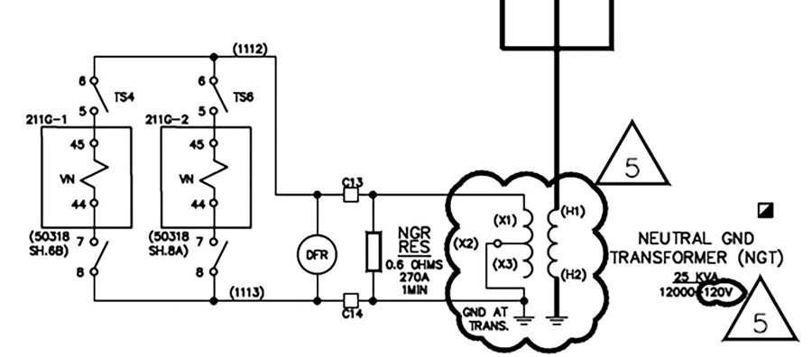
The generator is rated 13.8 kV line-to-line. The phase VT ratio is 120, and the grounding transformer turns ratio is 100. Figure 1 illustrates the connections for the grounding transformer. The generator is high-impedance grounded through a neutral resistor across the secondary of the grounding transformer to limit the magnitude of fault current flowing in the stator windings during a single phase-to-ground fault.

Figure 1: Grounding Transformer Connections
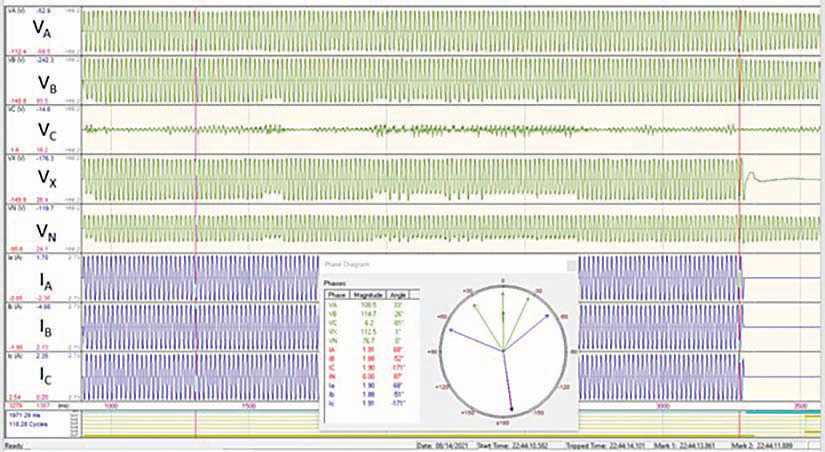
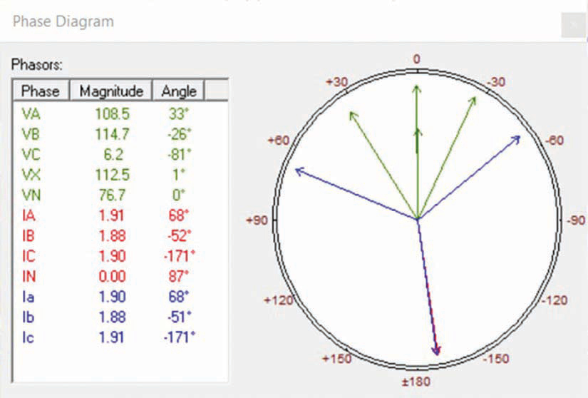
Figure 2A and Figure 2B show the oscillography and phasors corresponding to the fault signals recorded by the numerical generator protection relay during the event.

Figure 2A: Oscillography

Figure 2B: Phasors
Visual inspection of the oscillography clearly shows that the stator ground fault was located on phase C.
CALCULATING FAULT LOCATION
Determine the location of the stator ground fault (Figure 3) as follows:
- Generator terminal voltage = 13.8 kV/√3 = 7.97 kV line-to-ground (primary)
- Voltage across grounding transformer (VG) = (7.97 kV)/100 = 79.67 V (secondary)
- Neutral voltage (VN) = 77 V (secondary) taken from oscillography (voltage drop across neutral resistor)
- Fault location with respect to generator neutral: (VN*100%)/VG = 96.64%

Figure 3: Fault Location with Respect to Generator Neutral
The actual fault location was close to the generator terminals and just external to the stator windings. There is some error in the calculated fault location due to relay accuracy and resistive losses in the grounding transformer. This calculation provided confidence that the stator ground was not internal to the stator winding and the generator could quickly be returned to service.
PART II: ENHANCEMENT
Part II demonstrates how to enhance the performance of stator ground fault protection, including sensitivity and faster operating time. Note that it is always assumed the generator is high-impedance grounded through a neutral resistor across the secondary of a grounding transformer.
REACH OF 59N NEUTRAL OVERVOLTAGE PROTECTION
The neutral overvoltage function (59N) provides stator ground fault protection for high impedance grounded generators. The 59N function should provide ground fault protection for 90–95% of the stator winding (measured from the generator terminals). Note that the 59N function responds only to the fundamental frequency component.
Check the reach of the most sensitive element (59N1), which was originally set at 10.8 V secondary.

where:
P59N1 = 59N1 Voltage Pickup (10.8 V secondary)
VG = 79.67 V secondary (from fault location calculation)
Therefore, the original reach only covers up to 86% of the stator winding, which is less than recommended. Lowering the 59N1 voltage pickup to 5 V secondary (minimum setting) increases the reach to 94% of the stator winding, which is well within the recommended range. Now only the last six percent of the stator winding is unprotected.
ACCELERATING 59N NEUTRAL OVERVOLTAGE PROTECTION
This scheme provides fast tripping for ground faults in the generator zone without the typical long delay required to coordinate with transmission system ground fault relaying or VT fuses. Traditionally, 59N is delayed to properly coordinate with transmission system protection since significant voltage is developed at the generator neutral during ground faults in the adjacent transmission system. This is due to capacitive coupling across the GSU windings as illustrated in Figure 4.

Figure 4: Capacitive Coupling across GSU
The 59N accelerated tripping scheme uses sequence component supervision. This technique takes advantage of the fact that ground faults outside of the unit-connected generator produce some level of negative-sequence voltage on the low side of the GSU.
Therefore, detection of negative-sequence voltage (V2) indicates the ground fault is external to the unit-connected generator. If negative-sequence voltage is not detected, then tripping is accelerated since this indicates the ground fault is within the generator zone of protection.
The absence of negative-sequence voltage (a typical negative-sequence voltage inhibit setting is 5% of the positive-sequence voltage), and the presence of zero-sequence (V0) voltage (a typical zero-sequence voltage inhibit setting is 7% of the positive-sequence voltage) along with the pickup of the most sensitive 59N element (typical pickup setting is 5% of the generator nominal voltage) indicates a ground fault in the generator zone of protection.

Figure 5: Accelerated 59N Tripping Logic
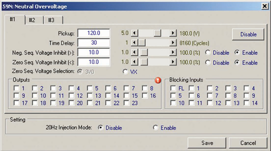
Figure 5 illustrates the logic for an accelerated tripping scheme. 59N1P is used along with both a negative-sequence voltage inhibit and zero-sequence voltage inhibit. Note that the accelerated tripping scheme (Figure 6) does not misoperate if the VT secondary is faulted since the negative-sequence voltage is significant for this condition.

Figure 6: Typical Accelerated 59N Tripping Scheme Setpoints
If the measured negative-sequence voltage is above the corresponding setpoint or the zero-sequence voltage is below the corresponding setpoint, then 59N2 uses a normal (longer) time delay.
OPEN BREAKER ACCELERATED GROUND FAULT PROTECTION
There is no need to coordinate for faults on the high side of the GSU when the low-side generator breaker is open. Therefore, a trip can be issued very quickly to the generator lockout relay if the pickup setting on 59N1 is exceeded when the low-side generator breaker is open (Figure 7).

Figure 7: Open Breaker Accelerated Tripping Logic
This scheme uses a three-cycle time delay on pickup. Note that this scheme does not coordinate with the VT fuses and is not required except for the VT secondary fuse on the neutral cable. Also note that even if mis-coordination with the VT fuses does exist, this may be acceptable because with the low-side generator breaker open, it is not a concern to trip for a VT fault or a VT secondary fault. Security is provided by blocking tripping when the low-side generator breaker is closed.
INTERMITTENT ARCING ACCELERATED GROUND FAULT PROTECTION
An integrated stall timer that incorporates memory of recent previous arcing events provides faster tripping for intermittent arcing.
Timer memory is accomplished by stalling timing of the pickup timer when the initiating function pickup intermittently drops out, as is the case for arcing faults.
The logic can be initiated by any ground fault protection function that is being used (e.g., 59N, 27TN, 59D, 64S). The integrated stall timer consists of both the pickup and reset timers. For this application, a pickup time of 10 cycles is used with a reset time of 300 cycles. For example, if there is an arcing fault with an accumulated 10 cycles worth of arcing with the time between arcs less than 5 seconds (Figure 8), then this scheme will trip:

Figure 8: Intermittent Arcing Accelerated Tripping Logic
The logic NOT 46DT AND NOT 52b is ANDed with the ground pickups to improve the security of this intermittent arcing protection by ensuring it does not falsely assert due to a phase-to-ground fault on the high side of the GSU. 46DT is a definite time negative-sequence overcurrent element.
CONCLUSION
Part I of this article demonstrated how to analyze a stator ground fault for a large combustion turbine generator. The faulted phase and fault location are determined using fault voltage recorded by the numerical generator protection relay installed for this generator. This information is useful to determine if any significant damage occurred and to quickly put the generator back into service.
Part II demonstrated how to enhance the performance of stator ground fault protection, including sensitivity and faster operating time.
 Steve Turner is in charge of system protection for the Fossil Generation Department at Arizona Public Service Company in Phoenix. Steve worked as a consultant for two years, and held positions at Beckwith Electric Company, GEC Alstom, SEL, and Duke Energy, where he developed the first patent for double-ended fault location on overhead high-voltage transmission lines and was in charge of maintenance standards in the transmission department for protective relaying. Steve has BSEE and MSEE degrees from Virginia Tech University. Steve is an IEEE Senior Member and a member of the IEEE PSRC, and has presented at numerous conferences.
