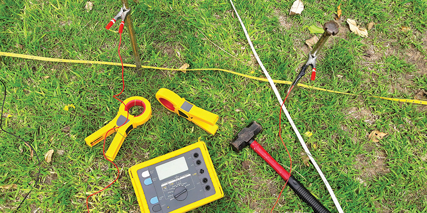
Ground testing is often thought of as ground electrode testing: the measurement of the resistance associated with a particular rod or grounding system. A useful corollary to this is soil resistivity testing. Resistivity is the electrical property of soil itself that determines how well it can carry current. It varies enormously (Table 1) depending on physical and chemical composition, moisture, temperature, and other variables. Measuring it is of paramount importance in designing a grounding electrode that will meet all the required electrical parameters for performance and safety.
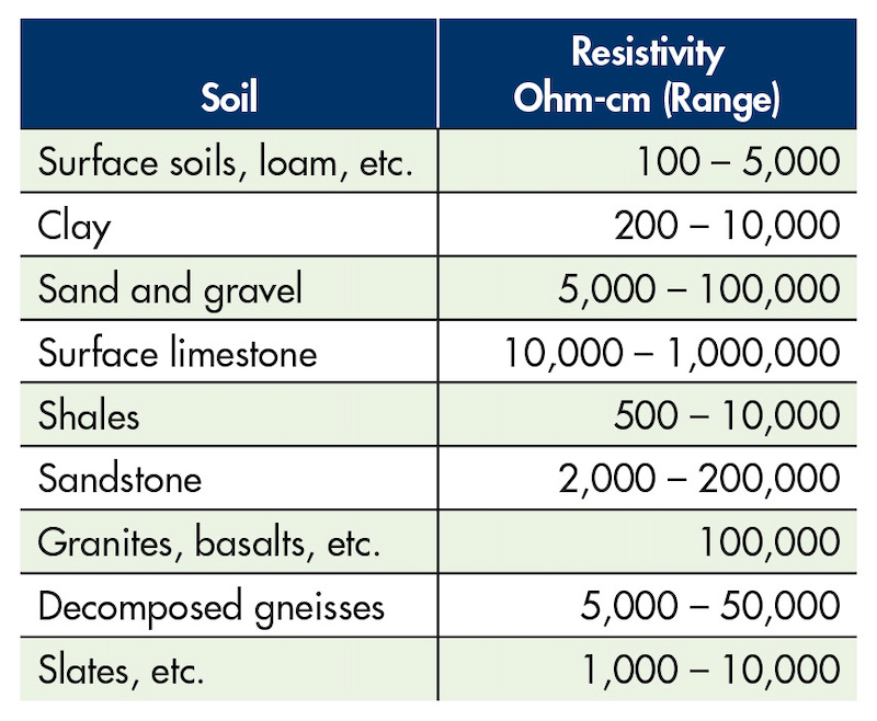
Table 1: Typical resistivity varies considerably with soil type.
GROUND RESISTIVITY TESTING
Earth surface potential gradients are critical in determining step-and-touch potentials around electrical facilities such as substations and assuring their safety in the event of extreme conditions like electrical faults. Ground electrode resistance is primarily a function of deep soil resistivity. Here, “deep soil resistivity” refers to depths roughly equivalent to the diameter of a horizontal electrode system or up to ten times the depth of a vertical electrode. Much more than surface resistivity, ground electrode resistance is critical to safety, fault clearance, and electrical performance.
Where a grounding system is to be installed, geotechnical work is often critical. Besides soil resistivity, this information may include soil layering, moisture content, soil pH, and depth of groundwater. While measuring resistance between two plates is sometimes used, it is not recommended to try to obtain soil resistivity from resistance measured between opposite faces of a soil sample due to unknown interfacial resistances between the sample and the electrodes being included.
A refinement of this crude technique is the measurement of samples in a specially designed box for the purpose, but this technique can be limited by the difficulty of acquiring a representative soil sample of such small volume, as well as duplicating soil compaction and moisture content. The method can still be useful if rigorously controlled and diligently applied, but alternative specialized methods have been developed to test soil resistivity in place.
VARIATION OF DEPTH METHOD
One of these alternative methods is variation of depth, or the three-point method. Here, ground resistance measurements are repeated in correlation with incremental increases in ground rod depth. This technique forces more test current through deep soil, and changes in resistivity can be noted at each depth. Driving rods also provides confirmation of how deep they can be driven during installation. A disadvantage, however, is that the rod may vibrate as driven, thereby reducing contact with soil and making conversion to true apparent resistivity less accurate.
The variation of depth method provides useful information about the soil in the vicinity of the rod, which is generally taken to be five to ten times the length of the rod. For large areas, it is useful to make multiple tests at representative locations to plot the lateral changes so that a resultant ground grid will not end up installed in soil of higher resistivity than was thought for the area.
The resistance of concern is designated r1. A series of three two-point measurements are taken, as the resistance between the electrode under test and each of two auxiliary electrodes, designated r2 and r3. The three measurements then would be r12 = r1 + r2, etc. The resistance of the test rod can then be calculated as
r1 = [r12 – r23 + r13]/2.
If the auxiliary electrodes are of materially higher resistance than the test electrode, this will greatly magnify the error of the test result. Therefore, the electrodes need to be far enough apart so as to minimize mutual resistances. Where inadequate distances have been used, absurdities such as zero and negative resistance can sometimes be calculated. Therefore, the auxiliary rods should be separated from the test rod by at least three times the depth of the test rod. The auxiliary rods should be driven to the same depth as the test rod, or even less. This method can become difficult to apply for large systems and where high accuracy is required, so other methods may be preferred.
FOUR-POINT METHODS
Four-point methods at one time were somewhat more difficult to run, principally involving more space and longer leads. In its crude form, the method requires a current source and a potentiometer or high-impedance voltmeter. But modern instrumentation has become quite sophisticated in helping the operator cut down steps and eliminate errors. Some instruments even graph the setup and perform the attendant math on screen. However, one thing that must be remembered when acquiring a test instrument is that it must be a four-terminal model. Three-terminal testers exist, for the purpose of performing ground resistance tests. For resistivity testing, a four-terminal model must be used.
Wenner Method
By far the most widely applied four-point method is the Wenner Method. This has been described in a previous article and will only be touched on here. The applicable tester has a Kelvin bridge configuration (Figure 1). Two outside current terminals apply the test current through the soil. Two inside voltage terminals measure the voltage drop between them, and the current and voltage parameters are used to calculate the resistance between the voltage probes, which is then shown on the display. The four probes are equidistantly spaced.
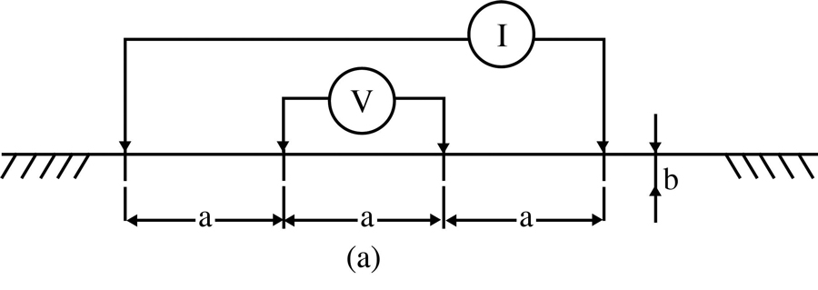
Figure 1: Probe Configuration for Wenner Method
The Wenner formula, 2πaR, where a is the distance between the voltage probes, is then used to calculate the resistivity, typically in units of Ω-cm, although other units of length can be used if desired. This is the average soil resistivity to a depth of a. The full Wenner formula is more complex, but simplifies to the aforementioned if a probe depth of 1/20th of a is used.
By systematically varying a, what is called vertical prospecting can be achieved. That is, the changes in resistivities at different depths can be plotted (Figure 2), aiding in the recognition of significant changes like bedrock.

Figure 2: Soil layering can be difficult to identify.
Though popularly used, the Wenner Method has two shortcomings.
1. Relatively large spacing between the two inner (potential) electrodes can cause a decrease in magnitude of potential. This might seem counterintuitive, but remember, the test current against which the voltage drop is being measured spreads out in all directions, not in a straight line as in a wire. Modern testers are increasing in sensitivity, which is helping to mitigate this disadvantage.
2. A second disadvantage is that Wenner requires the movement of all four probes in order to measure to varying depths. The walking back and forth can become prohibitive with large probe spacing.
Schlumberger Method
With the Schlumberger Method, the inner (potential) probes are placed closer together (Figure 3). Then only the outer probes are moved in order to calculate resistivity to varying depths.
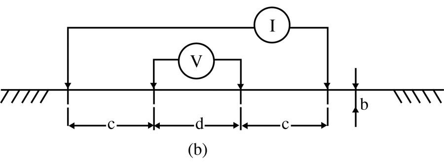
Figure 3: Probe Configuration for Schlumberger Method
If the depth of probes (b) is kept small in comparison to spacing (c and d) and c is greater than 2d, then resistivity can be calculated:
ρ = πc(c + d)R/d
This yields apparent resistivity to an approximate depth [2c + d]/2, which is the distance from the center of test to the outer current probes.
Confidence in results for both methods can be gained by repeating the tests with probes situated at 90 degrees to the prior set. Readings should be essentially the same. This will help eliminate underground interferences from water pipes, boulders, power lines, etc. from unduly influencing the measurements.
COMPARING METHODS
The variation of depth method can be used to calculate resistivities through the formula:
ρa =[R2πl]/[ln(4l/r)-1]
For each length (l) to which the tested rod is driven, the measured resistance value R determines the apparent resistivity value ρa. Here, r is merely the radius of the tested rod and is kept small with respect to l. Plotting R against l yields a visual aid for determining earth resistivity versus depth. Suppose this technique was used to plot the graphs shown in Figure 4. Figure 4a shows two distinct layers, a shallow one of around 300Ω-m and a deeper layer at 100Ω-m. An informative two-layer soil model is obtained. Figure 4b shows a relatively conductive shallow layer of 100Ω-m, but no data for the deeper layer can be determined by this method. Good conductivity at a deeper layer would be preferable for effective and reliable lightning and fault clearance, as surface conductivity can be volatile. And as already mentioned, variation of depth yields data for a relatively small area around the test rod. Gathering data for large grids may better be implemented by a four-point method.
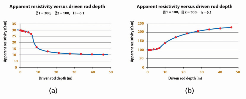
Figure 4: Changes in resistivity with depth can indicate soil layers.
Similarly, the results of four-point methods can be plotted as measured apparent resistivity against electrode spacing. Soil structure can be estimated from the resulting curves, but some empirical rules have been established by field workers to help in identifying layers.
• A break or change in curvature indicates another layer.
• The depth of a lower layer is taken to be two-thirds the electrode separation at which the inflection occurs.
• Five axioms may be followed:
1. Computed apparent resistivities are always positive.
2. As actual resistivities increase or decrease with depth, the apparent resistivities increase or decrease with probe spacings.
3. Maximum change in apparent resistivity occurs at probe spacing larger than depth at which the corresponding change in actual resistivity occurs. Therefore, the changes in apparent resistivity are always plotted to the right of the probe spacing corresponding to the change in actual resistivity.
4. The amplitude of the curve is always less than or equal to the amplitude of actual resistivity versus depth curve.
5. In a multilayer model, a change in actual resistivity of a thick layer results in a similar change in the apparent resistivity curve.
CONCLUSION
Resistance and resistivity measurements associated with grounding are particularly difficult and challenging because the earth is like no other electrical test item. A fundamental knowledge will cover most situations, but there’s always room to grow.
REFERENCE
IEEE Std 81-2012, IEEE Guide for Measuring Earth Resistivity, Ground Impedance, and Earth Surface Potentials of a Grounding System.
 Jeffrey R. Jowett is a Senior Applications Engineer for Megger in Valley Forge, Pennsylvania, serving the manufacturing lines of Biddle, Megger, and Multi-Amp for electrical test and measurement instrumentation. He holds a BS in biology and chemistry from Ursinus College. He was employed for 22 years with James G. Biddle Co., which became Biddle Instruments and is now Megger.
