
The rapidly developing industry of renewable power generation can be compared to an hourglass. Inexhaustible supplies of free resources — sun and wind — are converted into a corresponding outflow of electrical energy at notable return on investment. But the process includes the neck of the hourglass through which the resources must pass. This is the solar array or wind tower. These two assets must be diligently kept functioning at maximum efficiency and safety in order for the process to yield its anticipated return.
WIND
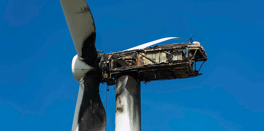
Wind towers are particularly at risk because of their great height: 280 feet and getting taller. It is estimated that a tower extending more than 50 feet above surrounding structures becomes a prime lightning target. Lightning interruptions cause up to 50% of typical downtime, depending on locale. And damage isn’t limited to structure. It can extend all the way down to sensitive control systems, further limiting profitability.
The National Lightning Safety Institute recommends that protection begin as early as site selection and proceed through system design. Yet the Institute estimates that maximum lightning protection can be achieved at only 1% of the total cost of a new project. Useful sources of standardization are available in IEC 61024 and IEC 61400-24.
SOLAR
Solar panels are at similar lightning risk as wind towers, as they are installed on roofs or vast open fields where they may be the highest structure.
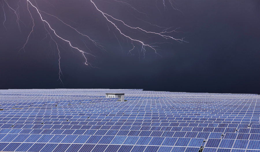
Open solar fields are prime lightning targets
The National Electrical Code (NEC) specifies:
Exposed non-current-carrying metal parts of module frames, equipment, and conductor enclosures shall be grounded.
Components like inverters, combiner boxes, and disconnects are connected by an equipment-grounding conductor. Every module must be connected to an equipment-grounding conductor. These converge commonly at the ground busbar inside the main distribution panel. From here, the grounding electrode conductor completes the connection to the ground electrode. When removing panels, care must be taken not to disrupt the bonding. For roof mounts, this is often rebar in the foundation, but it should be supplemented by a ground rod to prevent damage to the concrete during fault clearance. Full requirements are described in NFPA 70, NFPA 780, NEC Article 250, NEC Article 690, and UL 96A.
GROUNDING SYSTEM
The tower and array should be designed, constructed, installed, and maintained according to the highest industry standards. An indispensable part of this is the grounding. It is easy to become focused on the dynamics of this process, such as the turning of blades or the humming of transformers, and overlook the indispensable contribution made by the grounding system. Buried out of sight and not visibly operating, these critical components can be largely out of mind until an event occurs, such as a wind tower crashing to ground after a lightning strike.
Don’t wait for such an event to happen! Ensure the system is designed and installed in accordance with industry standards and local conditions first, and then periodically checked and maintained on a regular basis.
It is commonly thought that burying a rod and connecting the electrical system means it is grounded, but that is not necessarily the case. The grounding system must be treated with the same attention and care as any other electrical component.
GROUNDING CONDUCTOR
The other main element of this protection is the grounding conductor. No matter how good the grounding electrode (rod, grid, or other structure) is , it will be rendered useless without a continuous, low-impedance path to conduct lightning and fault current around equipment and personnel and safely into the soil. This is the job of the grounding conductor. In general applications, it connects the dead frame of equipment to the ground bus at the entrance panel.
But in wind generation, its structure is unique: It spans from the tips of the blades to connect with the ground grid at the base of the tower. Frequency of lightning strikes increases with height, and studies have suggested that rotating blade tips are additionally attractive.
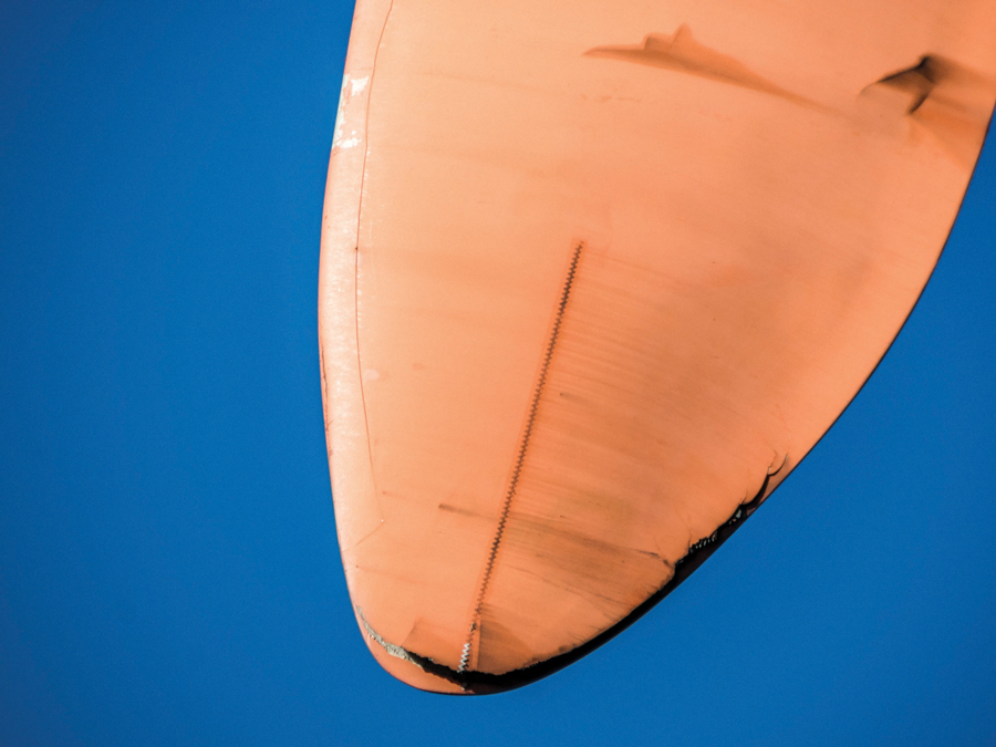
Blade tips are particularly vulnerable to lightning.
For adequate protection, the grounding conductor must be regularly tested. Turbine manufacturers typically specify 15–30 mΩ for a safe path to ground. A low-resistance ohmmeter is the designated tester for this purpose. Traditionally, these testers utilize a 10 Amp test current to reliably assure a sufficiently low-impedance path. These can be bulky, given the physical demands of this testing environment.
Recent improvements in meter technology, however, have made the job easier by introducing handheld 1 Amp testers with sufficient accuracy and resolution. The most sensitive part of the ground path is through the blade because the stress of motion can cause the grounding conductor to crack. If the two fragments remain in contact, a simple continuity test will still pass. A more robust test current and measurement resolution will unerringly reveal such a break.
But there’s still a unique problem: the distance of the blade tips from the ground. As with handheld testers, technological advances were in order and have been realized. Test leads with lengths of 100 meters have become available. The long leads create an additional problem: resistance. A compensation factor allows for power loss in some instruments when using leads of a normal length. Compensation for extra-long leads is accomplished via the formula:
P = I2R
Where:
P = output power of the instrument
I = output current of the instrument
R = (resistance of load) + (resistance of test leads)
Standard compensation in the average meter can fall short of delivering enough power against such a daunting lead resistance as would exist in 100-meter leads. Adequate compensation is achieved by reducing test current. Some instruments have a selector switch to reduce current; others do so automatically. Either way, a 1 amp test current has proven sufficient to yield accurate, reliable test results. The ohmmeter is thereby enabled to test with milli-ohm resolution without lead resistance entering the measurement.
REMOTE EARTH
The termination of the protection system is the electrode buried in earth. This must not be taken for granted. The mere fact of its existence is not enough, although it is often thought of in that manner. No, it must be tested, like any other electrical component. Surge arresters alone are inadequate without a good ground. The goal is low resistance to what is referred to as “remote earth” — that is, the maximum resistance a fault current or lightning stroke will encounter before being safely dissipated. There is no universal standard, but electrode resistance should be held to values like 1–5 Ω.
TESTING AND MAINTENANCE
Testing is particularly difficult with renewables because a single electrode is not grounding a single network, as in a building. Rather, potentially enormous numbers of wind towers and solar panels are daisy-chained together, and the chain is often growing. The biggest problem is that ground testing requires long leads strung to test probes far out in the soil, with the distances based on multiples of the maximum dimension of the grid or array. This can quickly become prohibitive. Unfortunately, there’s no simple answer. But one of the worst things to do is to wait until the job is done before testing. By that time, the composite electrode can be virtually too big to test.
Plan ahead, and test the sections as they are installed. This applies to both solar and wind, as the issue is the same. Every time a new section is paralleled in, resistance will drop significantly. So collectively, by the time the job is done, an adequate ground will be provided. Periodic maintenance also needs to be performed, as we’ve seen, and this can be a bigger challenge.
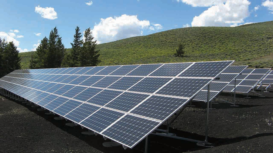
A Well-Maintained Solar Field
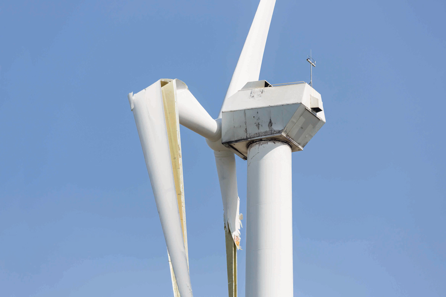
Wind Generator Blade Destroyed by Lightning
The most widely respected ground electrode test, fall of potential, is likely to require too much space. Be familiar with methods that have been specifically designed to deal with this problem. The most prevalent is the slope method. Another is intersecting curves. Instructions for these methods are commonly available in the literature. Additionally, lightning protection and power grounding have different criteria, so be certain requisite conditions are met for both. Power grounds may be shallow-buried, and this may not afford sufficient protection from lightning.
The grounding system must be tested upon installation for initial conformance to specs and standards, and then periodically thereafter. The familiar “out of sight, out of mind” can be deadly here. Clearance of lightning strikes and electrical faults will often work as intended, leaving the tower structure and function unharmed. But in the process of clearance, the grounding electrode can be seriously compromised, and it is dangerously out of sight. Regular testing, as well as after known strikes, is necessary. Changes in soil composition, especially moisture and subsurface corrosion, can have the same effect on a longer time scale.
Copper theft, a problem throughout the electrical industry, can be particularly acute on wind farms because of their size and remote location. In addition, grounding is often buried at much shallower depths than cabling, making theft that much easier. The clamp-on ground tester can be a useful tool here as a quick means of determining whether continuity exists or has been corrupted by theft.
Studious and thorough record-keeping is particularly in order, as comparing results can be especially informative in recognizing problems and issues. It’s also a good idea to note exactly where test probes are placed. Subsequent testing can then be done for comparison to stored records. The data is useful for maintenance to note changes, even if the size of the grid precludes objective accuracy to remote earth. Provided testing is precisely repeated, changes in results can be indicative of issues that need to be addressed.
CONCLUSION
Effective grounding is indispensable to the safe and efficient operation of renewable energy sources, wind towers, and solar arrays. The two are identical in requiring a continuous, low-impedance path to ground and a low-impedance connection to the surrounding earth. The test equipment is the same for both, and procedures are only slightly — but critically — adjusted to the site.
REFERENCES
Richard Kithil. “Lightning Hazard Reduction At Wind Farms,” National Lightning Safety Institute, 26 April 2010.
Paul Swinerd. Megger Application Note: “Earth Testing On Wind Farms”
Megger Application Note: “Testing Wind Turbine Lightning Protection.”
Bruce Thatcher. “Grounding: The Key To Lightning Protection,” Sankosha, USA. 2016.
Megger. “Getting Down To Earth: A Practical Guide to Earth Resistance Testing.”
 Jeffrey R. Jowett is a Senior Applications Engineer for Megger in Valley Forge, Pennsylvania, serving the manufacturing lines of Biddle, Megger, and Multi-Amp for electrical test and measurement instrumentation. He holds a BS in biology and chemistry from Ursinus College. He was employed for 22 years with James G. Biddle Co., which became Biddle Instruments and is now Megger.