

The purpose of the sync check function (25) is to ensure that the voltage magnitude, phase angle, and frequency of the generator (VX) and the utility system (VS) are within a set of acceptable limits before the generator is synchronized with the system via closing the circuit breaker that connects them (Figure 1).
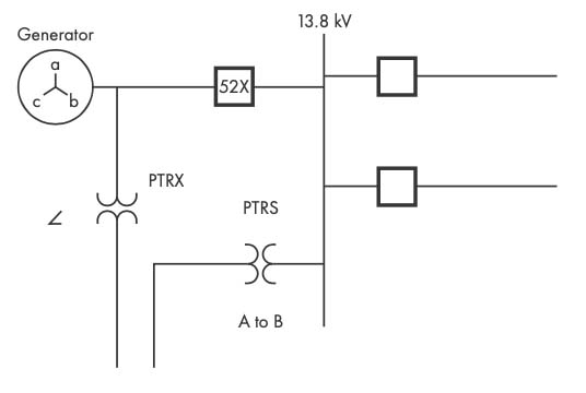
Figure 1: Sync Check Application Diagram
An improper sync can result in electrical and mechanical transients that damage the prime mover (for example, turbine), generator, GSU, and other vital power system components. Therefore, some users opt to externally supervise the sync check.
This article describes an application that uses two external relays to supervise the main sync check. Figure 2 shows the output contact arrangement for this scheme.
- R1 is the sync check output from the first supervisory relay.
- R2 is the sync check output from the second supervisory relay.
- 25 is the output from the sync check relay.
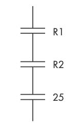
Figure 2: Double Supervision
All three must close simultaneously to allow a sync check.
R1 SETTINGS
Figure 3 shows the settings chosen for R1.
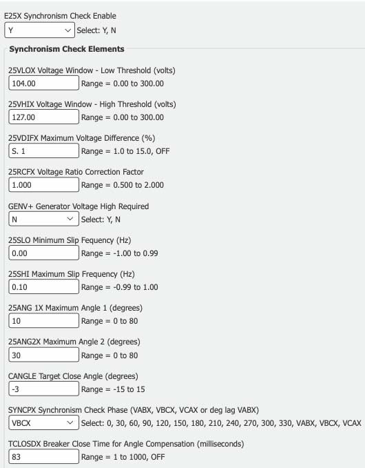
Figure 3: R1 Settings
E25X := Y # ENABLE SYNC CHECK FUNCTION
25VLOX := 104 V # LOW VOLTAGE THRESHOLD
25VHIX := 127 V # HIGH VOLTAGE THRESHOLD
25VDIFX := 5.1% # MAXIMUM VOLTAGE DIFFERENCE
GENV+ := N # GENERATOR VOLTAGE HIGH REQUIRED
25SLO := 0.00 # MINIMUM SLIP FREQUENCY (Hz)
25SHI := 0.10 Hz # MAXIMUM SLIP FREQUENCY
25ANG1X := 10 degrees # MAXIMUM ANGLE 1
TCLOSDX := 83 ms # BREAKER CLOSE TIME (milliseconds)
R2 SETTINGS
Figure 4 shows the settings chosen for R2. These settings correspond directly to R1; however, it does not provide as much control. Therefore, R1 must be set to match R2.
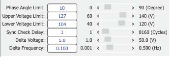
Figure 4: R2 Settings
COMMISSIONING ANALYSIS
Voltage Magnitude
The scheme was a live system tested to ensure it will work properly during synchronization. Figure 5, Figure 6, and Figure 7 show the measured voltage during these tests. VAB is the generator potential while VX is the system potential. Review of Figures 5 through 7 shows that the magnitudes of VAB and VX are almost identical (that is, matched).
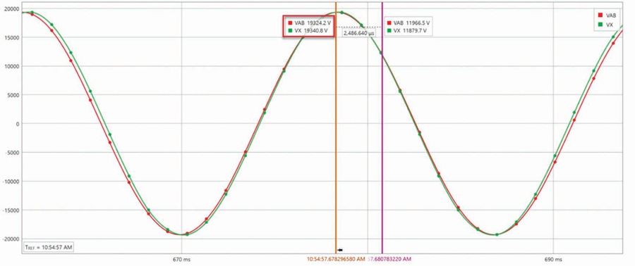
Figure 5: COMTRADE Record 1
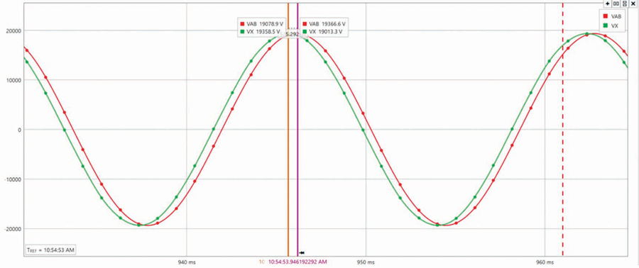
Figure 6: COMTRADE Record 2
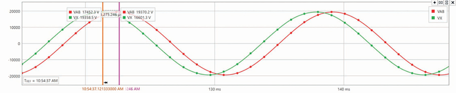
Figure 7: COMTRADE Record 3
Originally, R1 was set so that a sync was only allowed when the generator potential magnitude was greater than the system. However, R2 does not provide this functionality if the generator potential magnitude is greater than the real power flows out of the machine into the system, which prevents motoring on startup.
Figure 8 shows the voltage comparison (VDIF and VENX) logic for R1. The voltage difference logic includes the GENV+ input and that this must be true for at least three cycles before VENX asserts and enables the angle comparison calculation. Therefore, 25AX1, 25AX2, and 25C cannot assert if VENX is not true. As previously noted, R2 does not have this logic, so this functionality was lost.
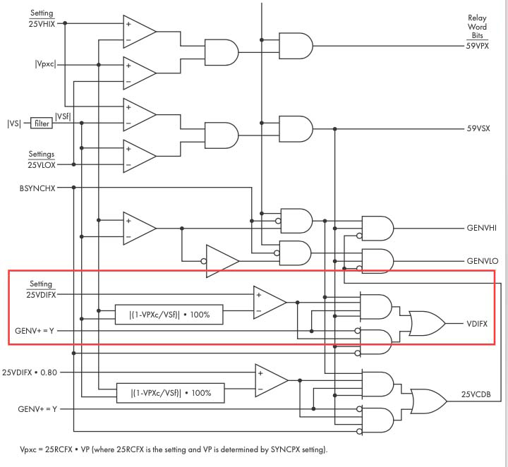
Figure 8a: R1 Logic
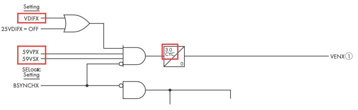
Figure 8b: R1 Logic
Slip Frequency
We can estimate the slip frequency by measuring the time (period) between zero crossings.
System frequency = 1/0.016667 = 59.999 Hz (Figure 9)
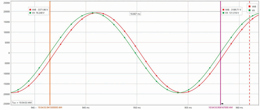
Figure 9: System Frequency
Generator frequency = 1/ 0.016648 = 60.067 Hz (Figure 10)
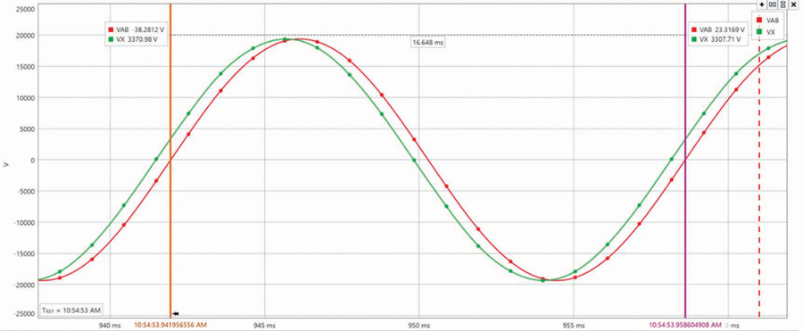
Figure 10: Generator Frequency
Therefore, the slip frequency is 60.067 – 59.999 = 0.068 Hz.
SUMMARY
Using two different relays to supervise sync check means that some of the overall functionality is lost since they do not completely duplicate each other. For example, the GENV+ setting originally blocked closing since the voltages are matched, so this function had to be disabled. Matching settings results in much more consistent performance between the two relays.
 Steve Turner is in charge of system protection for the Fossil Generation Department at Arizona Public Service Company in Phoenix. Steve worked as a consultant for two years, and held positions at Beckwith Electric Company, GEC Alstom, SEL, and Duke Energy, where he developed the first patent for double-ended fault location on overhead high-voltage transmission lines and was in charge of maintenance standards in the transmission department for protective relaying. Steve has BSEE and MSEE degrees from Virginia Tech University. Steve is an IEEE Senior Member and a member of the IEEE PSRC, and has presented at numerous conferences.