
The high level of penetration of distributed energy resources (DERs) is one of the main characteristics of the smart grid, and it requires a different approach to the protection of the grid. IEC 61850 is widely accepted around the world due to the significant benefits it provides compared with conventional hardwired solutions. However, many specialists in the industry still hesitate to start using Generic Object Oriented Substation Event (GOOSE) messages for all protection and protection-related functions. This is due mainly to lack of understanding of the differences between hardwired and GOOSE-based solutions. Taking advantage of the benefits is possible only when the fundamentals and applications are well understood.
This article first introduces the concepts of the IEC 61850 GOOSE (generic object oriented substation event).
- Publisher and subscriber functionality
- Multicasting
- Event reporting versus commands
- Repetition mechanism
- Data sets
- Simulation bit
Routable GOOSE (R-GOOSE) is presented later, followed by discussion of several use cases describing application of R-GOOSE technology for reducing fault clearing time.
GOOSE Communications
Peer-to-peer is the characteristic communications type for IEC 61850-based systems. It is one of the distinguishing features of the standard that makes it attractive to protection and control specialists. It describes the ability of arbitrary pairs of intelligent electronic devices (IEDs) connected to the substation network to manage the exchange of information as necessary with all devices having equal rights, in contrast to master/slave communication. High-speed, peer-to-peer communications in IEC 61850-based protection and control systems use a specific method designed to meet a variety of requirements. It is very important that the concept of the generic substation event (GSE) model is not based on commands, but on the sending indication by a function that a specific substation event has occurred. It is designed to support reliable high-speed communications between different devices or applications and allows the replacement of hardwired signals between devices with communication message exchange while improving the functionality of the protection, automation, and control system. It uses a connectionless publisher–subscriber communications mechanism shown in Figure 1.
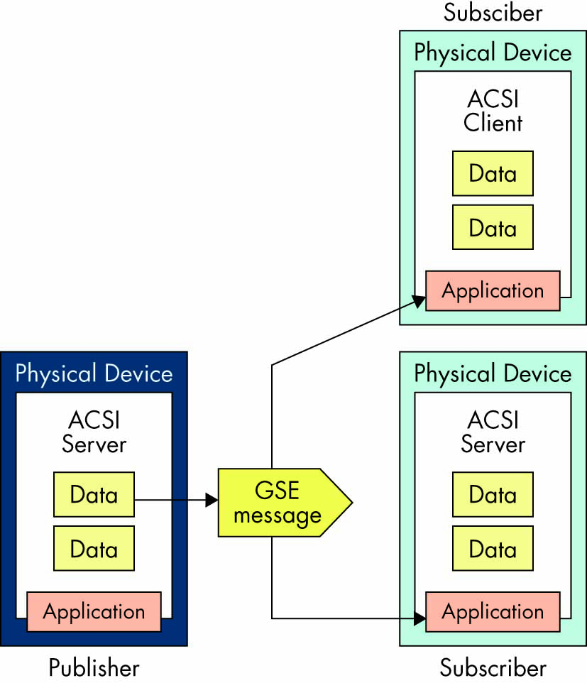
Figure 1: Publisher/Subscriber Mechanism
The model includes several features that can be used to improve the reliability and availability of the system. At the same time, the proper use of these features in a vendor’s implementation will reduce maintenance and increase the flexibility of the system. GOOSE was initially developed for substation communications, but due to the benefits it provides, there is a need to define how it can be used for substation-to-substation or wide-area communications.
To understand the differences between substation GOOSE and wide-area GOOSE, we need to look into some of the details of the generic substation event (GSE) model. The GSE method is considered a mechanism for reporting by a logical device. The achievement of speed, performance, availability, and reliability depends on the implementation in any specific device.
The GSE model is used to exchange the values of a collection of data attributes defined as a data set (Figure 2). GOOSE supports the exchange of a wide range of data types organized in a data set.
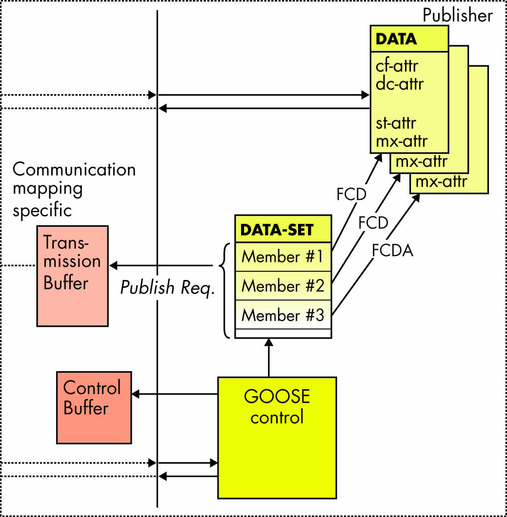
Figure 2: Publisher Functionality
The publisher writes the values in a transmission buffer at the sending side and multicasts them over the substation local area network to the various subscribers — clients or servers.
The data in the published GOOSE messages is a collection of values of data attributes defined as members of a data set. The receiver reads the values from a local buffer at the receiving side. A GSE control class in the publisher is used to control the process. If the value of at least one of the data attributes has changed, the publisher’s transmission buffer is updated with the local service publish, and the values are transmitted with a GOOSE message.
The publisher/subscriber mechanism allows the source IED to reach multiple receiving IEDs, thus significantly improving the efficiency of the communications interface. In substation communication networks, this is based on the use of a media access control (MAC) multicast destination address in the Ethernet frame shown in Table 1.
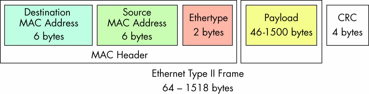
Table 1: Ethernet Type II Frame
Where:
- Destination address (6 bytes) identifies which station(s) should receive the frame.
- Source address (6 bytes) identifies the sending station.
- Length is 6 octets and contains the value of the destination MAC address to which the GOOSE message is to be sent. The address must be an Ethernet address that has the multicast bit set TRUE.
- If a port has an 802.1Q-compliant device such as another switch attached (such as another switch), these tagged frames can carry virtual local area network (VLAN) membership information between switches, thus letting a VLAN span multiple switches.
- Specific communication services in the subscribers update the content of their reception buffers, and new values received are indicated to the related applications.
Since the GOOSE messages replace hardwired signals used for protection and control applications, IEC 61850 introduces mechanisms that ensure delivery of the required information.
Once a new value of a data attribute has resulted in the multicasting of a new GOOSE message, the repetition mechanism ensures that the message is sent with a changing time interval between the repeated messages until a new change event occurs.
As shown in Figure 3, the interval immediately after a change is very short — a few milliseconds — which later increases until it reaches a value of a few seconds. This method achieves several important tasks:
- Ensures that loss of a single message will not affect the functionality of the system.
- Allows any new device to inform all subscribing devices about its state.
- Allows any new device to learn the state of all publishing devices it subscribes to.
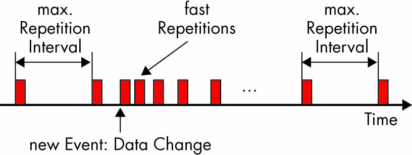
Figure 3: GOOSE Repetition Mechanism
The GOOSE messages contain information that allows the receiving devices to know not only that a status has changed, but also the time of the last status change. This allows a receiving device to set local timers relating to a given event.
At the same time, the repetition mechanism can be used as a heartbeat that allows the continuous monitoring of the communications interface — something that is not possible in conventional hardwired systems.
The state number and the sequence number can be used to detect intrusion, thus allowing significant improvement in the cyber security of the system without the need for encryption or other cyber security methods.
The GOOSE control block class defined in Edition 1 of IEC 61850 (Figure 4) includes the attributes that define the behavior of peer-to-peer communications and is related to a logical device — and more specifically, to its Logical Node Zero (LLN0).
- GoCBName (GOOSE control name) identifies a GoCB within the scope of a GoCBRef (GOOSE control reference) — a unique path name of a GoCB within LLN0: LDName/LLN0.GoCBName.
- GoEna (GOOSE enable) indicates that the GoCB is enabled (if set to TRUE) to send GOOSE messages. If set to FALSE, it will stop sending GOOSE messages.
- AppID is an application identification represented by a visible string that represents a logical device in which the GoCB is located.
- DatSet is the reference of the data set whose values of members shall be transmitted.
- ConfRev is the configuration revision indicating the number of times the configuration of the data set referenced by DatSet has been changed. The counter is incremented every time the configuration changes.
- NdsCom (needs commissioning) is TRUE if the attribute DatSet has a value of NULL and is used to indicate that the GoCB requires configuration.
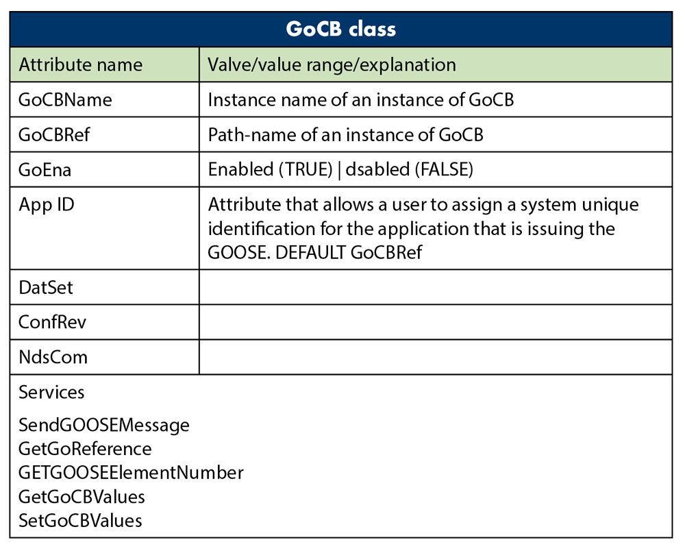
Figure 4: GOOSE Control Block Class
As already mentioned, the content of the GOOSE message (Figure 5) allows receiving devices to process the data in order to execute required actions. Some of the attributes in the GOOSE message that help perform the functions described earlier are:
- T is the time stamp representing the time at which the attribute StNum was incremented.
- StNum indicates the current state number — a counter that increments each time a GOOSE message (including a changed value) is sent for the first time. The initial value is 1.
- SqNum is the sequence number — the value of a counter that increments each time a GOOSE message with the same values has been sent. The initial value is 1.
- Simulation is a parameter that indicates that the GOOSE message is used for test purposes (if the value is TRUE) and that the values of the message have been issued by a simulation unit and shall not be used for operational purposes.
- The GOOSE subscriber reports the value of the simulated message to its application instead of the real message depending on the setting of the receiving IED.
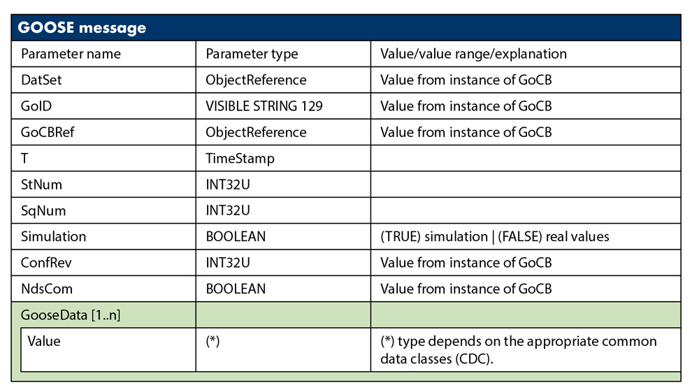
Figure 5: GOOSE Message
This basic concept also applies to the GSSE model, which is similar to the GOOSE model. However, there are two major differences:
- GOOSE provides flexibility in the definition of a data set with different data types, while GSSE provides only a simple list of status information.
- GOOSE mapping to IEC 61850 8-1 supports VLAN and priority tagging.
R-GOOSE
The GOOSE message was designed for peer-to-peer substation communications and therefore uses a three-layer stack and MAC multicast. This is not suitable for messages that need to be sent over a wide-area network. For that reason, Technical Report IEC 61850 90-5, Use of IEC 61850 to transmit synchrophasor information according to IEEE C37.118 selected UDP/IP as the option to transmit data over arbitrary large distances.
Internet Protocol (IP) is a Layer 3 protocol. The network layer adds the concept of routing above the data link layer. When data arrives at the network layer, the source and destination addresses contained inside each frame are examined to determine if the data has reached its final destination. If that is true, Layer 3 formats the data into packets delivered up to the transport layer. IP allows the routing of data packets (IP packets) between different networks over any distance.
User Datagram Protocol (UDP) is a transport Layer 4 network protocol. While Transmission Control Protocol (TCP) is a connection oriented protocol that requires communications between a client and a server to first be established, UDP is connectionless, which makes it more suitable for GOOSE communications.
UDP network traffic is organized in the form of datagrams. A datagram comprises one message unit. The first eight bytes of a datagram contain header information; the remaining bytes contain message data.
A UDP datagram header consists of four fields of two bytes each:
- Source port number
- Destination port number
- Datagram size
- Checksum
UDP checksum protects the message data from tampering. The checksum value represents an encoding of the datagram data calculated first by the sender and later by the receiver. If the checksum does not match, indicating tampered or corrupted data during transmission, the UDP protocol detects it. In UDP, the checksum is optional as opposed to TCP, where it is mandatory.
Many working applications of the IEEE C37.118 protocol confirm that the use of UDP for streaming of the synchrophasor data is a proven method that can also be used for the routable GOOSE.
Considering the importance of the checksum as a cyber security tool, IEC 61850 8-1 Edition 2.1 defines it as mandatory for IEC 61850 implementations. Table 2 shows the UDP field implementation requirements defined in the standard.
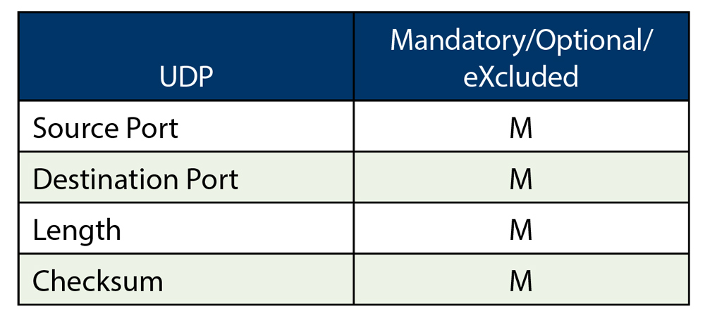
Table 2: UDP Field Implementation Requirements
R-GOOSE Applications in Smart Grid
R-GOOSE may have many different applications. It can be used for complex hierarchical system integrity protection schemes (SIPS) at the system’s transmission level in order to communicate the change of state of system components that impact the stability of the system. It also can be used by the SIPS to send GOOSE messages to the system components that are used to execute the required actions.
At the system’s distribution level, the R-GOOSE can be used very successfully for distribution automation applications. It can also play a critical role in smart grids with high penetration of distributed energy resources (DERs).
Distributed generators are typically connected to sub-transmission or distribution systems. The definition of such systems varies between utilities, and in some cases, systems with voltages as high as 138 kV may be considered as distribution. The addition of distributed generators has a significant effect on the system (Figure 6). It affects the levels of short-circuit currents, the dynamic behavior of the system following such faults, and the coordination of protective relays and must be considered when selecting the protection system. Line protection settings and criteria should take into account in-feed effect, possible power swings, and generator out-of-step conditions.
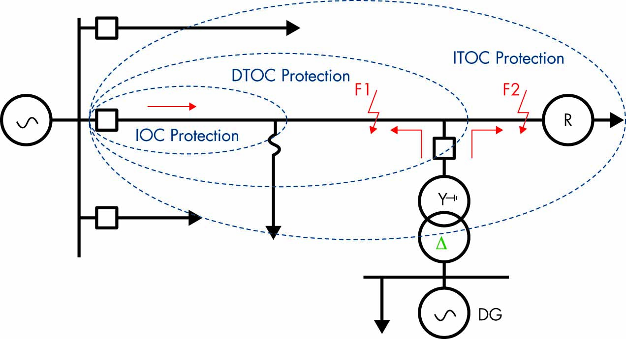
Figure 6: Distribution Feeder with DG
The increased fault clearing times caused by the in-feed effect of a distributed generator may not be acceptable to customers with sensitive loads. The voltage sag is experienced not only by users on the faulted feeder, but also on adjacent feeders connected to the same distribution system.
Figure 7 shows the areas impacted by voltage sags or swells on sensitive equipment and demonstrates that the impact depends on two characteristics. The first characteristic of a voltage sag — the depth — is a function of the type of fault, fault location, and system configuration. It will also be affected by the state of the distributed generator — whether it is in service or not. Single phase-to-ground faults lead to voltage sag in the faulted phase and to voltage swell in the healthy phases. The level of voltage increase is also affected by the grounding of the interface transformer and must be taken into consideration.
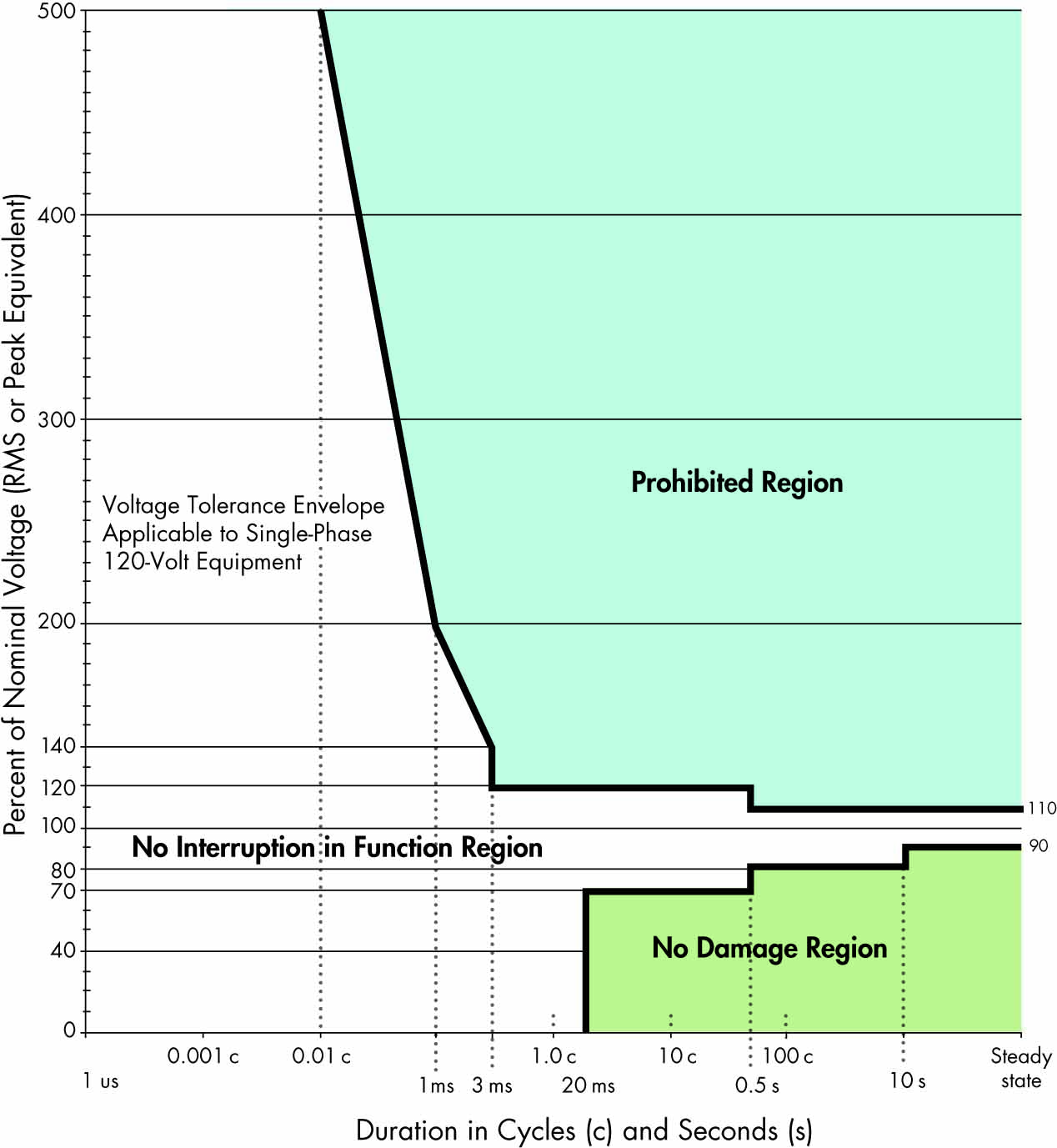
Figure 7: ITIC (formerly CBEMA) Curve
The same two fault characteristics also have an impact on the ride-through capability of the DER. Figure 8 shows an example of a ride-through characteristic. This is something we can’t control, but we must study it in order to be able to predict or estimate the effects of different faults on sensitive equipment.
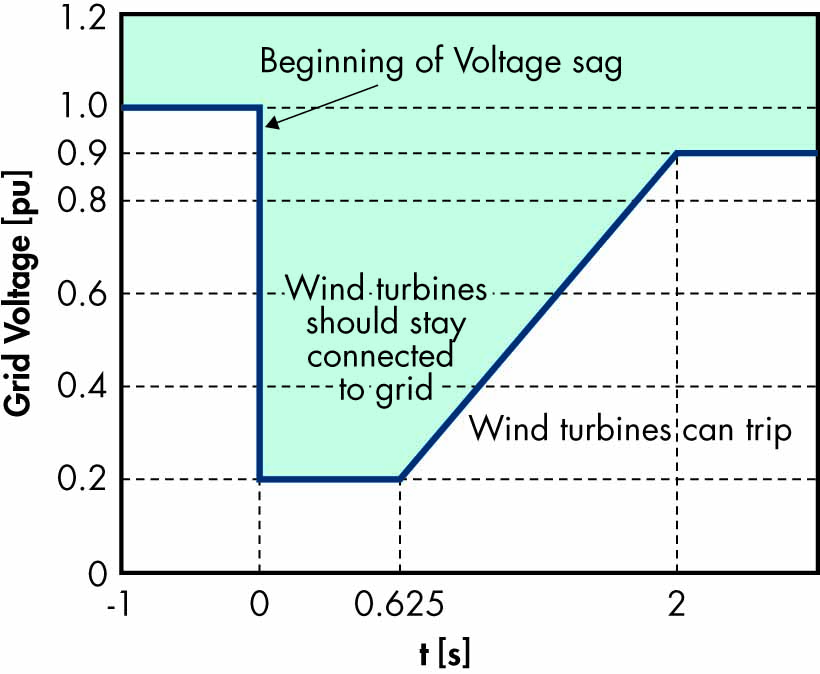
Figure 8: Ride-Through Characteristic
The second characteristic of the voltage sag — duration — is the parameter we can control by properly applying the advanced features of multifunctional protection relays.
Distributed generator interconnection protection has been the subject of many papers, as well as standardization work such as IEEE P-1547 (Figure 9). It is clear that the location of the fault and the in-feed from the generator will lead to increased fault clearing time and coordination problems. This depends more specifically on the type of distributed generator and its interconnection with the electric power system.
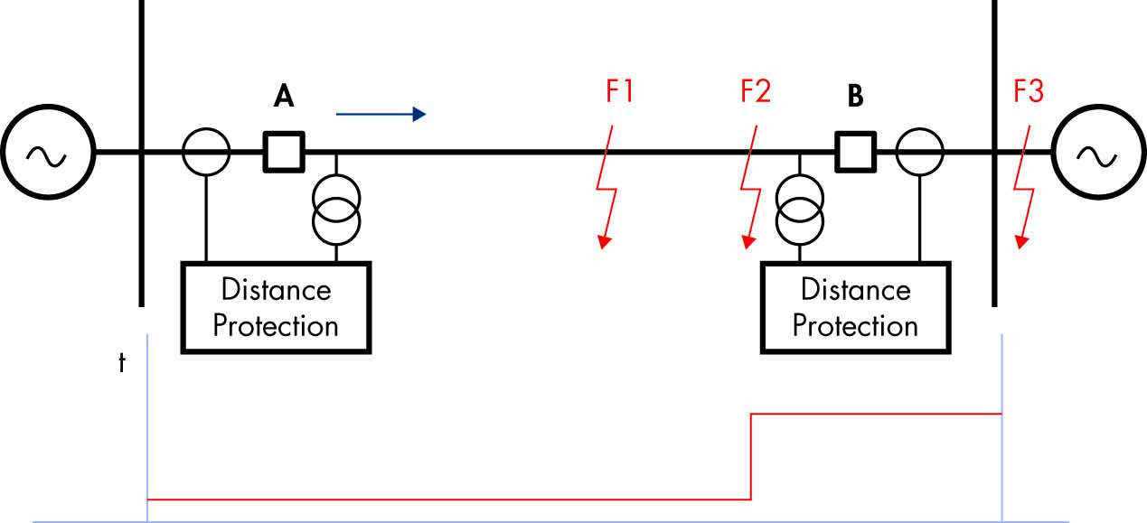
Figure 9: Distance Protection of Transmission Line
However, it is not only distribution feeder protection that needs to be accelerated. When a short-circuit fault occurs on a transmission line connected to a substation with DERs connected at the distribution level, the voltage drop caused by the fault must be considered in analyzing the performance of the DER and its ability to ride through the fault.
When the fault is in Zone 2 of the protected transmission line (especially on shorter lines), the time delayed trip will depend on the time delay setting, which may be in the range of 300–400 msec. Such a delayed trip will impact the duration of the voltage sag experienced by a DER in the tripping area of the ride-through characteristic. An accelerated protection scheme can significantly reduce fault clearing time and bring it within the stay-connected area of the characteristic.
Accelerated Line Protection Schemes
Conventional distance protection does not provide instantaneous tripping for all faults on a protected transmission line. Communications-based accelerated schemes allow considerable improvement in overall fault clearing time for any fault within the zone of protection. At the same time, they do not have the high-speed communication requirements line differential protection has. This is due to the fact that these schemes use a signaling channel to transmit simple ON/OFF data from a local protection device. This provides additional information to the remote-end protection device that can be used to accelerate in-zone fault clearance or prevent operation for external faults. These teleprotection schemes can be grouped into three main operation modes.
In each mode, the decision to send a command is made by a local protective relay operation:
- In intertripping, (direct or transfer tripping) applications, the command is not supervised at the receiving end by any protection function and simply causes a breaker trip operation. Since no checking of the received signal is performed, it is absolutely essential that any noise on the signaling channel isn’t seen as being a valid signal. In other words, an intertripping channel must be very secure.
- In permissive applications, tripping is only permitted when the command coincides with a protection operation at the receiving end. Since this applies a second, independent check before tripping, the signaling channel for permissive schemes does not have to be as secure as for intertripping channels.
In blocking applications, tripping is only permitted when no signal is received, but a protection operation has occurred. In other words, when a command is transmitted, the receiving end device is blocked from operating even if a protection operation occurs. Since the signal is used to prevent tripping, it is clear that a signal must be received whenever possible and as quickly as possible. In other words, a blocking channel must be fast and dependable.
The protection function that sends the permissive or blocking signal to the remote end determines the type of scheme used. If this is a distance element, we usually talk about permissive underreaching or overreaching schemes or blocking schemes. If a directional element is used to initiate the transmission of a signal to the remote end of the protected line, we have directional comparison schemes. A directional comparison scheme can be permissive or blocking, with directional elements initiating signal transmission and providing supervision at the receiving end.
As an example of an accelerated transmission line protection scheme, consider a permissive directional comparison scheme commonly used to accelerate the clearing of all kinds of faults, including high-resistance faults that are not seen by the distance elements of the transmission line protection relays or line differential relays (Figure 10).
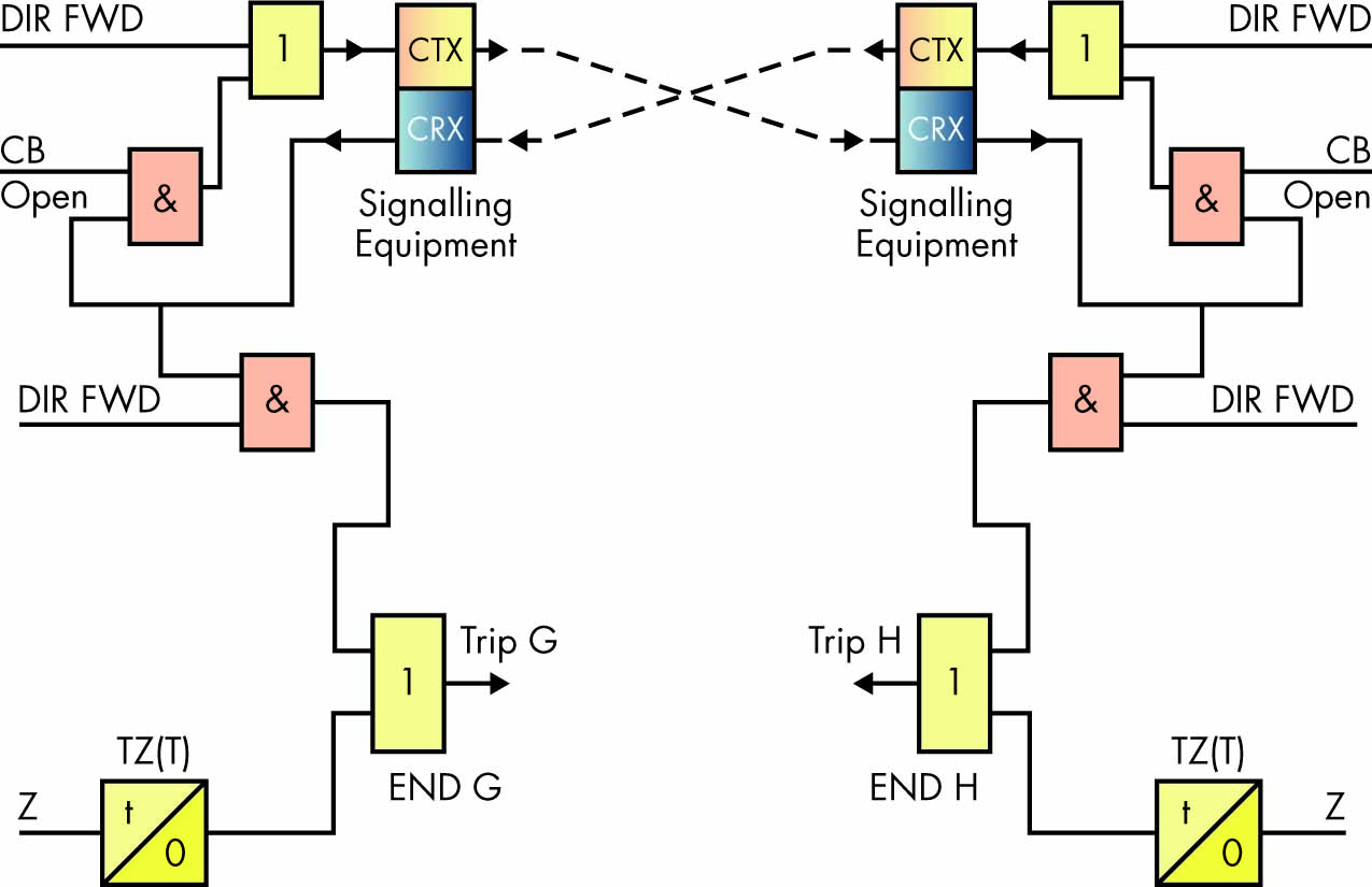
Figure 10: Permissive Directional Comparison Scheme
The channel for a directional comparison permissive scheme is keyed by operation of the forward-looking elements of the relay. If the remote relay has also detected a forward fault upon receipt of this signal, the relay will operate. Such schemes offer significant advantages, especially when high-speed directional detection methods based on superimposed current and voltage components are used.
Permissive schemes tend to be more secure than blocking schemes because forward directional decisions must be made at both ends of the line before tripping is allowed. Failure of the signaling channel will not result in unwanted tripping because no signal is going to be received, and the relay does not trip based on a forward directional detection only.
If the source at either end of the line is weak, the directional comparison permissive scheme uses weak infeed logic.
Current reversal guard logic is used to prevent healthy line protection maloperation for the high-speed current reversals experienced in double circuit lines caused by sequential opening of circuit breakers.
If the signaling channel fails, basic distance scheme tripping will usually be available.
The challenge for the implementation of accelerated transmission line protection schemes is that they require a communications channel which, if it is dedicated, will require additional costs. IEC 61850 R-GOOSE messages are a technology that can help us achieve these goals without the need for additional investments.
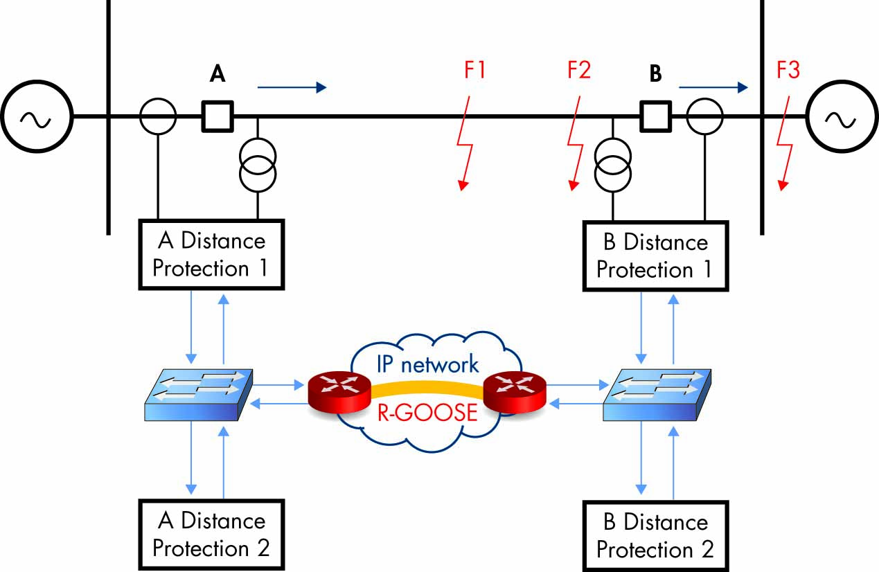
Figure 11: Accelerated Protection with R-GOOSE
Conclusion
R-GOOSE is a version of the popular IEC 61850 peer-to-peer communications method that can be used for wide-area protection and control applications. While the principles remain the same, R-GOOSE uses UDP multicast as the transport mechanism. R-GOOSE offers significant benefits for many different electric power system protection, automation, and control applications, including:
- System integrity protection schemes at the transmission level
- Distribution automation systems
- Accelerated transmission line protection schemes
- Accelerated distribution protection schemes
Such applications will have a positive impact on the efficiency of the protection and control systems in smart grids.
 Dr. Alexander Apostolov is presently Principal Engineer for OMICRON electronics Corp. USA in Los Angeles. He has 42 years of experience in power systems protection, automation, control and communications. Alex holds four patents, has authored and presented more than 500 technical papers, is editor-in-chief of PAC World, and is an IEEE distinguished lecturer and adjunct professor at the Department of Electrical Engineering, Cape Peninsula University of Technology, Cape Town, South Africa. He is an IEEE Fellow and a member of the Power Systems Relaying Committee and Substations C0 Subcommittee; is past chair of the Relay Communications Subcommittee; serves on many IEEE PES working groups; and chairs WG C2 Role of Protective Relaying in Smart Grid. He is a member of IEC TC57 Working Groups 10, 17, 18, and 19, and leads the Task Force for Functional Testing of IEC 61850 Based Devices and Systems. He is a Distinguished Member of CIGRE; Convenor of CIGRE WG B5.53, Test Strategy for Protection, Automation and Control (PAC) functions in a full digital substation based on IEC 61850 applications; and a member of several other CIGRE B5 working groups. Alex received his MS in electrical engineering, MS in applied mathematics, and PhD from the Technical University in Sofia, Bulgaria.