

An out-of-phase synchronization (OOPS) event results in a torque transient on the generator and prime mover. It exposes the generator, generator step-up (GSU) transformer, and system elements to a current transient that puts mechanical and thermal stresses on windings and other conductors.
These transients can be significant and result in through-current magnitude equivalent to a three-phase fault located at the terminals of the generator. Since damage due to mechanical stresses tends to be cumulative, it is important to detect these occurrences and clear the condition as quickly as possible. This article explores the phenomena and demonstrates how to program two generator protection relays to provide OOPS protection.
OOPS PROTECTION SCHEME LOGIC
The scheme requirements for an OOPS event are not onerous, and in the interest of accurate targeting, a dedicated scheme is warranted. Traditional generator protection cannot typically detect OOPS events. Generally, most elements that might be responsive to the high currents during an OOPS event are time-delayed, and high-speed differential elements are blind to this event. The inadvertent energization element is typically disarmed by the presence of voltage, thus disabling the element during an OOPS event. Furthermore, an OOPS event can continue to occur every time a generator is synchronized until the underlying cause is addressed.
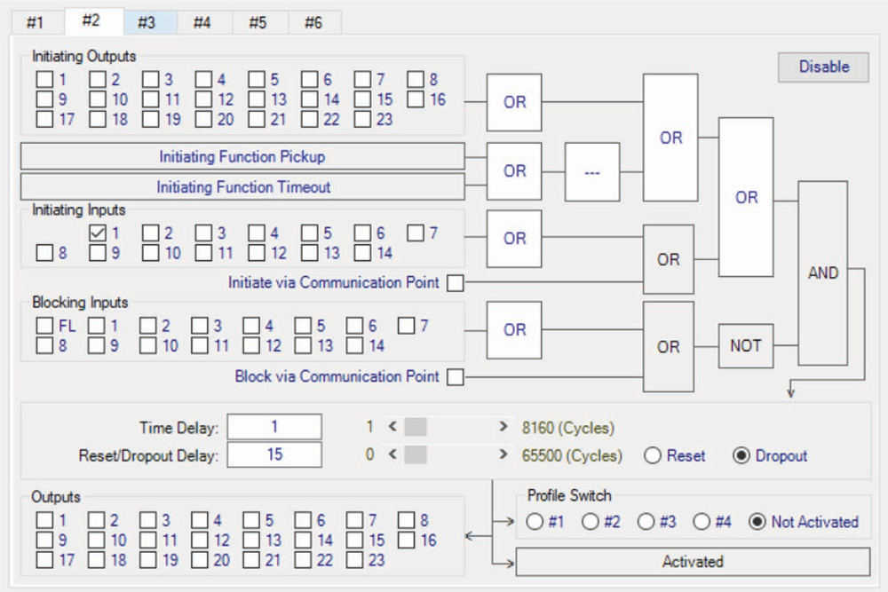
The protection scheme logic (Figure 1) is simple and given as follows:
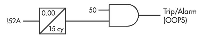
The 50 element should not be enabled while machines are online due to the inability to coordinate the element with other protective systems. An OOPS event, however, results in a high current magnitude at the instant of breaker closure. Use a 52A status signal, in conjunction with a timer set for a 15-cycle dropout delay, to disable the overcurrent element 15 cycles after the breaker closes. This condition must be cleared immediately because zero crossings may stop if the condition persists. Hence, no additional time delay is provided and the element should trip instantly. This scheme also detects and trips high-speed for the slow breaker close OOPS scenario.
The maximum AC that occurs during an out-of-phase sync is calculated as follows:
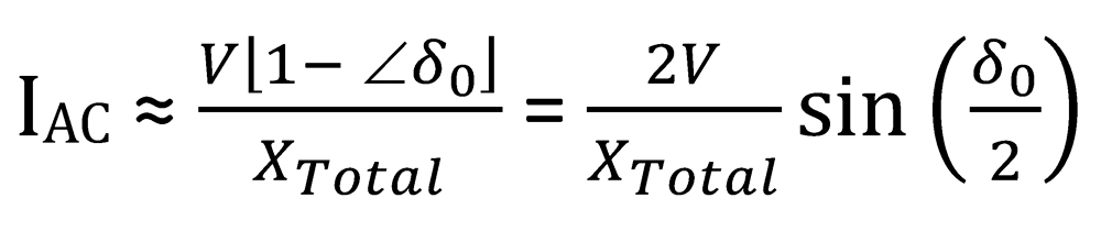
where:
IAC ≡ maximum AC magnitude
V ≡ generator and system voltage magnitudes (typically one per unit)
XTotal ≡ sum of Xd”, XT, and XS
δ0 ≡ synchronizing angle across the breaker
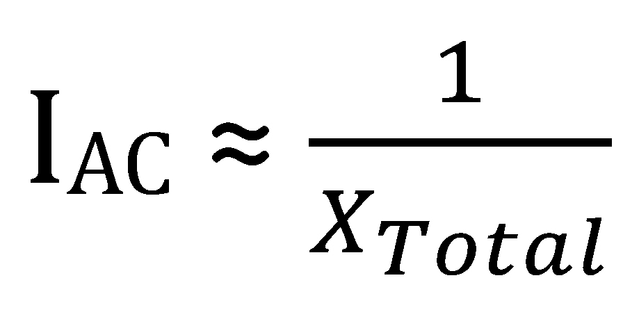
Typically, an angle of 60 degrees is chosen to determine the current magnitude. The pickup setpoint for this protective element should be sensitive enough to detect an OOPS event and also high enough that it does not inadvertently operate on an acceptable synchronization. Equation [1] can be expressed as follows assuming an angle of 60 degrees and one per unit voltage magnitudes:
REAL LIFE EXAMPLE FOR A COMBUSTION TURBINE GENERATOR (CTG)
In 2023, an electric utility experienced an out-of-phase sync (OOPS) event for a custom turbine generator (CTG). Here is the 50-phase overcurrent protection function and logic needed to configure the generator protection relays for the CTG, where the event occurred.
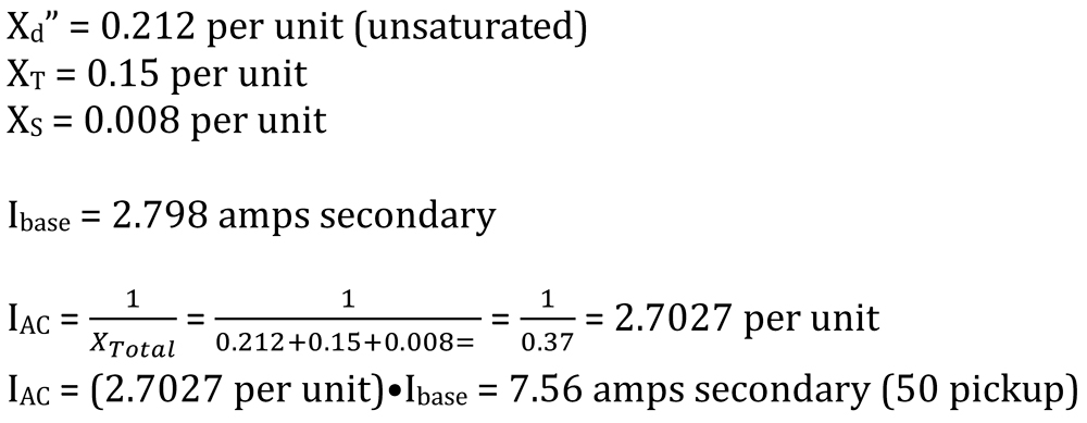
CTG AC Current Calculations (Generator Base):
M-3425A RELAY
Using this information, here are the settings for an M-3425A relay.
Phase Overcurrent Pickup

IPSlogic
SEL-700G RELAY
Using this information, here are the settings for a SEL-700G relay.
Phase Overcurrent Pickup
50PX2P = 7.56 Amps secondary
50PX2D = 0
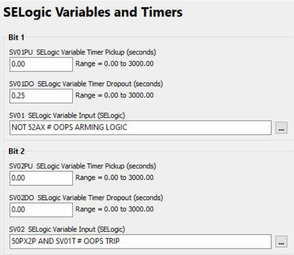
SELogic Control Equations
TR1 := 21C1T OR 21C2T OR SV08T OR 64G1T OR 87R OR 87U OR SV02T
# TRIP LOCKOUT 4C86G-1
TR2 := 24C2T OR (3PWRX1T AND NOT LOPX) OR 40Z1T OR 40Z2T OR 46Q2T OR
(59PPX1T OR 59PPX2T) AND 52AX OR OOST OR 81X4T OR SV02T
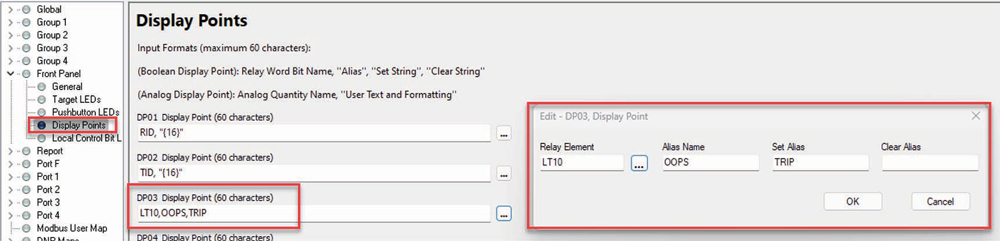
Program the SEL-700G to display an alarm when an OOPS trip has occurred as follows:
SET01 := SV02T
RST01 := TRGTR
Latch bit LT01 remains asserted until personnel presses the Target Reset pushbutton. This latch is programmed as a display point as follows:
OSCILLOGRAPHY
Oscillography captured by one of the generator protection relays for the event described in the introduction is presented in Figure 6.
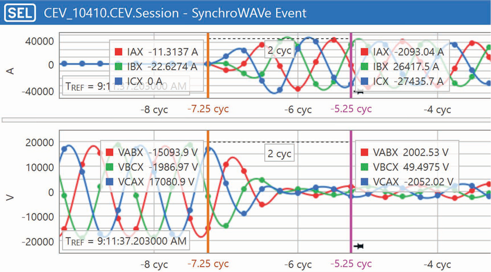
The stator phase current grew extremely high in magnitude when the generator circuit breaker (GCB) was closed out of phase. The filtered current on C-phase recorded by the generator protection relay rose as high in magnitude as 29,650 Amps. A three-phase fault at the terminals of the CTG would produce 28,335 Amps based upon the saturated subtransient reactance (Xd”) of 0.158 per unit and a nominal current of 4,477 Amps. Based on IEEE Std. C50.13, IEEE Standard for Cylindrical-Rotor 50 Hz and 60 Hz Synchronous Generators Rated 10 MVA and Above, generators are built to withstand a three-phase fault at the terminals. The current magnitude produced during the out-of-phase close exceeded the three-phase fault current. The generator bracing was inspected to verify it was still intact.
CONCLUSION
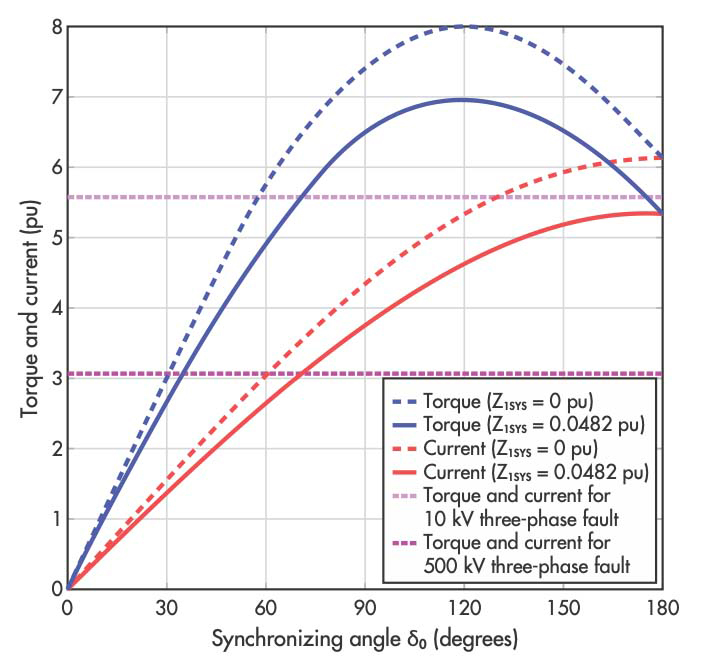
Consider the plot in Figure 7 for a 60-degree OOPS, which plots both current and torque as a function of the synchronizing angle. Five-per-unit torque is applied to the shaft. Therefore, it is pertinent to inspect the machine. The OOPS protection scheme trips the 86 lockout and shuts down the unit. The root cause that led to the OOPS must be determined and properly investigated prior to another attempt to sync the machine.

Steve Turner is in charge of system protection for the Fossil Generation Department at Arizona Public Service Company in Phoenix. Steve worked as a consultant for two years, and held positions at Beckwith Electric Company, GEC Alstom, SEL, and Duke Energy, where he developed the first patent for double-ended fault location on overhead high-voltage transmission lines and was in charge of maintenance standards in the transmission department for protective relaying. Steve has BSEE and MSEE degrees from Virginia Tech University. Steve is an IEEE Senior Member and a member of the IEEE PSRC, and has presented at numerous conferences.