
Properly installed and maintained medium-voltage cable is highly reliable, and when properly installed, there is little or no maintenance to be performed. Yes, you should keep the terminations clean, and yes, you can perform a periodic VLF with tan delta or partial discharge test to trend degradation over the years. However, in my experience, the No. 1 reason cables fail is poor installation practices. Many factors that can impact the quality
of cable installation come into play.
WORKING AROUND DESIGN OF THE GEAR
I still remember one of the first medium-voltage cable faults I cleaned up. It was at a hospital that had recently modified the system to add a new medium-voltage air switch lineup. The installation was in an existing room and required that the conductors enter the switches from the top of the gear. While top-entry gear is nothing new, in this situation, the switchgear as built and delivered to the site was designed to be bottom-fed.
Now, who was to blame for this design issue isn’t relevant to the story, but what happened next was that a well-intentioned electrical contractor found a way around (or should I say through) the switchgear design issue. They decided to route the medium-voltage cables between the switchgear bus to the termination point at the bottom of the switch (see my wonderful sketch in Figure 1).
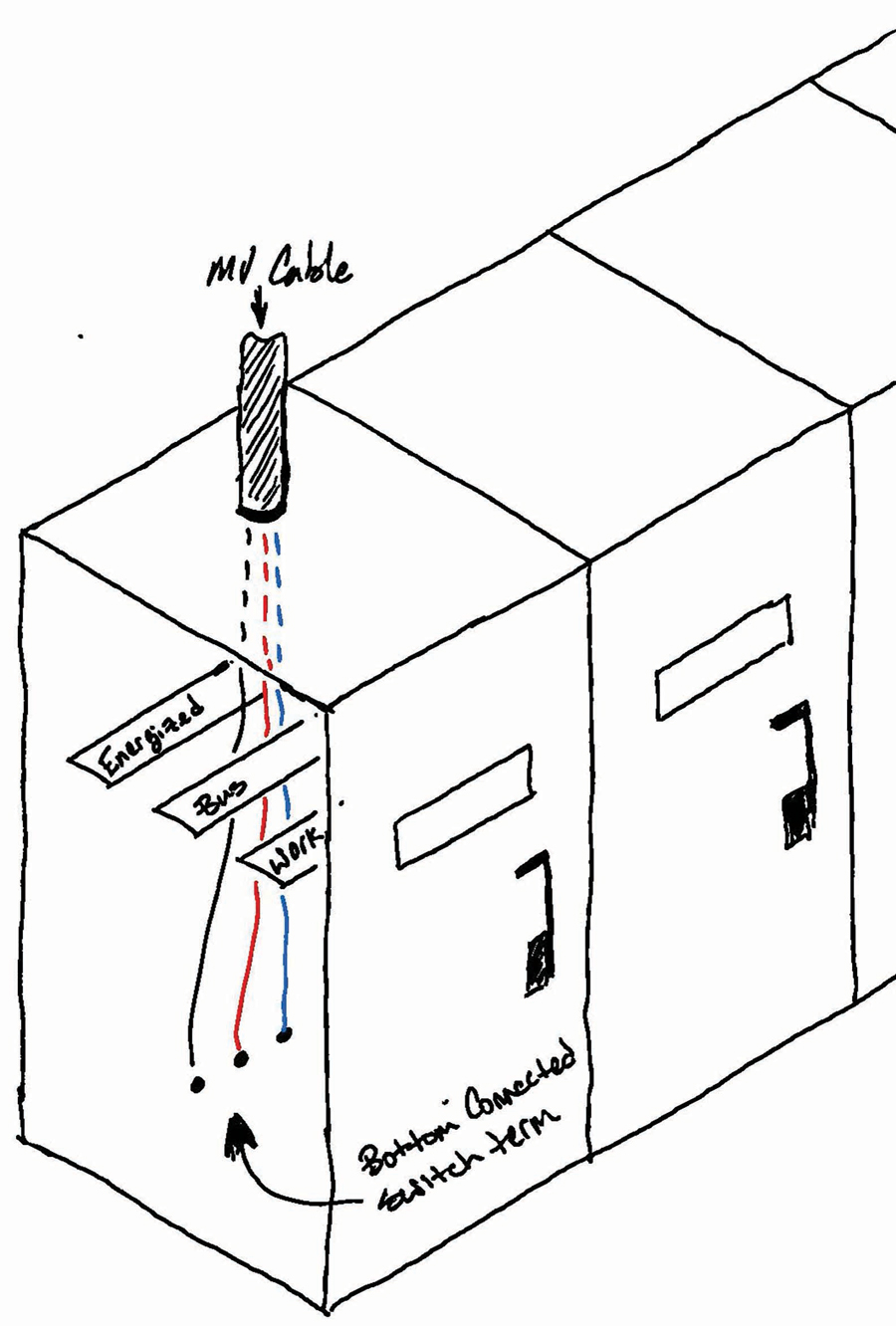
Figure 1: Sketch of Bottom-Fed Switch
The problem with this solution is that it places a grounded plane (the cable’s shield) near the energized bus work. To further illustrate the contractor’s misconception, when I asked why he thought it was acceptable to route the cable in this manner, his response was, “Well, isn’t that insulated cable rated for the voltage?” Where was the NETA testing company in this situation, you might be asking.
A couple of things to consider:
- Technicians commonly show up to test cables and nothing else. If this is the task, their vision of the remainder of the power system might not be in focus. They have a blind spot to other portions of the system.
- Were the cables routed through the bus before or after the test? If they were routed in that manner at the time of testing, then we could argue that the technician should have caught this glaring issue. Of course, that assumes the technician knows enough about cable construction and that he or she notifies the contractor of the issue and stands firm against energizing the system.
- Finally, there is the all-too-human factor of “doing the best we can to make it work.” It’s well-intentioned, tragically flawed, and easier than suffering the consequences of stopping the job to find a better solution — at least until the cable causes a switchgear failure.
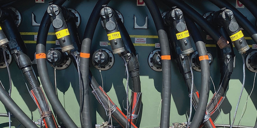
Another equipment design issue that can create challenges in making proper terminations is pad-mounted equipment that limits the distance between the concrete floor and the connection point. This leads to a choice of working in an uncomfortable, hunched-over body position or pulling the cable outside the enclosure where additional length (slack) then must be routed and wrapped back into the gear. This creates problems with bend radius and ensuring that the slack remains clear of energized components as noted in the previous example.
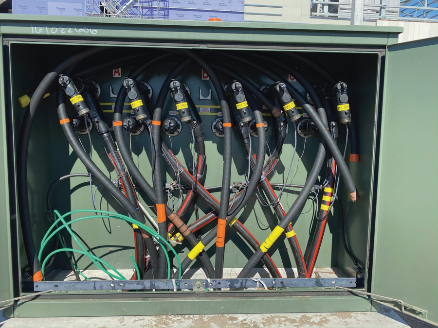
Figure 2: Metering Cabinet
The pad-mounted utility metering cabinet in Figure 2 is an example of a challenging situation I faced in Florida. While there seemed to be plenty of room to make the cables up, it proved very difficult to route the 750 MCM cable to the various termination points from the conduit entries. Had the designer of the installation been aware of this challenge, a trough could have been built/formed under the switch (Figure 3) allowing more movement and easier sweeps of this very stiff cable.
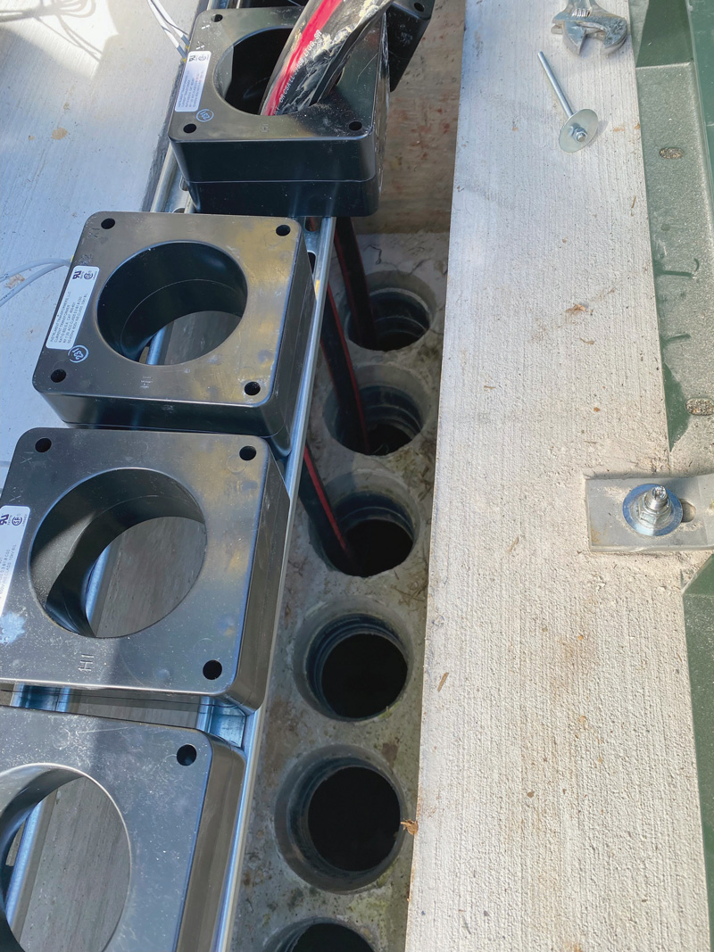
Figure 3: Trough Offering Additional Space to Turn and Route Cables
Figure 4 is another example of a poorly designed plan for how cables would be terminated. Note that there is literally zero room to make the Pfister terminations required on this piece of gear. I wish I knew how this cable was finally terminated, but I left this project long before the cables were completed.
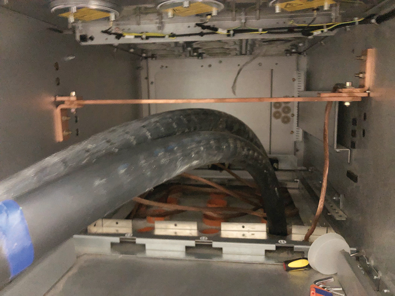
Figure 4: No Room for Terminations
MANAGING EXTRA CABLE LENGTH
There is also the “let’s leave some slack in case I make a mistake in my cable cutbacks” issue. While cable terminators are human and do make mistakes, they should be skilled (if not certified) craftsmen in this specialized talent. This craftmanship extends to being able to plan their work and foresee and manage the challenges in varied installation situations. To be clear, leaving some slack is a fine plan, so long as it doesn’t create issues with managing the extra cable. The pad mount transformer in Figure 5 is a perfect example of extra slack gone horribly wrong.
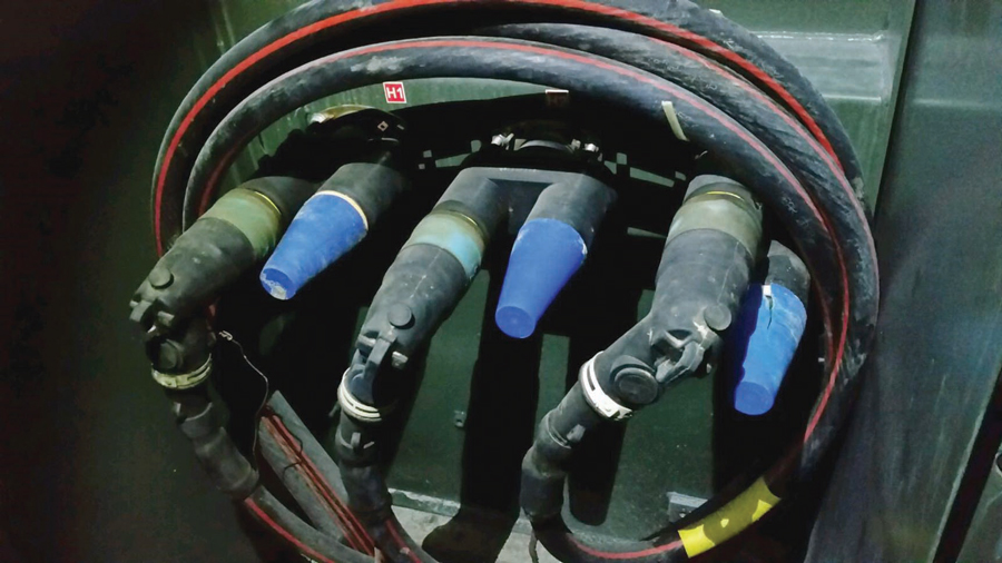
Figure 5: Excessive Slack
INSTALLATION PRACTICES
One of the worst installations I’ve even seen was at a chemical plant that was adding additional capacity. Our team was hired by the electrical contractor to test the new cable installations. Our initial test of the cables indicated a termination issue. The issue was sufficiently bad to trip the VLF test set before getting to the withstand voltage. This was followed by an uncomfortable conversation with the contractor that they were going to need to pull new cable to correct the issue.
As with any failed cable test, the first thing to check is the cutbacks of the cable made during the process of installing terminations. Removing terminations costs money and time, and if you are wrong, you can expect you will be asked to pay for those losses. In this case, we were not wrong. Figure 6 clearly shows the poor installation made by an inexperienced and rushed electrician.
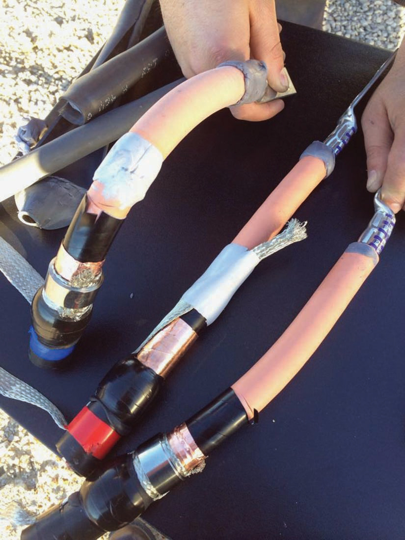
Figure 6: Exceptionally Poor Cutbacks
Note that this photo was taken after surgically removing the terminations to avoid any alteration of what we discovered. The defects were numerous and included:
- Poor cutbacks
- Deep cuts into the cable installation at the semi-con cutback
- Failure to install the constant tension spring, which allowed the braided shield to be pulled out of place toward the cable lug when the core was removed from the stress cone
Admittedly, it is rare to find a cable this poorly constructed, but I assure you that it can and does happen.
WATER INTRUSION IN THE CONDUCTOR
Another rare installation issue technicians need to be aware of involves outdoor terminations, which are typically connected to pole-mounted cutout switches with mechanical lugs. An inexperienced terminator who is not provided with all the proper materials may leave bare conductors exposed for installation into the lug (Figure 7). On the surface, you may not see an issue with this practice, but consider that this outdoor installation is exposed to rain. Over the course of time, rain will migrate into the cable conductor.
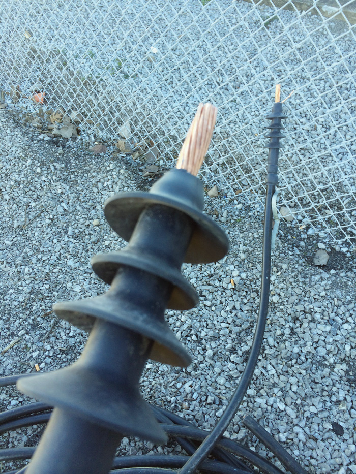
Figure 7: Cable Allowing Water Intrusion
The water will build up and create a water column going up the pole, and this water column is capable of building up enough pressure to push loadbreak elbows off their bushings at the pad-mounted equipment that is often located at the other end.
Another situation I encountered was on a deadbreak connection. A similar bare conductor installation at the pole pushed water into the deadbreak. When the water froze, it expanded the deadbreak to the point that it failed catastrophically.
ADDING NEW CABLES TO AN EXISTING INSTALLATION
In a recent situation, new cables were added to connect an existing switch to a new switch being installed in an expansion. The old termination required a longer cutback to the cable shield than the new termination. On the surface, it didn’t seem like a big issue. However, this mismatch of the ground shield (Figure 8) placed a grounded point adjacent to the unshielded portion of the existing cable.
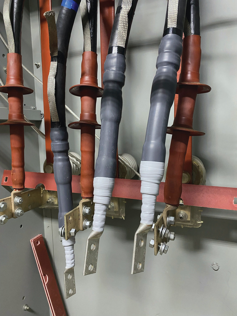
Figure 8: Mismatched Ground Shields
Over time, the ground shield on the new cables will create electrical stresses that could eventually cause a failure of the existing cable. The solution to this issue is to modify the new cable cutbacks so that the shield grounds are at the same position (red arrow). The additional exposed insulation this change creates in the new cable can then be wrapped with silicon splicing tape (blue arrow) to complete the moisture barrier at the end of the cable.
CONCLUSION
If you want to create reliable medium-voltage cable systems, learn from these life lessons:
- Never allow medium-voltage cable to be adjacent to energized components.
- Avoid excessive slack in cable systems.
- Plan ahead for cable sweep and bend radius management.
- Trust your test equipment.
- Properly install terminations in accordance with the manufacturer’s instructions.
And as Dad always said, “Keep it clean, read the instructions, measure twice, and keep it clean.”
 Mose Ramieh is Vice President, Business Development at CBS Field Services. A former Navy man, Texas Longhorn, Vlogger, CrossFit enthusiast, and slow-cigar-smoking champion, Mose has been in the electrical testing industry for 24 years. He is a Level IV NETA Technician with an eye for simplicity and utilizing the KISS principle in the execution of acceptance and maintenance testing. Over the years, he has held positions at four companies ranging from field service technician, operations, sales, business development, and company owner. To this day, he claims he is on call 24/7/365 to assist anyone with an electrical challenge. That includes you, so be sure to connect with him on the socials.