

Relay testing has long been one of the more technically demanding and complicated aspects of the business of electrical acceptance and maintenance testing. The plethora of skills required to be an excellent relay technician includes (in no particular order) electrical theory, power system design, AC and DC control drawing interpretation, and the ability to simulate power system faults to name a few. The progression from testing electromechanical relays with a single-phase SR-90 relay test set to the proliferation of microprocessor relays to computer-driven test sets underscores the dramatic changes in the field.
With all the changes in relay technology, a few things haven’t changed. The people who design, build, engineer, install, program, and test them are all fallible human beings who make mistakes. A 2021 report from the Western Electricity Coordinating Council (a region that reports to NERC) documented that as much as 45% of relay misoperations (Figure 1) can be attributed to the personnel who are responsible for ensuring that the relay system operates properly. My own anecdotal experience is that relays generally operate correctly (representing only 13% of failures in the 2021 WECC Report). Issues with wiring installation, design/logic, and testing practices are more common.
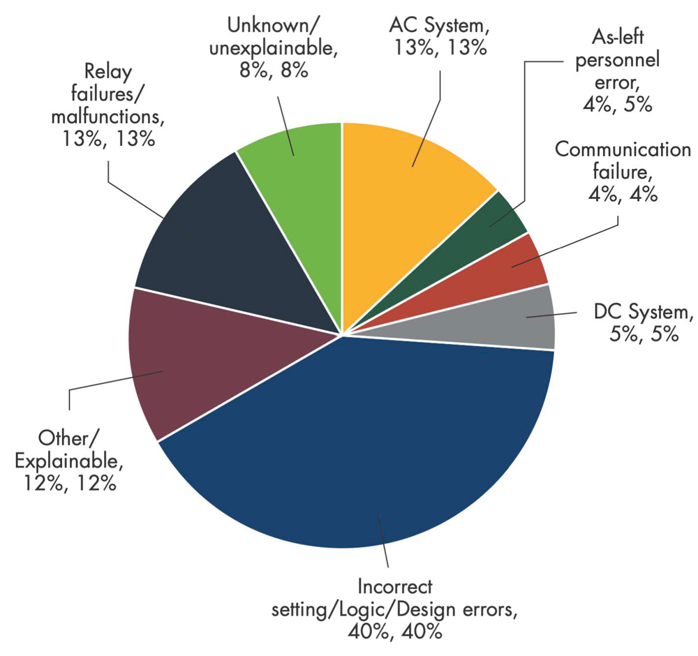
Image Courtesy Western Electricity Coordinating Council (WECC) Relay Work Group
I anticipate that several articles in this issue of NETA World will talk about the advances in relay protection and the best practices for testing them. While this is valuable information, I will focus on the seemingly simple but most prevalent problems for technicians in the field and share a few hard-learned laws of electrical testing developed from the bad experiences I have endured.
CHECK FOR WIRING ISSUES
One challenging situation involved an SEL 351S relay’s reclosing function. This substation’s four feeder breakers were being acceptance tested. After completing metering, inputs/outputs, and protective relay functions, I attempted to verify the reclosing feature. I was very proud of the event sequencer I had written expecting everything to go well and was disappointed when the plan failed to achieve the expected outcome.
I spent time attempting to identify what I was doing wrong. After checking and rechecking my test plan, the test continued to fail. I even went so far as to share my challenge with some trusted resources in hopes of uncovering the issue but to no avail. The troubleshooting was complicated because the test failed on different shots — it wasn’t always the same shot in my test plan. After an entire day of this troubleshooting, I received some simple and profound advice: Move on to the next relay.
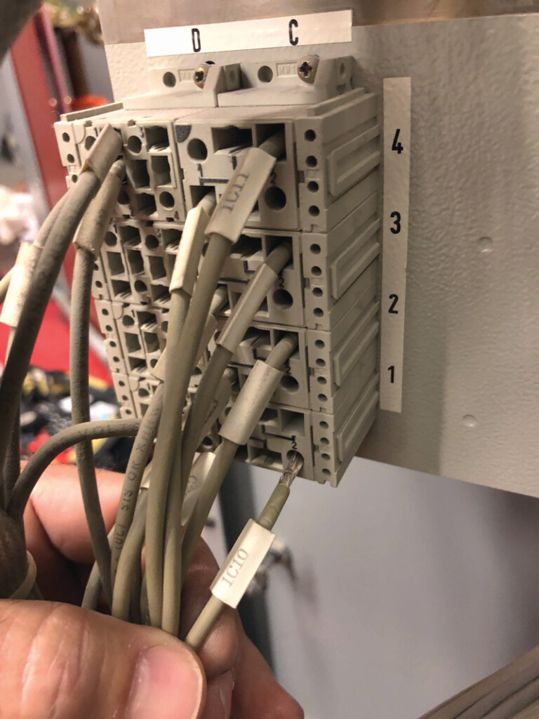
To my amazement, the next breaker and relay worked perfectly, and so did the next two. This was a valuable and hard-learned lesson and is a good law of electrical testing regardless of the apparatus you are working on. We get wrapped up in trying to determine what we are doing wrong, and we fail to conceive that there could be an equipment or wiring issue. I would later discover, after a great deal of time, that there was a loose wiring connection in the close command circuit to the breaker. This loose connection (Figure 2) caused the breaker to unpredictably fail to close when commanded by the relay, which would then cause my test plan to fail as it required the breaker to go closed for the next shot test.
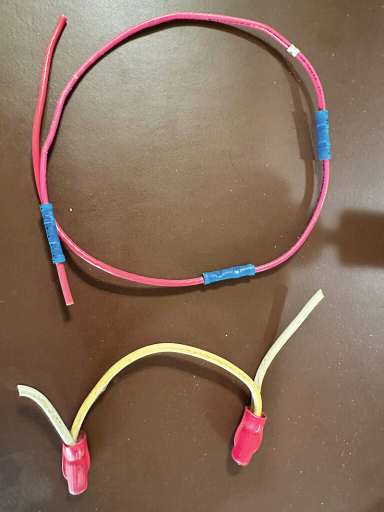
While some issues are challenging to identify, others are simply created by well-intentioned individuals who didn’t follow best practices. Our company was hired to clean up the control system of a relocated and modified standby generator system. During this process, I removed hundreds of feet of abandoned control wiring and found numerous issues. My souvenir box still contains a section of wire roughly 12 inches long with three butt splices and wire nuts (Figure 3). I can’t be entirely sure, but I suspect the person installing the circuits was unsure where to land the wire and had to add wire to make it long enough to get to its final and correct location. Removing the butt splices and wire nuts and using proper wiring practices, I corrected this issue by using spare terminal block points and making a jumper to complete the circuit. Law of electrical testing: Butt splices and wire nuts have no place in power system control circuits.
ELECTRICAL APPARATUS ARE NOT TABLES
While not exactly a wiring issue, there was once a tricky situation with a relay system that was exhibiting unexpected operations during start-up testing. Anyone who has wired a relay in the field knows that the relay is a tempting place to set tools and other items like screws and ring terminals. It takes discipline to remember that electrical apparatus such as breakers, transformers, relays, etc., are not to be used as a table. The unexpected relay operations were the direct result of several uninsulated ring terminals sliding off a relay being used as a table and onto the terminal strip of the relay and behind the relay wiring (Figure 4) with the ring terminal landing on top of the relay terminal strip. This was a difficult find as the relay wiring did a wonderful job of hiding the ring terminals. Once the ring terminals were found and removed, the spurious and unexpected operations ceased to exist.
SETTING ERRORS
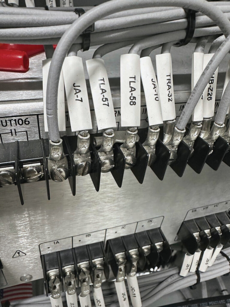
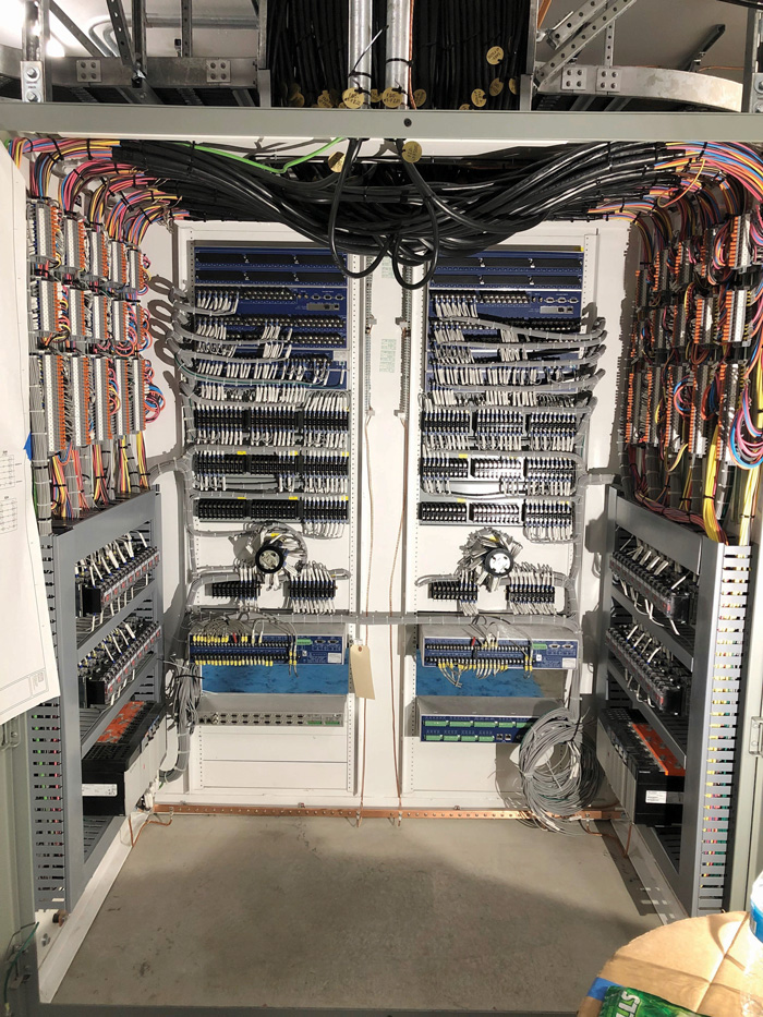
One could write a book on this topic, and it’s particularly true as relay settings and protective schemes become increasingly more complicated (Figure 5). With hundreds if not thousands of connections, what could possibly go wrong? This can lead to a variety of unintended and difficult-to-simulate situations that effectively test the entire protective architecture across a geographically diverse power system.
Keeping it simple, let’s look at one example of human error that is introduced anytime settings are changed for testing. It has been routine for relay technicians to modify protective settings (turning features on or off) to enable them to verify independent protective elements more easily. This is a carryover from the processes used to test electromechanical relays where each device serves a discrete function and testing one doesn’t interfere with the others. While it might seem to take longer to set up, a test plan simulating real-world power system faults is more effective at identifying issues, and it eliminates the possibility of leaving a setting disabled at the end of the test.
A baffling example of settings and human error was recently brought to light at a solar installation. After protective system commissioning, a site representative would disable the relay(s) protection to allow for the abnormal energization of the power system from the utility source to soak their transformer(s). Left in service, the relay(s) would see the transformer in-rush as a fault and open the breakers. The problem was that the individual who defeated the relay(s) was not on site to re-enable the relay(s) once the system was put into normal service. This left the site without proper relay protection and vulnerable to catastrophic faults.
To mitigate this issue and still enable initial system energization, our team suggested that a second group of settings be utilized for the initial in-rush ride-through and then immediately be reverted to the proper coordinated settings for normal service. This process affords protection during initial energization and reduces the human error risk of not re-enabling the proper settings.
MAINTENANCE TESTING AND SYSTEM VERIFICATION
When it comes to maintenance testing of relay systems, a holistic approach is best. It is often difficult to convince customers of the value of operating the protective system. So much of the relay maintenance testing I have seen focuses on the protective relay. While electromechanical relays should be tested for proper protective function following the periodicity requirements in NFPA 70B, microprocessor relays don’t require the same scrutiny if appropriate start-up testing is done.
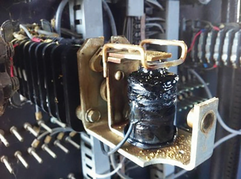
Regardless of the relay type, the operational aspects of the system should be periodically checked and verified. These checks, however, can be incompatible with the customer’s desire not to de-energize the entire power system. Take the example of verifying the relay that operates an 86-lockout relay. The lockout relay generally is used to allow one relay to trip multiple breakers. This is an extremely important device in the protective system, but it can and does fail. This failure is typically created when a system operator doesn’t understand how to reset them properly. Figure 6 shows the failed coil of an 86 relay that was found after a catastrophic fault in a 15 KV switchboard that was not cleared by the protective relays.
Relay Failures
Sometimes, the problem is the relay. It is uncommon, only accounting for roughly 13% of failures as noted above, but today’s modern relay can have issues, as a technician found while testing an SEL 751 with a sync check.
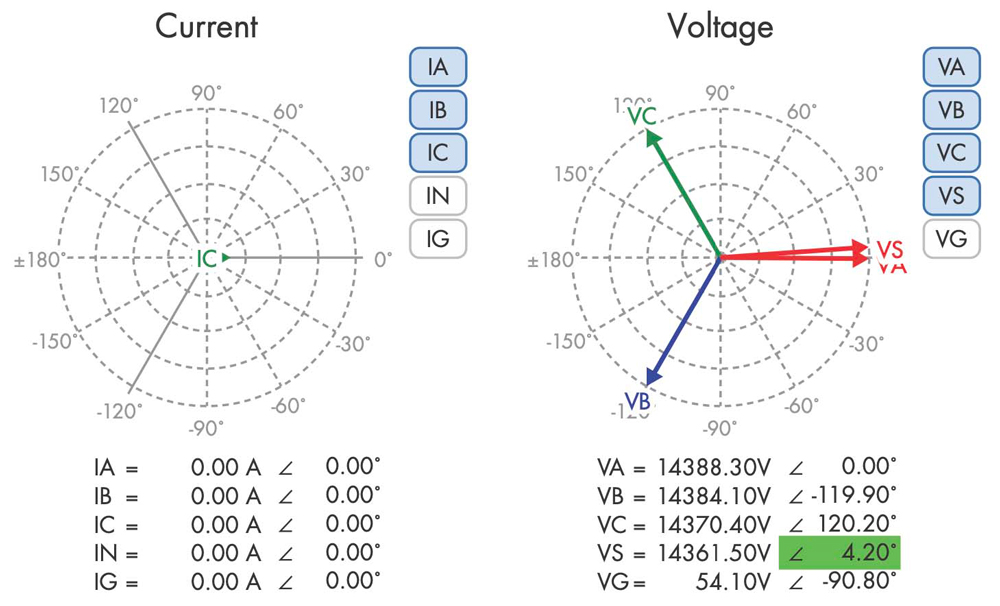
With voltage applied to the bus voltage and sync voltage input of the relay, the technician varied the sync voltage angle to determine the point where the programmed output would close. The expected angle difference was 10 degrees, but the actual value was 4.2 degrees shifted in the positive direction. After double-checking everything and a few repeated attempts, the technician documented the findings and moved on to the next relay. The next one exhibited the same disparity, as did two others. This issue persisted with 4.2 degrees shifted even with the voltage sync (VS) and voltage A bus (VA) channels connected directly to each other (Figure 7), effectively eliminating the test set as a source of the error.
Utilizing the available resources, the technician called the manufacturer. It took some digging for the factory to find the answer. It turns out the relays were shipped from the factory without the card for the sync voltage input. These cards were ordered and installed later by the company building the switchgear package. This meant the two voltage cards had not been calibrated as a unit at the factory, leading to the 4-degree difference between the two voltage systems. The calibration settings are internal on the card and are preset by the manufacturer, and the settings did not load properly to the relay when the cards were installed. The reason was still unknown by the manufacturer, but they provided a procedure that allowed for factory calibration in the field. This corrected the issue and was followed up by a verification retest of the sync check element.
Misoperation and Other Explainable Failures
I must include a discussion about transformer differential relays. Electromechanical relays determined whether your current inputs were correct, and measuring operating current required the use of a current thief, multimeters, and phase angle meters. Today, it is much simpler to obtain these values by connecting a computer or simply scrolling the values on the front face of the relay.
To illustrate the challenges, a client replaced a breaker in their substation. This involved having to connect existing differential current transformer wiring to the new breaker’s current transformers. Understanding that this could present a wiring error, we were to measure the differential circuit for current angle, magnitude, and operating current before returning the differentia system to service. Even though the measurements indicated there was a problem, the decision was made that it was “close enough,” and the relay was placed in service. It didn’t take long before the load was high enough to operate the relay and shut down the whole substation — and the customers it served. Learning about this situation, I was perplexed that those smart individuals made a poor decision. With the additional attention this misoperation brought with it, the wiring mistake was identified and corrected.
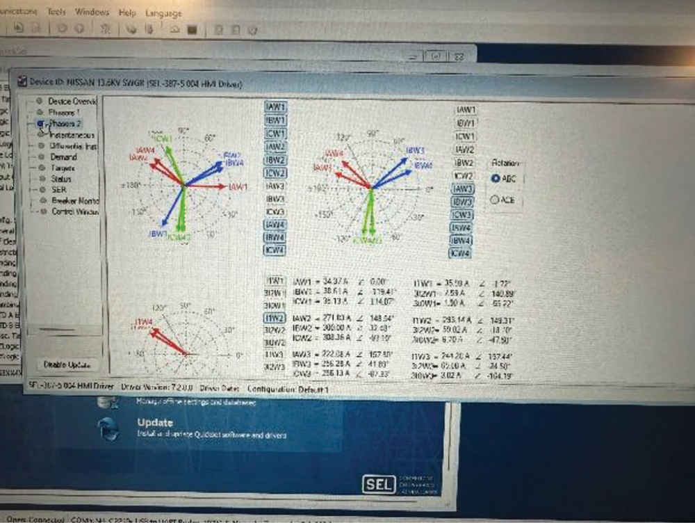
Fast forward to our modern relays. Even with the benefit of live phasor views (Figure 8) and the ease of viewing and measuring operating and restraint current, mistakes occur.
More than once, a new system has been energized, but these critical measurements were not made or the warning signs were missed or ignored. Upon energizing one substation, it was noted that there was 0.1 amps of operating current. The technician called it “good” and left, only to get a call a few hours later that the substation had tripped on differential. That is, of course, one of the funny things about differential relays: Until the load gets up, generally around 30%, they aren’t going to trip. This leads to a false sense that everything is correct.
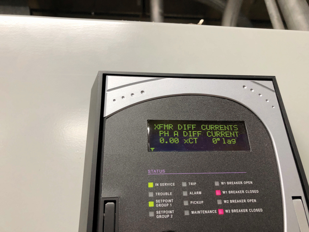
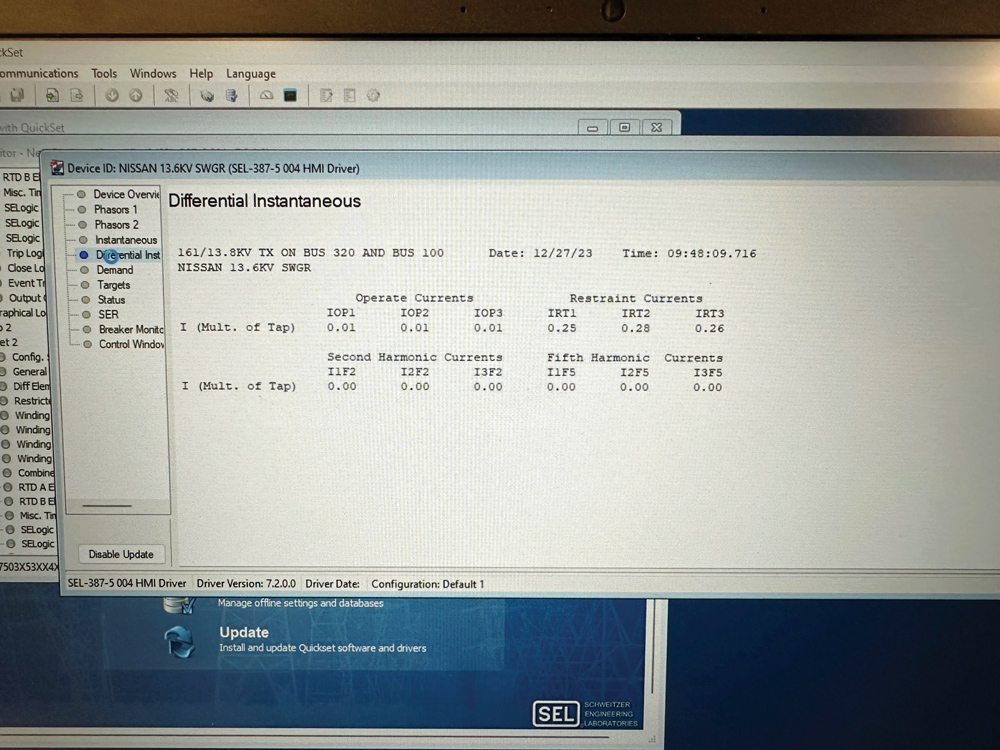
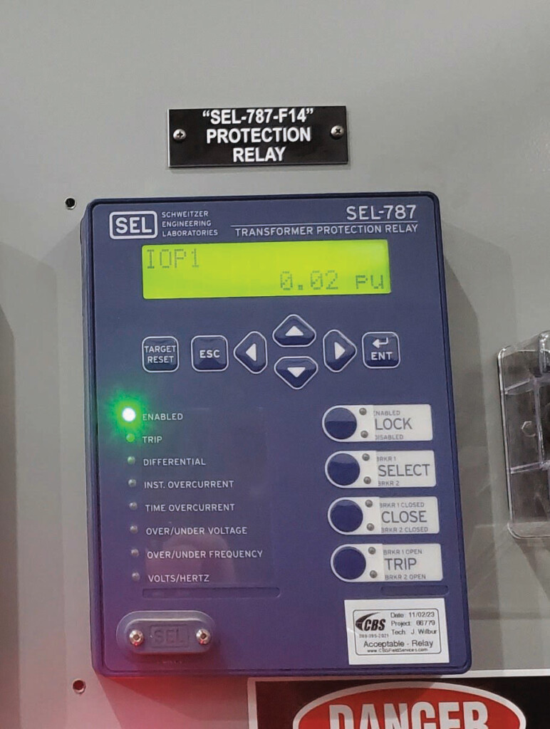
It was following this event that I created another one of my laws of electrical testing: The only acceptable operating current is 0.0 amps. Not 0.1! If it’s not 0.0, something is wrong and must be corrected before putting the relay in service. Figure 9, Figure 10, and Figure 11 are examples of 0.0 operating current documentation.
CONCLUSION
Those responsible for verifying the proper operation of protective relays have a special and vital role in the power system. Any mistakes made in design, installation, or testing can lead to catastrophic failures, potentially allowing equipment damage, personnel injury, or at the very least, unintended outages and the inconvenience that a loss of electrical service creates. Applying and adhering to acceptance and maintenance testing processes and procedures can produce a more reliable and safe power system. Next time you think something is good enough or you normalize a deviation from the expected, remember that people are depending on you.
REFERENCES
Western Electricity Coordinating Council Relay Work Group. 2021 Misoperation Report, September 2022. Accessed at https://www.wecc.org/Administrative/RWG 2021 Misoperation Report.pdf.

Mose Ramieh is Vice President of Business Development at CBS Field Services. A former Navy man, Texas Longhorn, Vlogger, CrossFit enthusiast, and slow-cigar-smoking champion, Mose has been in the electrical testing industry for more than 25 years. He is a Level IV NETA Technician with an eye for simplicity and utilizing the KISS principle in the execution of acceptance and maintenance testing. Over the years, he has held positions at four companies ranging from field service technician, operations, sales, business development, and company owner. To this day, he claims he is on call 24/7/365 to assist anyone with an electrical challenge. That includes you, so be sure to connect with him on the socials.