

At 5:45 AM on a particularly cold winter day, an industrial manufacturing plant experienced a significant electrical fault event on a 15kV substation that feeds power to approximately 30% of the manufacturing operations.
FAULT ON FEEDER M1A: WHAT HAPPENED?
The main circuit breaker in one of the plant’s three medium-voltage substations experienced a fault, arc flash event, and subsequent trip of the entire lineup, apparently due to a rodent that caused a phase-to-phase fault in the 15kV potential transformer (PT) compartment. The fault traveled into the medium-voltage bus assembly in the metal-clad switchgear lineup, ultimately causing the main breaker to trip and de-energizing a large portion of the facility.
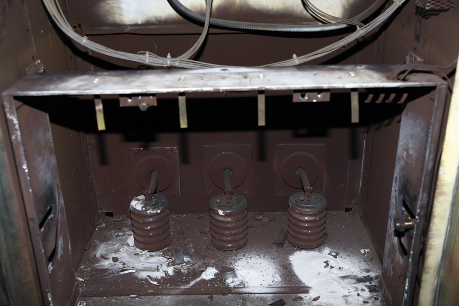
Faulted PT Compartment
THE LIGHTS ARE OUT: NOW WHAT?
For the electrical worker in the field, this all too common: A significant medium-voltage electrical fault event occurs, production lines are down, people are standing around, and management needs the facility back up and running as soon as possible. Time. Is. Money.
For a qualified electrical worker, especially when it involves medium-voltage equipment and systems, many aspects of NFPA 70E immediately kick into action. The intent of this article is to highlight a few real-life 70E scenarios for the worker in the field.
APPLYING NFPA 70E TO A MEDIUM-VOLTAGE FAULT EVENT
Scene No. 1: What’s the Risk?
What’s the first thing you do? Make sure it’s de-energized? Or is it more than that? The answer can be found in Key Point: Article 110 General Requirements for Electrical Safety-Related Work Practices. You need to assess the risk before any work begins.
The substation is dark, the sun is coming up, and the smoke is just starting to clear. There is general chaos around the substation: damaged equipment, loss of power, emergency systems are running. Effects from the outage are felt throughout the plant, and members of upper management are starting to arrive to “lend a hand”….and you just arrived on the scene as the person in charge of the remediation. Remain calm. Assess the risk. Map out the plan and recovery strategy in your mind and apply the rules and requirements of NFPA 70E in your thought streams.
Key Point: Article 110.1 Priority
Hazard elimination shall be the first priority in the implementation of safety-related work practices.
NFPA 70E is very clear on this point. It’s at the front of the standard, and the intent is for you to plan all of your tasks and protect all of the employees working on or near the electrical equipment. OSHA 29 CFR 1910.333(a)(1) also states:
Live parts must be de-energized before the employee works on or near them.
To assess the risk, you must apply several principles of safe work practices before you begin, including:
1. Identifying the hazards and minimizing the risks
2. Establishing an electrically-safe work condition
3. Protecting employees, including workers on the project and other bystanders
4. Planning all the tasks to be performed
5. Anticipating unexpected events and developing a plan to deal with them
6. Confirming the qualifications and abilities of anyone working on the project
7. Determining the condition of maintenance of the electrical equipment
8. Using the correct tools and appropriately rated portable meters
It’s clear that a risk assessment must be performed before troubleshooting and repairs begin.
Key Point: Article 110.5(H)(1) Elements of a Risk Assessment Procedure
The risk assessment procedure shall address employee exposure to electrical hazards and shall identify the process to be used before work is started to carry out the following:
(1) Identify hazards
(2) Assess risks
(3) Implement risk control according to the hierarchy of risk control methods
So if you follow 110.5(H)(1) you should: Identify the hazards, analyze the risk, and also evaluate the risk.
Remember, risk is not only the likelihood that an incident might occur, but also the possible severity of injury or [further] damage to equipment that could result from an incident. So the risk might have a high probability of occurrence, but the result could be a minor injury. Or conversely, the incident might have a low likelihood of occurrence but present the possibility of severe injury. You have to consider what your scenario will likely bring about.
For example: Are there high levels of risk, including shock and arc flash hazards? Or does shock hazard create the greatest risk, with a minimal risk from incident energy exposure?
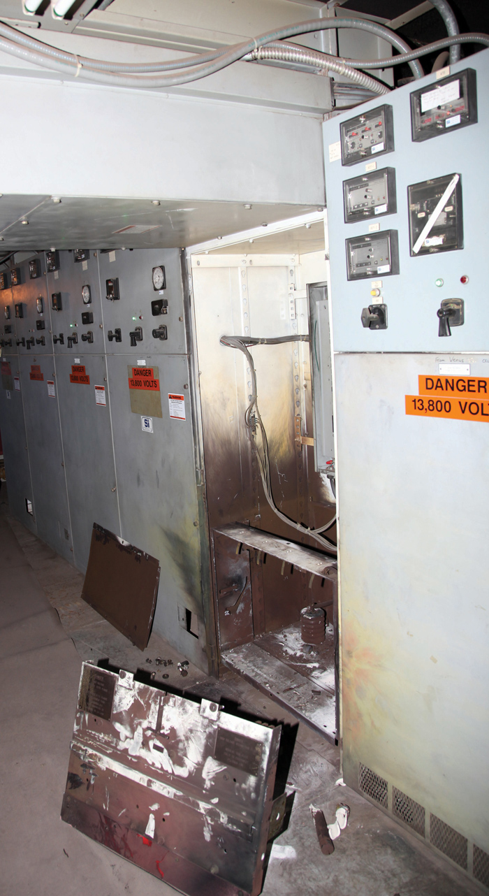
Faulted Enclosure
Key Point: NFPA 70E Annex F Risk Assessment and Risk Control
For further information and guidance on risk assessment, please refer to Annex F in the 70E.
Scene No. 2: Energized, De-Energized, or Electrically Safe?
We know power is out to the substation. After all, the rodent caused a large arc flash and fault event, and everything is shut down. The alarms tell us that, the noise — or lack of noise — tells us that, and the burned rat laying in the substation tells us that. And upper management has already reminded us several times and asked, “The power is out, and what are you going to do about it?”
But de-energization itself does not create an electrically safe work condition (ESWC), and just because something is de-energized does not describe a safe condition. Remember those emergency alarms and annoying sirens? Where is that power coming from?
What you must do, before any work begins, is establish an electrically safe work condition.
The main premise for providing employees an electrically safe work environment is to place electrical equipment in an electrically safe work condition unless it is being used under normal operation.
Key Point: Article 120.5 Process for Establishing and Verifying an Electrically Safe Work Condition
Any time a piece of equipment has been de-energized and service or maintenance work is to be performed, follow the very specific process in 120.5 of the 70E to establish the ESWC:
Establishing and verifying an electrically safe work condition shall include all of the following steps, which shall be performed in the order presented (emphasis added), if feasible:
1. Determine all possible sources of electrical supply to the specific equipment. Check
applicable up-to-date drawings, diagrams, and identification tags.
2. After properly interrupting the load current, open the disconnecting device(s) for each source.
3. Wherever possible, visually verify that all blades of the disconnecting devices are fully open or that drawout-type circuit breakers are withdrawn to the test or fully disconnected position.
4. Release stored electrical energy.
5. Block or relieve stored nonelectrical energy in devices to the extent the circuit parts cannot be unintentionally energized by such devices.
6. Apply lockout/tagout devices in accordance with a documented and established procedure.
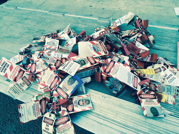
Lockbox for Lockout Devices
7. Use an adequately rated portable test instrument to test each phase conductor or circuit part to test for the absence of voltage. Test each phase conductor or circuit part both phase-to-phase and phase-to-ground. Before and after each test, determine that the test instrument is operating satisfactorily through verification on any known voltage source.
8. Where the possibility of induced voltages or stored electrical energy exists, ground all circuit conductors and circuit parts before touching them. Where it could be reasonably anticipated that the conductors or circuit parts being de-energized could contact other exposed energized conductors or circuit parts, apply temporary protective grounding equipment in accordance with the following:
a. Placement. Temporary protective grounding equipment shall be placed at such locations and arranged in such a manner as to prevent each employee from being exposed to a shock hazard (i.e., hazardous differences in electrical potential). The location, sizing, and application of temporary protective grounding equipment shall be identified as part of the employer’s job planning.
b. Capacity. Temporary protective grounding equipment shall be capable of conducting the maximum fault current that could flow at the point of grounding for the time necessary to clear the fault.
As you can see, NFPA 70E provides a great resource for the process to establish an ESWC. Use it to execute your strategy to prepare the worksite for the remediation efforts on the 15kV switchgear.
We have now completed two of the eight steps we originally mapped out in our emergency project by specifically following the guidance presented to us in NFPA 70E. Those original steps were:
1. Identifying the hazards and minimizing the risks (done)
2. Establishing an electrically-safe work condition (done)
3. Protecting employees, including workers on the project and other bystanders
4. Planning all the tasks to be performed
5. Anticipating unexpected events and have a plan to deal with them
6. Ensuring qualifications and abilities of anyone working on the project
7. Determine the condition of maintenance of electrical equipment
8. Using correct tools and appropriately rated portable meters
Stayed tuned for future issues of NETA World as we go through the balance of these steps to get the facility back up and running.
As for the culprit to all of this, Mickey the mouse? He, unfortunately, is not doing too well. Electricity is a dangerous thing, man.
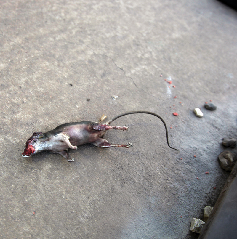
Oh, Mickey — You Did it Now
Stay safe out there, turn it off, and Test Before Touch!
Ron Widup and Jim White are NETA’s representatives to NFPA Technical Committee 70E, Electrical Safety Requirements for Employee Workplaces. Both gentlemen are employed by Shermco Industries in Dallas, Texas, a NETA Accredited Company.
 Ron Widup is the Vice Chairman, Board of Directors, and Senior Advisor, Technical Services for Shermco Industries and has been with Shermco since 1983. He is a member of the NETA Board of Directors and Standards Review Council; a member of the Technical Committee on NFPA Standard for Electrical Safety in the Workplace (NFPA 70E); Principal member of the National Electrical Code (NFPA 70) Code Panel 11; Principal member and Chairman of the Technical Committee on Standard for Competency of Third-Party Evaluation Bodies (NFPA 790); Principal member and Chairman of the Technical Committee on Recommended Practice and Procedures for Unlabeled Electrical Equipment Evaluation (NFPA 791); a member of the Technical Committee Recommended Practice for Electrical Equipment Maintenance (NFPA 70B); and Vice Chair for IEEE Std. 3007.3, Recommended Practice for Electrical Safety in Industrial and Commercial Power Systems. He is a member of the Texas State Technical College System (TSTC) Board of Regents, a NETA Certified Level 4 Senior Test Technician, State of Texas Journeyman Electrician, a member of the IEEE Standards Association, an Inspector Member of the International Association of Electrical Inspectors, and an NFPA Certified Electrical Safety Compliance Professional (CESCP).
 James (Jim) R. White, Vice President of Training Services, has worked for Shermco Industries since 2001. He is a NFPA Certified Electrical Safety Compliance Professional and a NETA Level 4 Senior Technician. Jim is NETA’s principal member on NFPA Technical Committee NFPA 70E®, Electrical Safety in the Workplace; NETA’s principal representative on National Electrical Code® Code-Making Panel (CMP) 13; and represents NETA on ASTM International Technical Committee F18, Electrical Protective Equipment for Workers. Jim is Shermco Industries’ principal member on NFPA Technical Committee for NFPA 70B, Recommended Practice for Electrical Equipment Maintenance and represents AWEA on the ANSI/ISEA Standard 203, Secondary Single-Use Flame Resistant Protective Clothing for Use Over Primary Flame Resistant Protective Clothing. An IEEE Senior Member, Jim was Chairman of the IEEE Electrical Safety Workshop in 2008 and is currently Vice Chair for the IEEE IAS/PCIC Safety Subcommittee.