
Megohm or insulation resistance tests validate the insulating properties of electrical conductors. A conductor with good insulation will have high insulation resistance — often measured in giga-ohms (GΩ). A conductor with bad insulation will have lower insulation resistance, which can create a pathway for excessive leakage current.
No insulation is perfect, but the goal of the test is to quantify the insulation’s resistance value to better understand the conductor’s health. In this article, we will use a PV string example to explain how the test process works and what steps to follow when performing the test in the field.
WHAT IS AN INSULATION RESISTANCE TEST?
Insulation resistance testing is a non-destructive test procedure that measures the insulation resistance between a conductor and ground. The PV industry commonly uses the test before energizing cables during project commissioning and regularly scheduled maintenance and as a tool for diagnosing system performance issues, especially earth/ground faults.
Performing an insulation resistance test can apply a higher-than-usual voltage to a conductor.
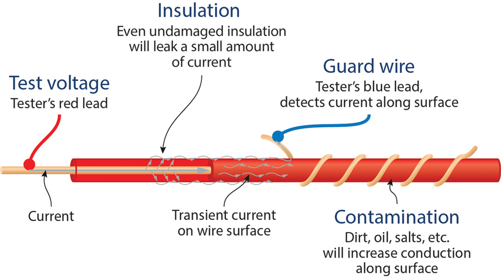
The test instrument will apply a voltage to the conductor during the test. If the insulation is compromised, the applied voltage will cause some current to leak, and the instrument will use Ohm’s law to determine the insulation’s resistance (Figure 1 and Figure 2).
When running an insulation resistance test on a compromised conductor, additional current will leak out, and the test instrument will record a low resistance value. International Electrotechnical Commission (IEC) standards for insulation resistance testing state:
PV systems with an open circuit voltage rating greater than 120 V DC must have an insulation resistance greater than 1 MΩ.
HOW ARE INSULATION RESISTANCE TESTS PERFORMED?
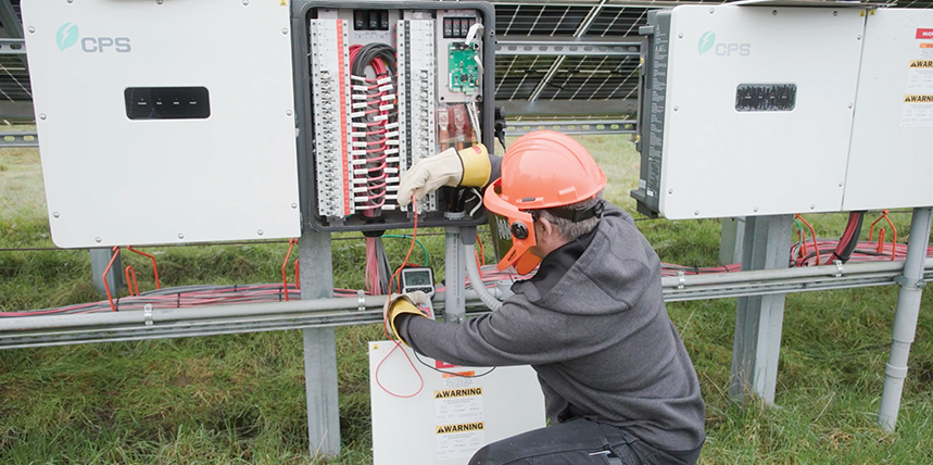
Insulation resistance tests place a high voltage on the components under test. Technicians must maintain a safe working environment for themselves and others working on the electrical system, starting by isolating all power electronics and surge protection devices from the circuit under test. Failure to do so can result in damage to the components. Technicians who wish to perform insulation resistance tests through a PV module must obtain approval from the module manufacturer. To avoid damage, the test voltages applied should remain less than or equal to the PV module’s maximum voltage rating. IEC 62446 Table 2 provides minimum test voltages and insulation resistance values.
Before performing tests, the working area must be appropriately identified and isolated. All technicians on-site must be notified of the tests so they do not inadvertently come in contact with any components under test. Technicians must also wear proper personal protective equipment (PPE). At a minimum, high-voltage gloves and safety glasses must be worn when performing tests.
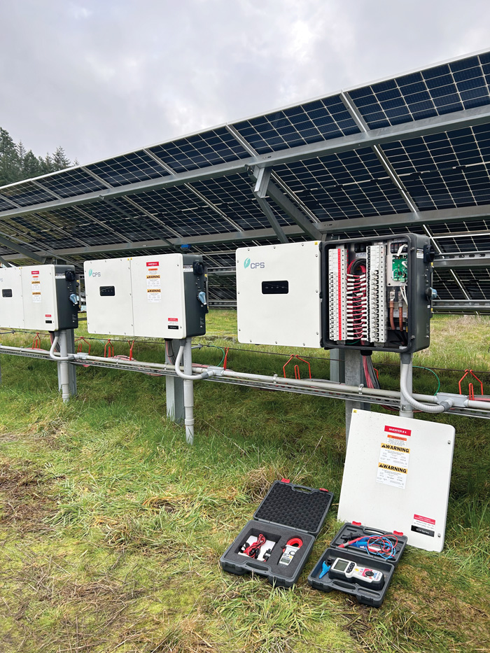
The circuit under test should be fully isolated with disconnect(s) in the OFF position. Technicians should verify that expected voltage and current values are present within the circuit. Current should be zero in each conductor, voltage from each positive and negative terminal to the ground bar should be zero, and voltage from each positive terminal to each negative terminal should be roughly equal to the module VOC if the sun is shining. Now it’s time to pull out the insulation resistance tester. The test setup will vary depending on which circuit is being tested.
Testing through PV String Conductor
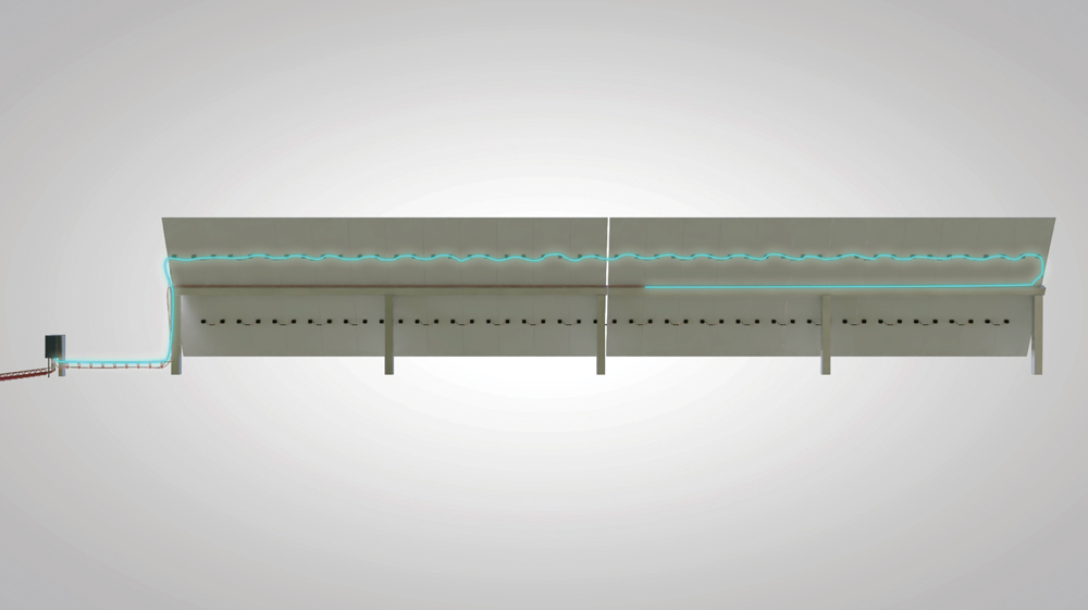
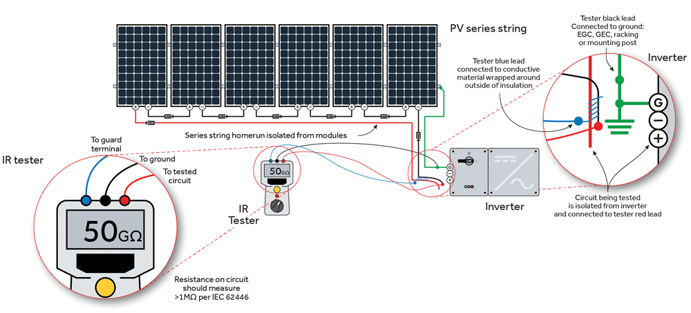
To test through the PV string conductor, attach the tester’s red lead to the negative homerun termination point for that string and the black lead to the ground bar inside the inverter or combiner box (Figure 3).

When the test runs, DC voltage will be applied across the entire string. Note that the result displayed on the test instrument is 50 kΩ. This is below the 1-MΩ threshold set by the IEC and indicates that one or more of the conductors in the string could be damaged. Let’s attach the guard wire and retest to see if surface leakage is the cause of the low resistance reading.
Testing Using the Guard Circuit
To test using a guard circuit connection (when available),connect the third terminal (guard) of the tester to a conductive material (e.g., bare copper wire) wrapped around the conductor’s jacket near the test end of the cable (Figure 4). The guard wire will conduct any surface leakage caused by contamination on the outside of the conductor and bypass this current around the test instrument’s metering circuit.
Surface leakage in this case refers to leakage current due to contaminants — water or debris that could increase conduction on the outer surface of the insulation. It’s also possible for contaminants to work their way into the insulation through a process called electrical treeing, but any absorption into the insulating material is already accounted for by the test instrument.
Since we’re still testing the PV string conductor, the placement of the red and black test leads will remain the same. A third, typically blue, lead is attached to a bare copper wire wrapped near the ends of the positive and negative homerun conductors. Note that the result displayed on the test instrument is now above 1 MΩ (see Figure 4), indicating that the PV string conductor is in good condition but likely covered in moisture or contaminants that increase conduction along the outer surface.
Retesting with the guard wire won’t always lead to a passing result. What happens if the test still measures a low resistance of around 50 kΩ? We can isolate the string even further and retest one of the homerun conductors to pinpoint the problem.
Testing a Homerun Conductor
To test a homerun conductor,completelyisolate the series string homerun by going into the array and disconnecting the quick connects at the beginning and end of the string (Figure 5). Retest with the black lead attached to the ground bar and the red lead attached to either the positive or negative homerun termination point, depending on which homerun you intend to test.
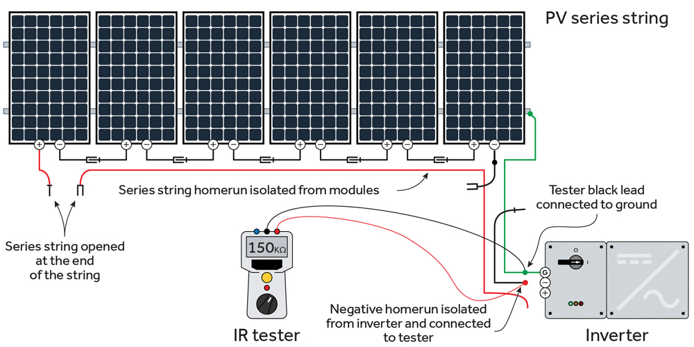
Here, we’re testing the insulation resistance of the negative homerun conductor. Note that the tool displays a non-passing result. Since we have isolated the string circuit down to a single conductor, we can now assume there is damage somewhere along the negative homerun. Replace this homerun conductor, retest, and verify that the insulation resistance has risen above 1 MΩ.
RINSE AND REPEAT
Repeat the processes above for all strings in the array, retesting with the guard circuit and isolating down to the homerun conductors when necessary. Document all results to trend conductor health over time.
REFERENCE
- International Electrotechnical Commission. IEC 62446-2:2020, Photovoltaic (PV) systems – Requirements for testing, documentation and maintenance – Part 2: Grid connected systems – Maintenance of PV systems. Available at https://webstore.iec.ch/en/publication/27382.

Lucas Miller is a Senior Engineering Consultant at Mayfield Renewables. He entered the renewables industry straight out of college by moving to Portland, Oregon, to join a PV contractor. Miller has since held many roles in the solar and energy storage industry, spanning marketing, market research, product development, and project coordination. In his current role at Mayfield, he brings his talents in research and writing and provides much of the leadership for Mayfield’s educational content development. He earned BS degrees in marketing and renewable energy engineering from the Oregon Institute of Technology.