
Designing, installing, and maintaining an adequate grounding system is as important a part of substation design and maintenance as any other. “Out of sight, out of mind” definitely does not apply here. The grounding grid is not only essential to proper function and power quality but is also critically important to worker safety as well as that of public passersby. Design is critical for establishing an equipotential environment that precludes voltage gradients anywhere around the station. Similarly, construction must accommodate fault currents without creating voltage gradients.
REMOTE EARTH
For basic grid performance, a ground test instrument must establish a sufficiently low resistance to “remote earth,” which refers to a critical distance from the station at which no further increase in distance will contribute any additional resistance. Once a fault current has escaped the immediate environs around the station, the expanse of earth has become so vast there is no measurable increase in resistance with distance. “Remote earth” may be comparatively near or far, depending on variables such as the size and construction of the grid, local soil type and conditions, and other factors. Similarly, safe step and touch potentials must be established for the protection of workers and the public during fault conditions. Step potential is the distance between a person’s feet and touch potential is the voltage between the energized object, such as a substation fence, and the feet of a person in contact with the fence. The ground grid must be such that these potentials cannot rise to an injurious level, even under maximum fault conditions for that substation.
The establishment of a good ground begins with the earth itself; that is to say, the electrical properties of the soil and its ability to carry return current and disseminate fault currents. This characteristic is termed resistivity, depends on soil structure and extant conditions, and varies enormously across the spectrum of soil types. Soil resistivity is a volumetric measurement and is expressed most commonly as Ohm-centimeters (Ω-cm), although other units, such as Ohm-inches, are also found in the literature. The measurement can range from hundreds to nearly a million. Local conditions, mainly moisture and water content, are superimposed upon soil structure and can create substantial fluctuations around the calendar as well as daily.
SOIL RESISTIVITY
Substation grounding begins with measuring soil resistivity at the site. Be sure to have a four-terminal ground resistance tester. This vital piece of test equipment is also available in three-terminal models, which will test resistance to remote earth, as mentioned above. However, they cannot measure soil resistivity. That requires a four-terminal tester.
To be valid, the test must follow a prescribed method. Several exist, mainly to accommodate space limitations, but by far the most widely used is the Wenner method (Figure 1).
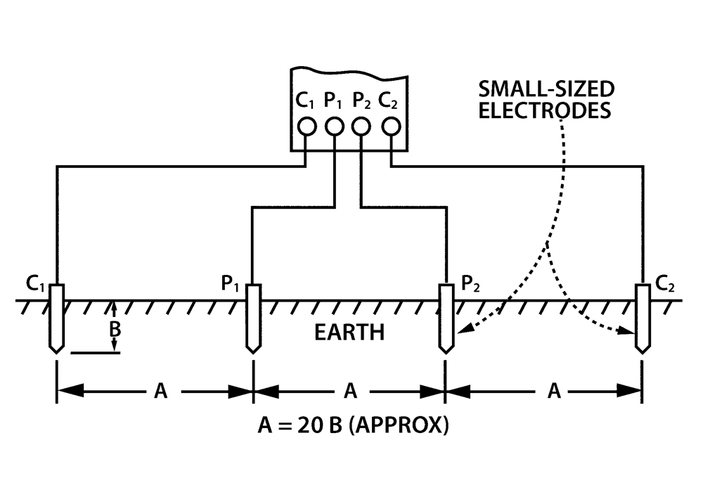
The four terminals are connected to leads and probes that are driven into the ground at equal spacing in a Kelvin bridge configuration, with current probes on the outside and potential probes inside. The tester measures between the potential probes. The measurement is then applied to a formula, ρ = 2 πaR, where a is the spacing between the two internal probes and R is the reading from the meter. The calculation produces a volumetric measurement in units of ohm-centimeters (Ω-cm), although other units are sometimes used. This is average soil resistivity to depth “a.” A low number is cause for celebration, as the grid will require less metal and less design work. High numbers are a challenge but can still be attained. There will just be that much more metal in the ground.
GRID DESIGN
Having collected the data, it can now be utilized in designing the grid. Modern conveniences have vastly improved what was once a time-consuming and tedious process performed with pencil and paper and a slide rule. Software programs are readily available where you need only enter the resistivity measurement along with relevant data such as the rods to be used and dimensions of available area. Finally, the desired resistance goal is entered. Substations generally call for a 1.5 Ω ground resistance to remote earth. Some more demanding sites may require 1 Ω or occasionally even less. The software then calculates and describes the electrode that will meet these requirements.
Connections
The job is not done. All metallic structures and components must be connected to create a Faraday cage where everything is at equipotential. It is not enough to have the ground grid just under the station. It must extend beyond the fences by several feet. This protects passersby from step potential (voltage between the feet) and touch potential (voltage between fence and earth surface) should the person touch the fence or walk by during a fault clearance event.
Typically, conductors are bare-stranded copper or copper-clad steel, with minimum wire size for a distribution grid at #1/0. Transmission substations have greater demand, so conductor wire sizing is increased to #4/0. These measurements come from a standardized wire gauge (AWG) system used mostly in North America to determine the size of electrically conducting wire.
Electric utilities must maximize grid efficiency to maintain a safe equipotential distribution across the entire structure. Accordingly, testers must establish a firm electrical connection at every crossover point. The conductors are arranged in a square pattern, with spacing dependent on soil resistivity. Soils of low resistivity require fewer rods; hence the spacing can be less dense, typically up to 15 feet in high-conductivity soils. For transmission substations, spacing is reduced to 10 feet. Additionally, equipment and switchgear will require some special connections.
Testers must also account for the opening and closing of gates so as not to affect the electrical integrity of the grid. Utilities must prioritize facility expansion or the addition of equipment to avoid disrupting the equipotential balance across the grid. Separate grounds should never be installed, as these can develop dangerous potential between them.
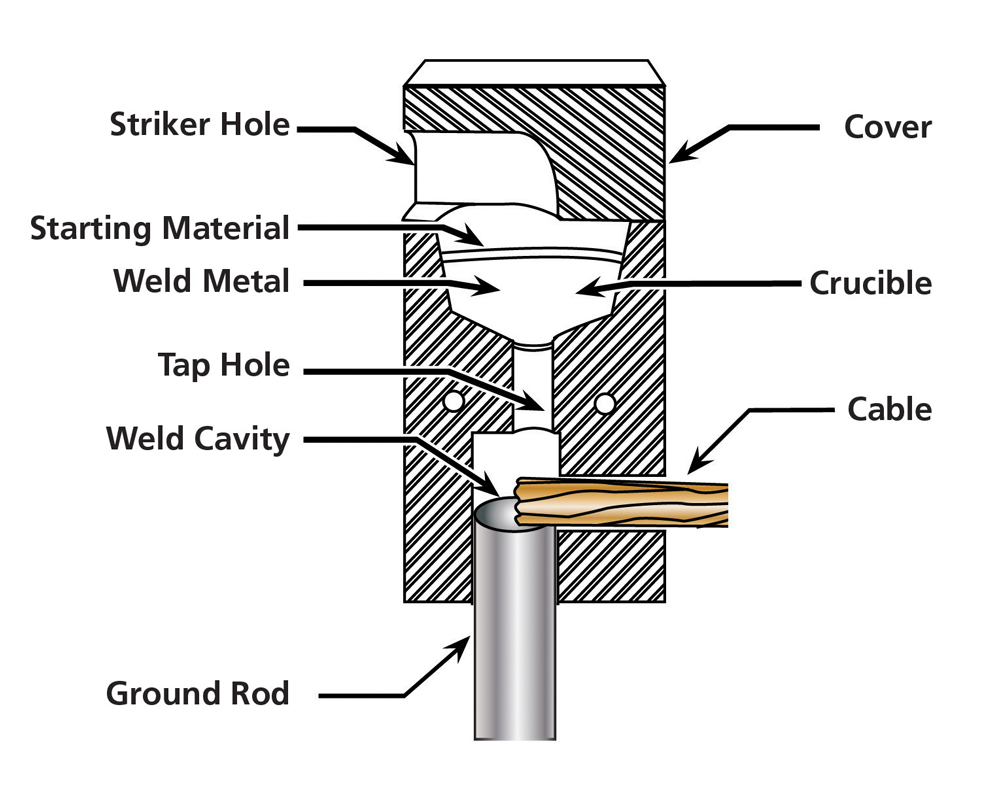
Tying together sections of mesh from a pre-manufactured grid can save time and work as the individual crossover connections are already installed and individual lengths of conductor do not have to be laid out. A typical example of a mesh consists of 2×2-foot squares or 2×4-foot rectangles of #6 (American wire gauge or WG-type) copper, 20 feet wide. Any number of these sections of mesh may be required — and carefully connected together — to underlie the entire station and meet the grounding resistance mandate. Next, additional ground rods (Figure 2) can be installed by bonding to the mesh to augment the grid and meet specified resistance.
Additional rods have the advantage of requiring little additional surface area as they are vertically deep-driven. If they hit the water table, all the better; water is a relatively stable supply of a good conductor. Ground rods are typically electroplated copper, driven at crossover points, adjacent to equipment, and around the perimeter. Eight feet is a common size, but these can be coupled and driven to greater depths to achieve specified resistance. Paralleling multiple rods, of course, has the same effect. Rods should not be placed too close to each other, as their electrical fields begin to coalesce, and the two rods start to act as one, defeating the purpose. They should be placed at least as far apart as their length. Especially difficult soils can add another dimension to the construction, making it increasingly challenging to meet specifications. Enhanced techniques are available for such situations. A bore hole can be drilled and filled with a ground enhancement material, such as bentonite or others available on the market. These materials generally retain a moist atmosphere around the rod. The ground rod then has a more stable conductive environment around it.
Connections must meet the challenge of being able to pass enormous current surges, such as a lightning strike, without opening up. If connections opened under heat and stress, a dangerous potential gradient could be established across the broken connection and equipment bonded to it. A variety of connections may be used above grade, including compression and wedge-type connectors and exothermic welds (Cadwelds). Below grade, exothermic welds are most effective.
Grid Surface
Indoor substations may be above ground, at ground, or at basement level. In these cases, the gird is usually encased in the concrete floor. Grounding may be augmented by a closed loop of copper or aluminum bars around the inside walls, of .5-inch by 1.5-inch dimensions. Outdoors, the grid is commonly buried 1–2 feet, with the surface covered by 3–6 inches of crushed stone, asphalt, or concrete. Crushed stone generally has one hundred times the resistance of concrete.
Therefore, the surface covering is generally augmented by the addition of another 18 inches of material. A thick surface covering adds protection for step potential, especially when stepping onto remote ground around the perimeter. For cases where the surface must be concrete and cannot be covered with crushed stone, augmented protection is achieved by an additional wire mesh embedded just below the surface. Prefabricated mesh is handy for this purpose and then bonded to the main grid buried deeper below. Due to water content, concrete does not offer the resistance one might presume. Therefore, the addition of the mesh significantly improves the equipotential quality of the surface. Similar installation of mesh adds protection to areas where switches are operating.
CONCLUSION
As documented here, the grounding electrode, generally in the form of a buried grid, is an essential element in the proper and safe functioning of a substation. Maintenance personnel must conscientiously follow the well-thought-out and available industry standard parameters for design, installation, and testing to achieve effective grounding protection.

Jeffrey R. Jowett is a Senior Applications Engineer for Megger in Valley Forge, Pennsylvania, serving the manufacturing lines of Biddle, Megger, and Multi-Amp for electrical test and measurement instrumentation. He holds a BS in biology and chemistry from Ursinus College. He was employed for 22 years with James G. Biddle Co., which became Biddle Instruments and is now Megger.