
Utility substations are undergirded by large — sometimes massive — grounding grids. These are made up of electrodes, much like the familiar ground rod, but with extended responsibilities. The grid must provide a means to carry electrical currents into the earth under normal and fault conditions without exceeding operating and equipment limits. The grid must also assure the safety of passersby from step- and touch-potentials during normal operation as well as fault conditions.
In substations, a grid or a mat system is usually used. These consist of horizontally interconnected bare conductors attached to vertically driven ground electrodes or plates. Structures, frames, equipment neutrals, and fault current sources like surge arresters and capacitor banks are then connected to this grid or mat system.
The purpose of a properly designed, installed, and maintained grounding system is to eliminate shock hazards and abnormal operating conditions that may arise from fault currents. During fault conditions, the earth can become saturated by currents emanating from the grid. The potential gradients produced are proportional to the magnitude of the grid current and the resistance across the path of the ground current.
Step and touch potentials define the limits of such potentials. While there are no specific code requirements, applicable safety standards are available from recognized independent authorities.
- NFPA 70E, Standard for Electrical Safety in the Workplace, states that the path to ground from circuits, equipment, and enclosures shall be permanent, continuous, and effective. This includes a continuing maintenance requirement, not just at the time of installation.
- OSHA has adopted this requirement from NFPA 70E as a specific safety protection for employees in the workplace in OSHA 1910.269, Electric Power Generation, Transmission, and Distribution.
- IEEE Std. 81-2012, IEEE Guide for Measuring Earth Resistivity, Ground Impedance, and Earth Surface Potentials of a Grounding System, states that the objective of testing the integrity of the ground grid is to determine whether the various parts of the grid are interconnected with a low-resistance connection.

GROUNDING TESTS
Two tests are necessary to establish and maintain a safe and effective grid.
Remote Earth Resistance Test
The most familiar test verifies the resistance to remote earth, defined as the resistance a fault current will encounter in passing from the grid into the surrounding soil. Obviously, it should be kept as low as possible. Smaller substations often require less than 1.5 ohm; larger ones often less than 1 ohm. The term “remote earth” means the resistance of the surrounding soil to a point beyond which there is no increase, no matter how far out you carry the test. This is because as you move away from the substation, the expanse of soil increases geometrically. Fault current does not have to travel in a straight path as circuit current does, so at some point from the substation, the expanse of soil becomes so vast that there is no appreciable increase in resistance no matter how much farther you go. This distance, referred to as remote earth, is indispensable to ground resistance testing.
Maintenance Testing
A second test, often overlooked but equally important, is used to determine the health of the grid — maintenance testing of the grid itself. “Out of sight, out of mind,” is a familiar proverb that can be costly here. In the event of a lightning strike or fault condition, the grid can be subject to enormous currents and electrical stress. Although it may do its job perfectly well at the time, the remaining structure can be critically damaged. It is not the same as it was before the event.
On a less dramatic scale, there is normal aging. Seasonal cycles of freezing and thawing exert physical pressures on the grid. Normal operation can gradually weaken joints and welds. Electrolytic action in soil can corrode metals. Like any other piece of electrical equipment, the grid should be routinely tested and maintained.
Testing grid integrity requires high current and low resistance across joints and welds that are part of the equipment, frame, structure, or enclosure grounds. A 300-amp test current is the industry standard, and resistance values should be below 100 µΩ (micro-ohms). As the test current is passed through the grid, the voltage drop and current magnitude and direction are monitored.
To perform the test, a reference ground point is established, preferably a transformer neutral. One test lead is connected to the grid under test; the second lead is connected to the reference ground below any bonding connections. After 300 amps are passed through the grid for at least 3 minutes, a clamp-on ammeter is used to trace current flow and magnitude (Figure 1).
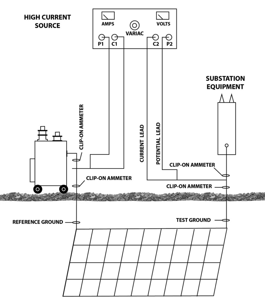
Current is measured as it flows into the grid (below the test lead) and into the equipment, structure, and frame. This determines the magnitude and direction of current flowing in the ground grid circuit as well as that flowing in enclosures, frames, foundations, and so forth. Finally, the test leads are shorted together and 300 amps are passed for 3 minutes. The voltage drop of the leads is noted. This value is subtracted from the voltage recorded during the test. To verify good connections, the voltage should drop approximately 1.5 volts for every 50 feet of straight-line distance. At least half of the test current should return to the source via the grid to the ground under test. Return current of less than half indicates a potential bad ground connection. The grounded points should be tested one at a time to verify integrity.
CASE STUDY
We can examine some typical test results indicating a good test (Figure 2). Measurements are taken before the test hookup. The reference current in the transformer neutral was 82 amps. Current in the post-ground wire was 6 amps, with a distance between the two grounds of 15 feet. Voltage drop in the test leads at 300 amps was 7.5 volts. With the measurement hookup complete and 300 amps flowing in the test circuit, current flow in the reference ground to grid was observed as 270 amps, while current flow in the reference ground to transformer was 50 amps. Current flow from grid to post ground was 280 amps while from the structure to post ground was 1 amp. The voltage reading on the test set was 7.9 volts. Current in the reference ground to grid was nearly equal to the current from the grid to the post ground, thus exceeding the 150 amp criterion. The voltage drop in the ground-grid circuit was equal to 0.4 volts (7.9 minus 7.5) for a 15-foot distance. This meets the required 1.5 voltage drop for a 50-foot distance.
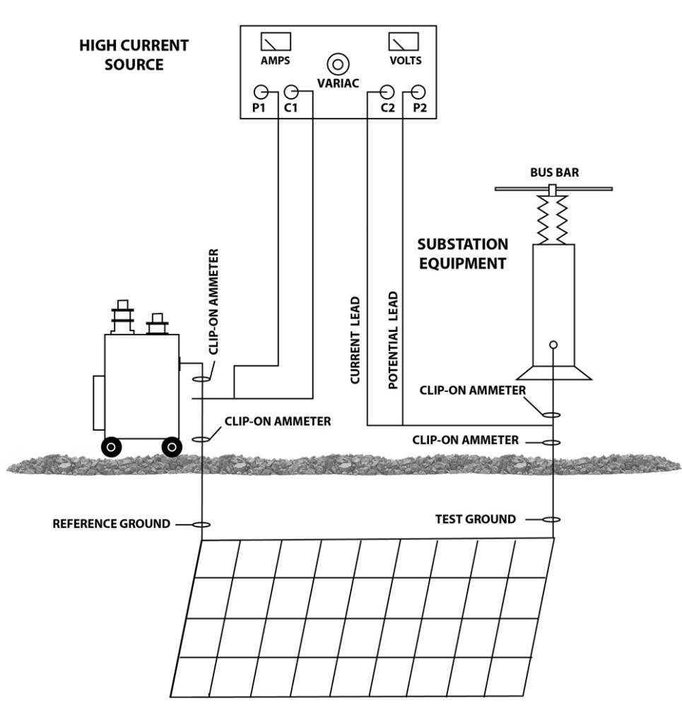
By contrast, suppose that before the test hookup, the current in the transformer neutral was again 82 amps, but there was no current in the frame ground. The distance between reference ground and frame ground is 100 feet, and the voltage drop of the test leads at 300 amps was 7.5 volts. Hookup was made, with 300 amps flowing in the test circuit. Current flow in the reference ground to grid was observed to be 270 amps. Current flow in the reference ground to transformer was 50 amps. Current in the frame ground from the grid was 2.5 amps. In the frame ground from the structure, current was 280 amps. The voltage reading on the test set meter was 15.6 volts. The current via the grid to the frame ground was only 2.5 amps, much less than the 150-amp requirement. Voltage drop in the ground circuit was 8.1 volts (15.6 minus 7.5) for a 100-foot distance. This did not meet the 1.5-volt criterion for a 50-foot distance, indicating faulty ground connections (Figure 3).

CONCLUSION
Modern testers have significantly improved in that they no longer have to be standalone instruments that spend most of their life cycle in storage, to be used once a year. The grid testing function is now integrated into a single instrument with other vital high-current applications including circuit breaker testing, primary current injection, switchgear testing, CT commissioning, and turns ratio. All relevant test data can now be displayed, making operation clearer, smoother, and notably less susceptible to error.
“Out of sight, out of mind?” Not anymore. A reliable test for grid condition can now be readily incorporated into your electrical maintenance program.
REFERENCE
A. S. Gill, PE. “High Current Method of Testing Ground Grid Integrity,” GTS 300 App Note, Bulletin -1 GGI, Multi-Amp Corp.

Jeffrey R. Jowett is a Senior Applications Engineer for Megger in Valley Forge, Pennsylvania, serving the manufacturing lines of Biddle, Megger, and Multi-Amp for electrical test and measurement instrumentation. He holds a BS in biology and chemistry from Ursinus College. Jowett was employed for 22 years with James G. Biddle Co., which became Biddle Instruments and is now Megger.