

Commissioning and maintenance procedures for low-voltage circuit breakers may include testing to determine whether the circuit breaker is able to respond correctly to faults or overload conditions as specified in the coordination study. This requirement may include ground fault (GF) as part of the protection scheme. Testing may be performed through primary or secondary injection; primary injection is the best approach.
INJECTION TESTING
NFPA 70, National Electrical Code (NEC) includes a 2017 update to Article 230.95 (C) that states that the ground fault protection system for newly installed systems must be tested using primary injection. The previous edition (2014) stated that the test was to be conducted in accordance with instructions provided with the equipment. This often left testing up to an installer who may not have had sufficient familiarity. Thus, it would have been acceptable to use a secondary injection method or merely press the trip button.
Secondary injection is a test whereby AC current is applied to the secondary side of the current transformer, essentially testing only the trip unit logic. The manufacturer’s specific secondary test kit is required, or the operator must be able to access the secondary side of the current transformer. Therefore, the method can be a time saver.
Primary injection injects an AC current through the primary coil of a current transformer, which in turn induces a proportional signal in the secondary coil or coils, thereby lowering the output signal to a level that can be handled by the protection device. All of the circuit breaker elements are being tested, including contacts, current sensors, wiring, and trip unit. Primary injection testing can be done by three methods:
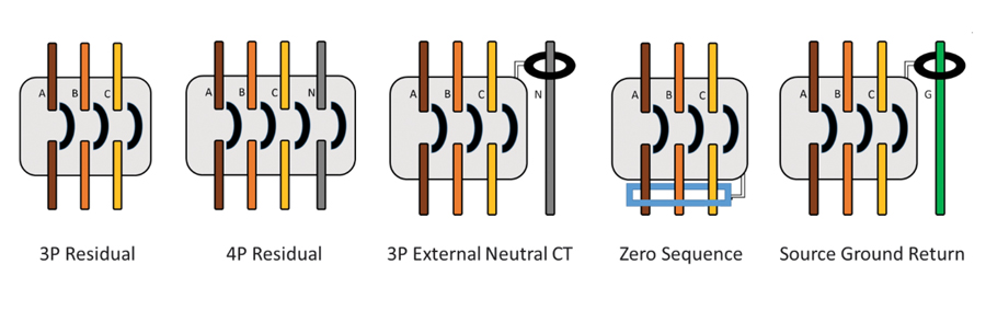
- Residual sensing can be set up as 3P, 4P, or 3P with an external neutral CT. This method utilizes vectorial summation of the currents on each phase and neutral if applicable, using separate CTs to determine a possible path to ground. With a balanced load, the resulting current flow through the ground fault protection circuit would be zero: Ia + Ib + Ic + In = 0 = no operating current. This method, which is also known as integral ground fault sensing, detects faults downstream of the circuit breaker.
- Zero sequence monitors vectorial summation, but a single CT encompasses all the phases including neutral, if applicable, and is external to the CB.
- Source ground return employs a CT on the ground conductor and monitors any ground current that is returning to the source. This method detects faults upstream as well as downstream of the CB (Figure 1).
GROUND FAULT PROTECTION
Proper installation and operation of ground fault protection includes the following tests:
Trip Test
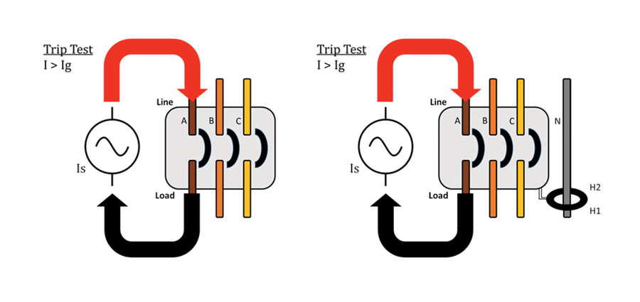
This test ensures that pickup (PU) and timing of the GF element in the trip unit are operating correctly by the manufacturer’s time current curve (TCC). If the GF element trips when the current flow direction is the same relative to the polarity marks of the two CTs, the breaker is high enough to be within the setting parameters (Figure 2).
No-Trip Test
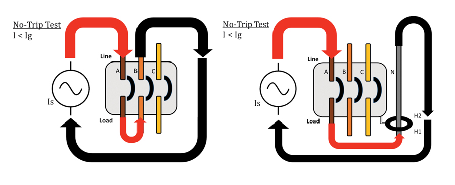
This test ensures against false tripping and confirms that the CTs are phased and sized correctly and the GF element is working correctly. When the current flow is in opposition to the polarity marks and setting parameters are exceeded, the GF element will not trip the breaker because the currents will have vectorially canceled each other (Figure 3).
External Neutral CT Phasing and Sizing
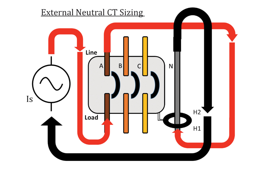
If external CTs are activated in the trip unit, they may require additional testing. CT phasing determines that polarity is correct and connections are properly terminated. CT sizing ensures that the external CT is sized to match the breaker CTs (Figure 4).
Trip Test for Residual Sensing of 3P and 3P with External Neutral
This test is performed on de-energized equipment only. The power source is isolated from the circuit breaker. All safety and lockout/tagout protocols are followed before connecting the test equipment. Nameplate information is recorded along with trip unit pickup and delay settings of all protection elements. Zone interlocking may need to be defeated before testing. All long, short, and instantaneous settings are set at maximum. The GF pickup is set at minimum. The GF delay is set at 0.2 or 0.3. Setting it at minimum may cause a nuisance trip; a slightly higher setting may be required for timing accuracy. For 3P breakers with external neutral CT, the CT phasing check and sizing will need to be conducted before proceeding.
The test set is then connected with the output lead (polarity lead) connected to the line side of the A-phase of the breaker and the return lead (common lead) connected to the load side. Here, the pulse method is more accurate than the run-up method. Current is applied starting at 70% of the expected trip value in 10-, 15-, or 20-cycle pulses depending on the GF delay setting. Current is increased with each pulse until the breaker trips or exceeds the accuracy percentage of the maximum trip current on the TCC. Reset the breaker and decrease the current per pulse if further accuracy is needed. Once the GF pickup has been determined, the GF delay is tested by applying 150% of the GF pickup. Current is applied longer than the GF delay setting. This can be accomplished with the continuous mode. Trip time is then compared against the TCC, the breaker reset, and the process is repeated on B and C phases (Figure 2).
No-Trip Test for Residual Sensing of 3P and 3P with External Neutral
This can be conducted after the trip test for 3P configuration. For 3P with external neutral CT, this test is conducted during the CT phasing. The output lead of the test set is connected to the line side of A-phase and a jumper is connected from the load side of A-phase to the load side of B-phase. The return lead is connected to the line side of B-phase. Apply 125% to 150% of the GF pickup setting for longer than the GF delay. Example: GF PU = 500 A and GF delay = 0.3 seconds. The test is conducted at 750 A for 10 seconds. The breaker should not trip. This indicates that the CTs are phased properly and the trip unit is responding correctly. The process is repeated on phases B to C and C to A (Figure 3).
External Neutral CT Phasing and Sizing
This process ensures that CT polarity and ratio are correct. The output Lead of the test set is connected to the line side of A-phase, and a jumper is connected from the load side of A to the H1 side of the neutral CT. A return Lead is connected to the H2 side. Apply 125% to 150% of GF pickup setting for longer than GF delay. Example: GF PU = 500 A and GF delay = 0.3 seconds. The test could be conducted at 750 A for 10 seconds. The breaker should not trip. If the breaker does trip, verify the neutral CT orientation, trip settings, line/load termination configuration, and wiring. Sizing of the CT is performed to ensure that the external neutral CT is properly sized with the internal breaker CTs. Connect the output Lead to the load side of A and a jumper from the line side of A to the H1 side of the neutral CT. Connect the return lead to the H2 side. With this configuration, the current sensed by the trip unit should appear as double the injected current and trip the breaker at half of the trip setting. Using the pulse method, the pickup value should be half of the trip setting. Example: GF PU = 500 A; current injected approaching 250 A will look like 500 A to the trip unit if the ratios are matched between the external and internal CTs (Figure 4).
The accuracy, sensitivity, and importance of CB testing make instrument selection and test conditions all the more important. CB testers aren’t just plug-and-play instruments. For instance, the power source must be carefully considered. The evaluation must include harmonics, generators, and inverters.
- Harmonics. Testers with solid-state components or sensitive metering can experience disruption of controls by harmonics. Keep circuits separate respecting server racks, high-frequency radios, and VFDs. Power conditioners can alleviate these hazards.
- Generators. There are limitations on block loading the engine and voltage regulator. The instant request for large amounts of power output causes the engine and excitation system to have to work harder to maintain proper frequency and voltage. How the generator accommodates this demand may affect the output of the primary injection test set, interrupt current flow, and cause irregular test results. It may be beneficial to only load the generator to 50% of capacity. Generators can also be a source of harmonics.
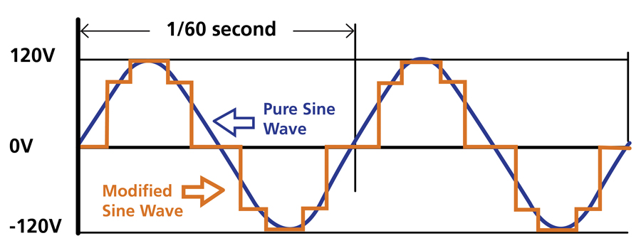
- Inverters. There are two basic inverter designs: modified sine wave and pure sine wave. Modified sine wave should not be used on sensitive electronics as the sine wave in this instance is more of a square wave signal and appears choppy on an oscilloscope. Pure sine wave units are essential for sensitive electronics. This can greatly affect the zero crossing when it comes to the firing angle of the primary injection instrument as it pertains to eliminating or reducing DC offset (Figure 5).
CIRCUIT BREAKERS
Circuit breakers have multiple configurations and characteristics that must be understood and considered.
Connection Method
CBs can be installed with busing or cabling and also terminated with the feeding to the top side of the breaker. Attention must be paid to ensure the connections are made correctly. Best practice would be to inject current from the line to the load side. Verification of internal CT polarity may be necessary when testing with an external neutral CT. There may be negative factors involving the connection between the test set and the breaker, including cabling, busing, bolts, vise grips, or lugs. Crimped cables and multiple lugs can cause added impedance, which will affect the output of the test set. Custom-made cables should be checked with a low-resistance ohmmeter to verify a solid connection between cable and crimp.
Low-Voltage Circuit Breakers
Two types of LV circuit breakers utilize ground fault protection: molded case circuit breakers (MCCB) and power circuit breakers. Certain features may need to be disabled during testing.
- Thermal memory accounts for heating and cooling before allowing reclosure. Each manufacturer has a specific means of disabling and may require a manufacturer’s specific secondary injection test set or jumpers. MCCBs typically do not have a bypass means.
- Zone selective interlocking is used to communicate with upstream and downstream breakers. It may need to be disabled during testing to eliminate interference with the accuracy of the test or affecting other breakers in the system.
- Under-voltage coil must be disabled for primary injection testing. Disabling methods include removal or applying a mechanical interlock override tool.
- Maintenance mode switch is used to reduce arc hazard during maintenance by lowering trip settings to a safer working level. Determining whether the breaker being serviced is controlled by a maintenance switch can be referenced in the manufacturer’s user manual. Test results can be negatively affected if a maintenance switch is on during testing, and the breaker may need an external power source to activate this feature. This can present a safety hazard, as primary injection testing is performed only on de-energized equipment.
TRIP UNITS
Trip units are electronic or solid-state devices used to set parameters to protect the breaker, loads, and personnel as well as a multitude of other functionalities. It must be determined whether the CB under test is equipped with ground fault sensing before commencing testing. Most trip units will have a dial used to set GF pickup and delay or a menu item in the display. If neither a dial nor menu item are present, then the breaker is likely not equipped with ground fault sensing. Trip units may be powered by external power sources. Powering up the trip unit should not be required for GF testing but may be necessary to verify settings and the last trip. Two primary injection test sets may be needed to power up a single phase while testing another.
Testing cables also need to meet relevant parameters. For GF testing, cables are preferred over bussing because of flexibility and the NEC 230.95 (A) requirement of only 1,200 A. Minimizing length reduces total impedance and reactance. Cables with the same current direction should be kept away from each other. Twist cables of opposing currents to minimize magnetic flux which in turn reduces reactance. Utilize higher open circuit voltages when available and avoid loops.
SUMMARY
Ground faults can be catastrophic, so having well-maintained breaker protection is paramount. The potential consequences of a ground fault occurrence can be reduced to no more than a simple shutdown. The primary injection method is preferable for maintenance testing because it includes all the elements of the circuit breaker involved, not only the trip unit.
Acknowledgment: The author thanks Megger Engineers Daniel Carreño and Aaron Tucker for their contributions to this article.

Jeffrey R. Jowett is a Senior Applications Engineer for Megger in Valley Forge, Pennsylvania, serving the manufacturing lines of Biddle, Megger, and Multi-Amp for electrical test and measurement instrumentation. He holds a BS in biology and chemistry from Ursinus College. He was employed for 22 years with James G. Biddle Co., which became Biddle Instruments and is now Megger.