
A numerical protection relay provides multiple functions and typically uses algorithms that do not work on the same principles as older electromechanical relays. Numerical relays are often still tested using old techniques developed long ago for electromechanical relays. One such common technique is referred to as a “static test.” Fault voltage and/or fault current are injected to see whether the selected protection function operates at the setpoint and is in tolerance. Some protection functions have dynamic characteristics, and if a static test is applied, then the true performance of the selected function may not be properly tested.
A good example is a mho distance element that is polarized using memorized positive-sequence voltage. The mho circle actually expands during an actual fault and has more resistive coverage, which is dependent on the apparent source strength. Static testing is only useful to measure the reach point setting along the line angle and the line angle setting itself. A dynamic test usually consists of a pre-fault condition and a fault condition. Table 1 illustrates a simple two-stage dynamic test for a three-phase fault on a distribution feeder.
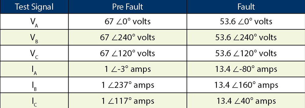
Table 1: Dynamic Three-Phase Feeder Fault
This article demonstrates the benefits of dynamic testing and provides some examples of how to apply them. Assume that all values shown are secondary unless otherwise noted.
Power System Models
Typically, signals the relay would measure must be injected during an actual power system fault to perform a dynamic test. Therefore, you can use a simple model power system to dynamically test a numerical protection function. The following parameters would generate the three-phase fault signals shown in Table 1. ES is the apparent source voltage. ZS is the apparent source impedance. ZL is the feeder impedance.
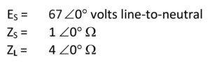
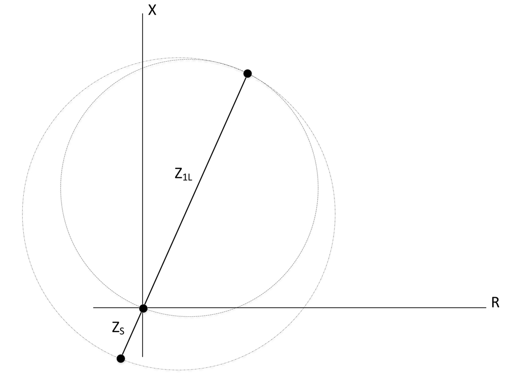
Figure 1: Dynamic Mho Characteristic versus Static Mho Characteristic
Static characteristic = Inner Mho Circle
Dynamic characteristic = Expanded Mho Circle
Stator Ground Fault Protection Using Sub-Harmonic Voltage Injection
Total (100 percent) stator ground fault protection is provided by injecting a 20 Hz voltage signal into the secondary of the generator neutral grounding transformer through a band-pass filter. The band-pass filter passes only the 20 Hz signal and rejects out-of-band signals. The main advantage of this protection is 100 percent protection of the stator windings for ground faults, including when the machine is off-line (provided that the 20 Hz signal is present). Conventional test methods do not apply to this special protection. This section shows how to use the power system model to calculate test signals for this protection function.
Figure 2 illustrates a typical application where a 20 Hz voltage signal is impressed across the grounding resistor (RN) by the 20 Hz signal generator. The band-pass filter only passes the 20 Hz signal and rejects out-of-band signals. The voltage across the grounding resistor is also connected across the voltage input (VN) of the 64S relay. The current input (IN) of the 64S relay measures the 20 Hz current flowing on the grounded side of the grounding transformer and is stepped down through a CT. It is important to note that the relay does not measure the 20 Hz current flowing through the grounding resistor. The 20 Hz current increases during ground faults on the stator winding, and an overcurrent element that operates on this current provides the protection.
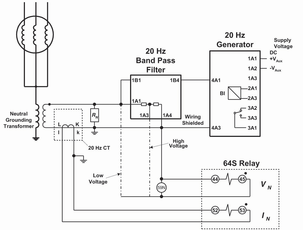
Figure 2: 20 Hz Injection Grounding Network
The following series of equations shows how to model and calculate the 20 Hz voltage and current measured by the 64S relay.
Grounding Transformer Turns Ratio (N)
Assume that the turns ratio of the grounding transformer is equal to:
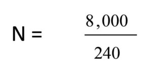
(1)
Capacitive Reactance
The total capacitance to ground of the generator stator windings, bus work, and delta connected transformer windings of the unit transformer is expressed as C0. Generator step up transformers have delta connected windings facing the generator, so capacitance on the high side is ignored. The corresponding capacitive reactance is calculated as follows:
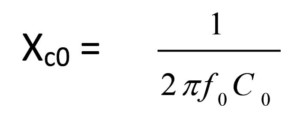
(2)a
The capacitive reactance for 1 micro-Farad is equal to:
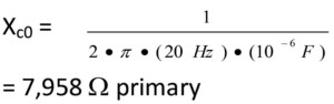
(2)b
Reflect the capacitive reactance to the secondary of the grounding transformer:
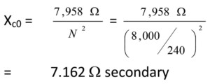
(2)c
Grounding Resistor (RN)
The ohmic value of the grounding resistor can be sized as follows so as to avoid high transient over-voltage due to ferroresonance:
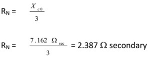
(3)
A value of 2.5 ohms secondary is used for this example.
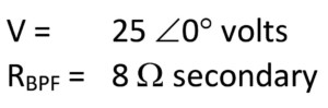
20 Hz Signal Generator and Band-Pass Filter Characteristics
Assume that the 20 Hz signal generator outputs 25 volts. The band-pass filter has a resistance equal to 8 ohms.
(4) & (5)a
Stator Insulation Resistance (RS)
RS is the insulation resistance from the stator windings to ground. A typical value for non-fault conditions is 50,000 ohms primary.
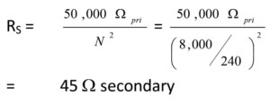
(5)b
Current Transformer
The current input (IN) of the 64S relay measures the 20 Hz current flowing on the grounded side of the grounding transformer and is stepped down through a CT.

(6)
Grounding Network
All of the elements needed to mathematically represent the grounding network and determine the 20 Hz signals measured by the 64S relay are now available. Figure 3A shows the insulation resistance and the stator windings referred to the primary of the grounding transformer. Figure 3B shows the insulation resistance and the stator windings referred to the secondary of the grounding transformer.
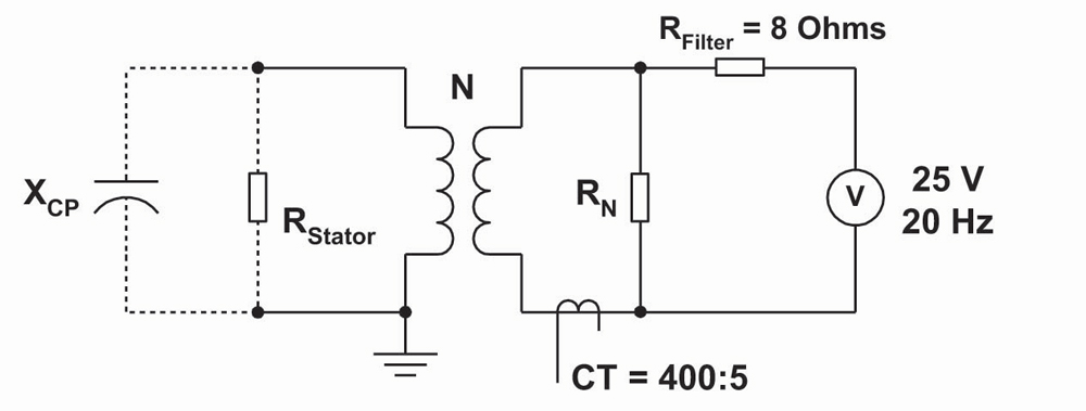
Figure 3A: 20 Hz Grounding Network Referred to Primary of Grounding Transformer
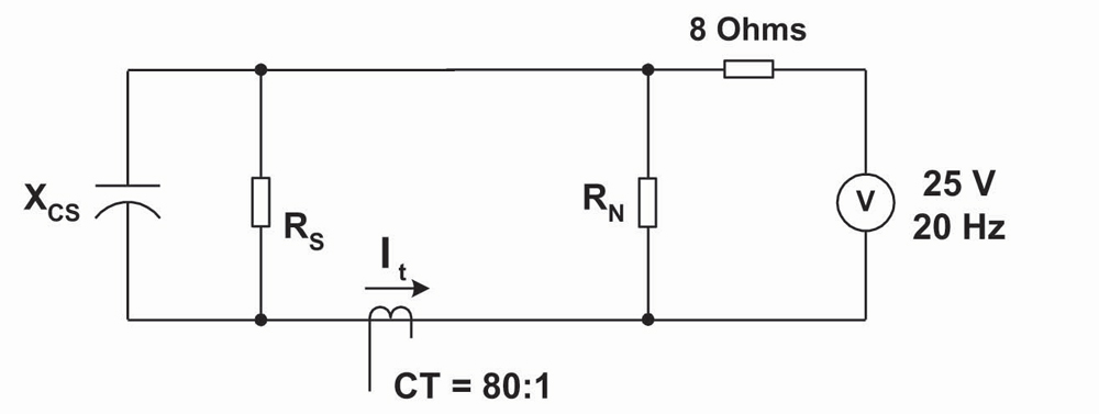
Figure 3B: 20 Hz Grounding Network Referred to Secondary of Grounding Transformer
20 Hz Current (IN) Measured by 64S Relay
The current input (IN) of the 64S relay measures the 20 Hz current flowing on the grounded side of the grounding transformer and is stepped down through a CT. As noted previously, the relay does not measure the 20 Hz current flowing through the grounding resistor.
Total 20 Hz Current Supplied by Signal Generator
The 20 Hz signal generator looks into the band-pass filter resistance (RBPF), which is in series with the parallel combination of the following:
- Zc0
- RS
- RN
Therefore, the total loop impedance of the 20 Hz grounding network can be expressed as:
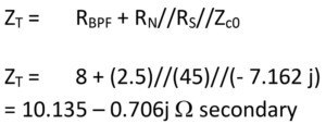
(7)
The total 20 Hz current supplied by the signal generator is determined as follows:
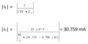
(8)
20 Hz Current Measured by 64S Relay (IN) during Non-Faulted Conditions
The 20 Hz current measured by the 64S relay is the ratio of the total current that flows into the primary side of the grounding network (Zc0//RS):
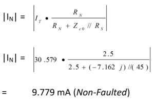
(9)
20 Hz Current Measured by 64S Relay (IN) during Ground Fault on Stator Windings
A typical value to represent the insulation resistance of the stator windings breaking down during a ground fault is 5,000 ohms primary. If the calculations for equations (7) through (9) are repeated for a fault resistance equal to 5,000 ohms primary (4.5 ohms secondary), then the 20 Hz current measured by the relay is as follows:
![]()
If the calculations for (7) through (9) are repeated for a fault resistance equal to 1,000 ohms primary (0.9 ohms secondary), then the 20 Hz current measured by the relay is as follows:
![]()
Table 2 summarizes the 20 Hz current measured by the relay for non-faulted and faulted conditions. Use these values to test the function.
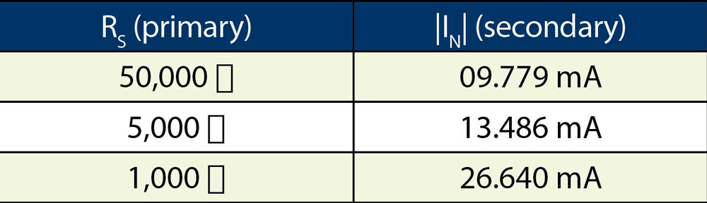
Table 2: 20 Hz Current Measurements
Hidden Features and COMTRADE Playback
Numerical protection functions often have hidden features the user may not be aware of when testing the relay. A good example is how a generator differential protection function provides proper restraint to prevent a misoperation during a black start.
Black Start and Generator Differential Protection
This section provides such an example where a backup numerical generator protection relay misoperated during a black start. The primary numerical generator protection relay properly restrained due to having a CT saturation detector built in. The current waveforms captured by the numerical relays can be played back to test that the backup relay works properly after modifying the protection settings. This playback can also be used for generator relays at other locations that also have black start capability.
What Is Black Start?
A black start is the process of restoring a power station to operation without relying on external power sources. An off-site power source is not available during a wide-area outage. Therefore, a black start is required in the absence of grid power. Generator relay current inputs are subjected to high levels of dc offset and harmonic current due to energizing the step-up transformer during a black start. If the system side and neutral side sets of current transformers do not have the same saturation voltage characteristics and there is a large dc offset present in the inrush current, then the current transformers can saturate with restraint current significantly less than two times the nominal relay current.
Generator differential protection must have special built-in measures to account for CT saturation, thus preventing unwanted tripping. An easy method to test CT saturation detectors is via COMTRADE playback. COMTRADE playback is a form of dynamic testing, since you are injecting actual fault signals recorded during a system event. This is a very practical method to check that any protection function potentially affected by transformer inrush is properly set.
Figure 4 shows the switching configuration for an actual black start. The step-up transformer is normally energized from the 230 kV transmission grid. This particular test was performed to prove that the generating company can pick up the station service transformer for essential loads, such as the sluice gate spillway supply, should a system blackout occur. This is considered to be a dead bus operation. The transmission company opened the step-up transformer high-side breaker and the generators continued to turn at speed with no load. The plant was attempting to only pick up station service; however, the step-up bank had to be picked up as well, since the plant cannot remotely isolate the step-up transformer.
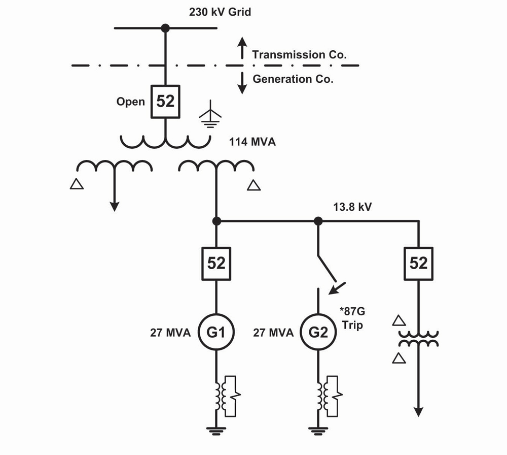
Figure 4: Black Start at Hydroelectric Plant
Review of the oscillography captured by the relay that misoperated revealed that there was significant mismatch present in A-phase and C-phase CT secondary currents from both the neutral (Iabc) and system (IABC) sides of the generator windings. The mismatch was due to the different voltage class ratings for the neutral and system side CTs. Figure 5A and Figure 5B show the individual differential currents for A-phase and C-phase. It can be seen that Ia is more saturated in comparison to IA if the 9th positive peak in Figure 3A is examined. Figure 5C is the same as Figure 5B, but all three signals (IC, Ic, C_Ph_DIFF) are superimposed onto the same channel.
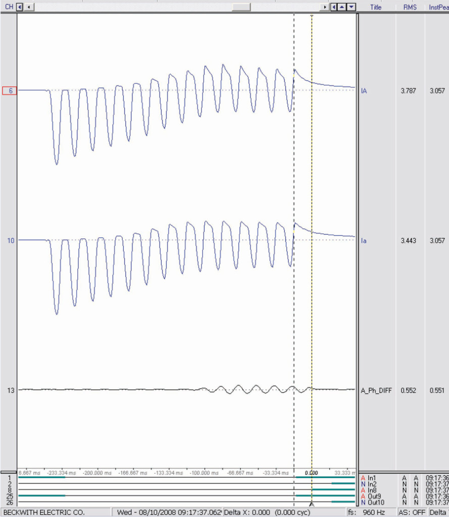
Figure 5A: A-Phase Differential Current
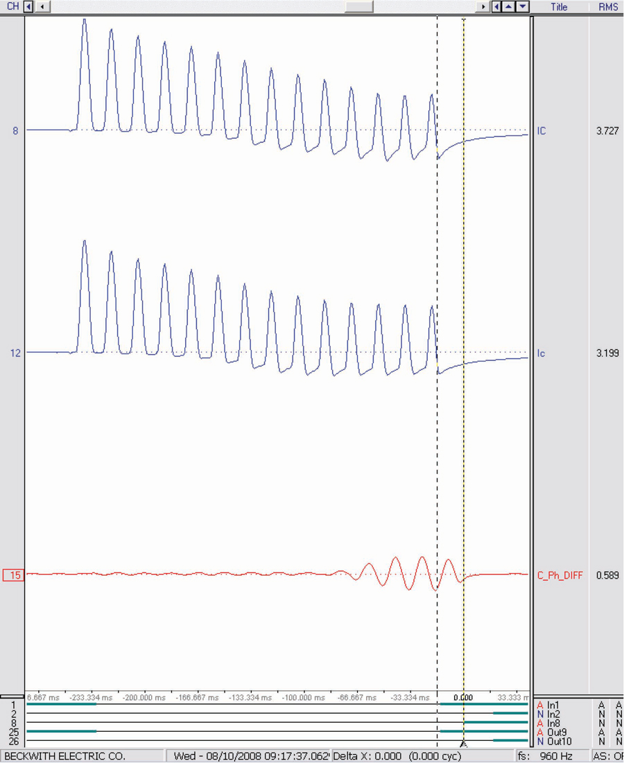
Figure 5B: C-Phase Differential Current
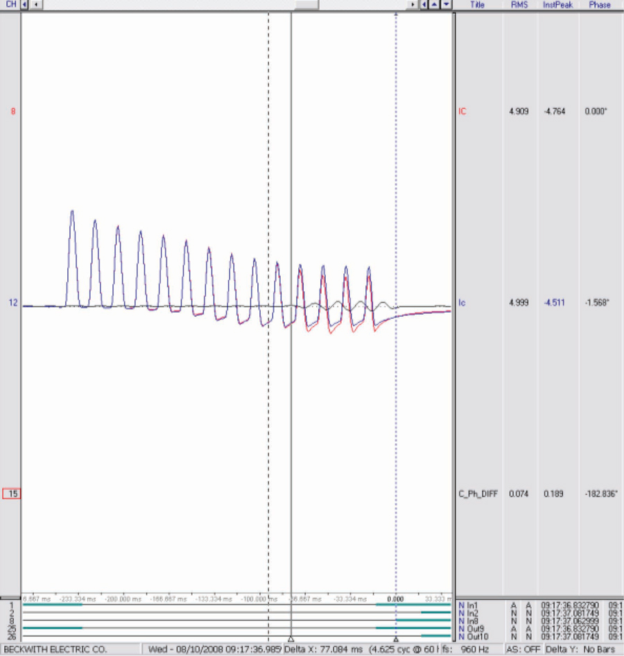
Figure 5C: C-Phase Differential Current (Superimposed)
The primary numerical generator protection relay phase differential protection used for this particular application has a CT saturation detection algorithm to improve security. If there is dc offset present, CTs can saturate with restraint current significantly less than two times nominal. The primary numerical generator differential protection automatically multiples the slope by four times (see Figure 6) if the total RMS differential current is greater than the fundamental differential current. The total RMS differential current calculated by the relay contains dc and the 1st through 5th harmonic components.
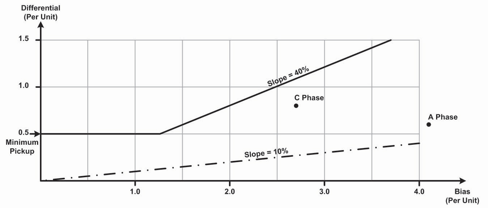
Figure 6: Generator Differential Protection Characteristics
Arc Fault Protection
It is extremely difficult to model an arcing fault even with the use of advanced transient simulation tools such as the Alternate Transients Program (ATP). COMTRADE playback is an extremely valuable tool for testing arc fault protection. One customer captured a long event where an undetected intermittent arcing fault eventually evolved into a three-phase fault and completely destroyed the machine.
Arcing faults can occur due to dirty insulators or broken strands in the generator stator windings. If undetected, such faults can lead to overheating along with catastrophic electrical failure. These events typically require extensive repairs with an extended shutdown of the machine. It is highly desirable to detect such faults at an early or incipient stage so that remedial action can be taken before a complete failure occurs. A common practice for large synchronous machines is to limit the ground fault current through the generator stator windings by grounding the neutral through a grounding transformer with a resistor connected across the secondary winding. The neutral resistor is reflected to the primary and provides high-resistance grounding during single phase-to-ground faults and is typically sized to limit the ground fault current from 3 to 25 amps primary. The ohmic value of the grounding resistor is selected to avoid high transient voltage due to ferro-resonance. Figure 7 illustrates how the stator windings are grounded through high impedance using the grounding transformer and grounding resistor across the secondary.
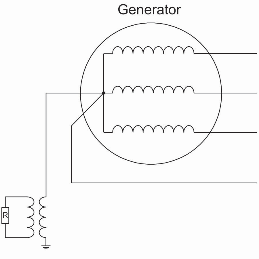
Figure 7: High-Impedance Grounded Stator Windings
An arcing fault is intermittent, and if the duration of each arc is shorter than the conventional 100 percent stator ground fault protection time delay on pickup, then no trip occurs. Figure 8 illustrates the logic for a new method of arc protection, where 59N is the neutral overvoltage protection.
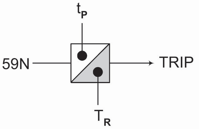
Figure 8: Arc Detector Logic
Figure 9 shows a typical timing sequence for a trip during an intermittent arcing ground fault.
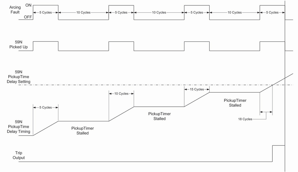
Figure 9: Timing Sequence to Trip During Arcing Fault
The reset timer (TR) has memory and stalls the delay on pickup timer (tp) when the initiating function pickup drops out intermittently as is always the case for an arcing fault. The initiating function that drives this logic is 59N. For the purpose of this test, the time delay on pickup was set equal to 18 cycles and the reset timer was equal to 30 cycles. Set the reset timer greater than the period when the arcing fault is off; otherwise, the pickup timer will reset prior to a trip. Figure 10 shows the arcing fault captured by the customer. The relay operated twice, and you can see the variable operating time, which is a function of both the arc and reset timer.
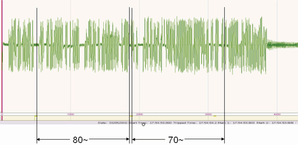
Figure 10: Arcing Fault Simulation with Variable Trip Time
Conclusion
A numerical protection relay provides multiple functions and typically uses algorithms that do not work on the same principles as older electromechanical relays. Relay test personnel often still want to use old test methods developed long ago for electromechanical relays. Test results obtained from these old test methods may not be a good indication of whether or not the numerical relay functions properly. One such obsolete technique is referred to as a static test. Fault voltage and/or fault current are injected to see if the selected protection function operates at the setpoint and is in tolerance. Many protection functions have dynamic characteristics and/or hidden features that cannot be properly tested using a static test. This paper demonstrates how to test numerical protection relays using dynamic tests, model power systems, and COMTRADE playback.
 Steve Turner is a Senior Engineer II at Electrical Consultants, Inc., working in their San Diego office. Steve worked at Beckwith Electric Company, Inc. for 10 years, first as the Engineering Laboratory Director and then as Senior Applications Engineer. His previous experience includes working as an Application Engineer with GEC Alstom and as an Application Engineer in the international market for SEL focusing on transmission line protection applications. While at Duke Energy (formerly Progress Energy), Steve developed the first patent for double-ended fault location on overhead high-voltage transmission lines and was in charge of all maintenance standards in the transmission department for protective relaying. Steve has a BSEE and MSEE from Virginia Tech University.