
Off-line partial discharge (PD) testing has emerged as a valuable diagnostic tool for assessing the insulation health of power cables, accessories, and switchgear. By detecting and measuring PD activity, this technique provides insights into the presence of insulation defects, which can lead to premature insulation failure if left undiagnosed.
Off-line PD testing is particularly useful in creating a condition-based monitoring (CBM) program, where real data on insulation integrity drives the maintenance schedule, optimizes asset life, and improves the reliability of the asset. Based on the criticality of the assets, CBM programs target the most critical assets in the grid and trigger a maintenance schedule based on the condition of these assets, rather than relying on a reactive maintenance approach.
Despite its benefits, PD testing is often viewed as complex and difficult to interpret, discouraging some utility operators and engineers from integrating it into their maintenance strategies. In reality, understanding and applying PD testing is straightforward when the fundamental principles are grasped.
This article aims to demystify off-line PD testing by detailing its mechanisms and application in CBM programs and addressing common misconceptions about its complexity. Through simplified explanations and practical examples, we demonstrate how PD testing can be a powerful yet accessible tool for ensuring safe and efficient power system operation.
PD MEASUREMENT DEVELOPMENT AND STANDARDIZATION
The initial development of partial discharge measurement dates back more than a century to the early 1900s. Since then, an earlier article in NETA World by G. C. Stone and A. Cavallini noted, “More than 8,200 papers on PD and corona measurement on HV equipment have been added to the IEEE and IEE/IET databases alone.”[1] The first commercially available test equipment was produced in the 1950s and was followed by the first international standard, IEC 60270, in the late 1960s.
Despite the overwhelming amount of information available for review and study, the application of off-line PD measurement is widely misunderstood, mostly attributed to the existence of several options to perform these measurements and the skills needed to properly analyze the results. There are several things to consider when taking PD measurements on power cables in the field. Which voltage source do I use? What does a proper calibration look like? What is PDEV or PDIV? Why do they matter? In this article, we discuss these questions and propose how PD measurement results can be used to improve the reliability of a cable system.
PD BEHAVIOR UNDER VARIOUS VOLTAGE WAVEFORMS
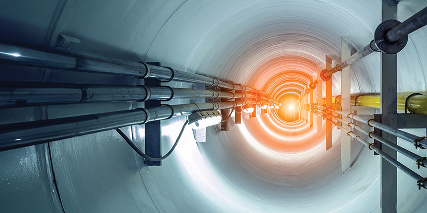
Many waveforms are available for the off-line measurement of PD on power cables. During an off-line measurement, the cable under test is connected to a high-voltage AC source, and PD detection equipment (such as a PD sensor coupled with a measurement system) is used to monitor partial discharge activity (Figure 1).

It is common to use very-low-frequency (VLF) voltages and near-power-frequency voltages for field testing due to the light weight and portability of the equipment. These wave shapes include VLF sinus, VLF cosine rectangular, and damped alternating current (DAC).
VLF Sinus
Sinusoidal VLF (0.1 HZ) sources are commonly used for the application of VLF withstand and tan delta (TD) measurements on power cables. The reduced frequency lowers the power needed to produce test voltages and allows for the use of portable, field-friendly test equipment. The polarity changes associated with this method can be susceptible to switching noise that is usually suppressed with integrated filters. The low rate of polarity change — 1 cycle every 10 seconds at 0.1 Hz — may reduce the PD repetition rate (Figure 2). Because of this, it can be hard to distinguish between PD activity from a defect and background noise.

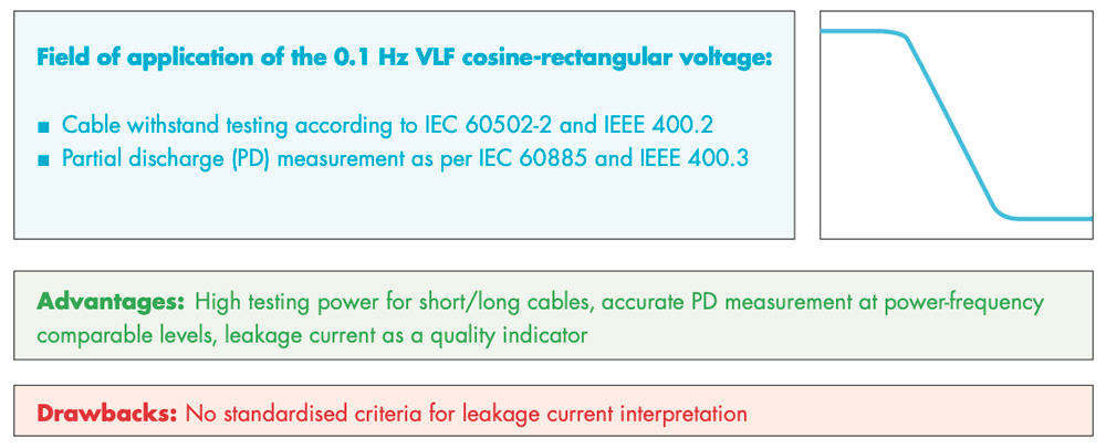
VLF Cosine Rectangular
Cosine rectangular VLF has a frequency of 0.1 Hz, but the waveform has a fast (near-power-frequency) polarity reversal followed by a DC plateau of approximately five seconds. The near-power-frequency polarity reversals can produce PD patterns similar to those under power frequency, as shown in Figure 3.
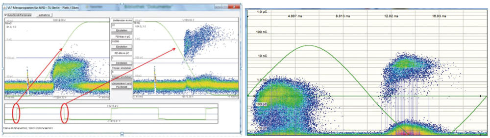
The CR waveform is often used in PD testing because it is near power frequency in terms of frequency content during the polarity reversal. The sharp rise and fall time characteristic during this event reaches the range of power frequency for field measurements effectively simulating the stress experienced during switching events or transients that commonly occur in a power system. This produces an accurate measurement of the PD event similar to power frequencies (Figure 4). Additionally, PD measurements can be combined with a VLF withstand measurement to reduce the overall testing time.
Damped Alternating Current (DAC)
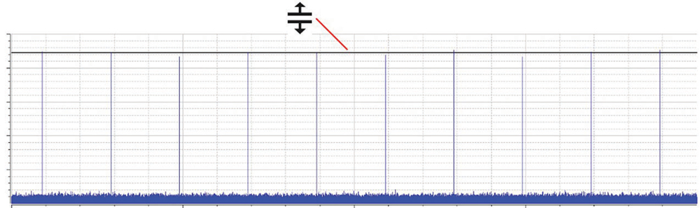
DAC voltage sources are lighter in weight and have lower power requirements than other test voltage sources. The waveform is generated by charging the cable with a continuous ramped voltage and discharging the cable’s capacitance through a suitable inductance.[2] The result is a decaying, oscillating wave that gradually experiences a lower voltage through each cycle until it reaches zero (Figure 5). Therefore, a DAC PD measurement is not applied continuously like VLF sources. During the measurement, a series of excitation shots are applied. The frequency range for the measurement is 20–500 Hz to produce results comparable to that of power frequencies.
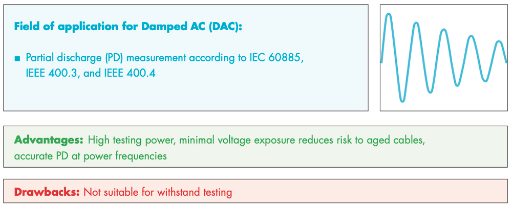
Since the cable is exposed to test voltages in short durations, the potential to prematurely age or cause damage to the cable is minimized, while remaining highly effective in identifying defects. Another benefit of using DAC is the significantly shorter overall testing time compared to any other method.
MAINTENANCE STRATEGIES
Maintenance strategies for power cables ensure reliable operation, prevent failures, and extend the lifespan of power cables. These maintenance strategies can be broadly classified into four categories.
Preventive Maintenance
A preventive maintenance strategy relies on a routine or schedule set for maintenance activities to be performed at predetermined intervals. Scheduled inspections and tests are used to prevent failures and maintain the reliability of the system. The intervals in this type of maintenance strategy are determined by the engineers based on various factors including the criticality of the asset, the type of the asset under test, recommended standards, etc.
Key practices include visual inspection to detect surface damage, cracked and discolored insulation, and environmental checks to protect power cables from moisture, rodents, and chemical exposure. Routine tests that are performed under this strategy involve the VLF (very-low-frequency) sine withstand test to evaluate the dielectric strength under 1.5Uo to 2Uo (Uo= operating voltage of cable) as recommended by IEEE Std. 400.2.
In addition, tan delta (TD) testing can be performed in conjunction with the VLF withstand test to measure the dielectric losses in the insulation, which gives a key indication of moisture ingress and early signs of aging in the insulation. All the test results obtained are trended over time to see how the insulation has performed and if any maintenance is required.
Limitations
- Determining the optimal frequency of maintenance activities is a key factor in this approach which can sometimes be challenging. If intervals are too long, then issues might go undetected and if they are too short, it can lead to inefficiencies.
- This maintenance approach can be time-consuming and potentially interrupt normal operations. Some of the downtime might be unnecessary if no significant issues are found during initial inspections or supporting testing.
- Preventive maintenance focuses on gradual wear and tear over time but may not effectively prevent failures caused by sudden events such as accidents, extreme weather, or unexpected load surges.
Predictive Maintenance
Predictive maintenance focuses on monitoring the condition of power cables using advanced diagnostic tools and data analysis obtained from testing to prevent potential failures before they occur. The key tests that the data is obtained from involve the partial discharge (PD) test, TD test, and VLF withstand test. Using the VLF withstand test to stress the cable insulation and detect weak points combined with the PD test helps localize the defects to a granular level. Real-time monitoring systems such as online PD sensors enable continuous assessment without interrupting normal operating conditions. A critical part of predictive maintenance is data management: maintaining detailed records of test results, analyzing trends over time, and employing predictive analytics to identify cables at risk of failure. This requires updated diagnostic test sets as well as personnel trained in emerging technologies for this strategy to be effective. This approach minimizes downtimes and unnecessary maintenance and extends the life span of cables by focusing on actual needs rather than adhering to a fixed schedule.
Limitations
- Predictive maintenance requires advanced diagnostic equipment, real-time sensors if installed, and specialized software that can be expensive to maintain and acquire.
- The complexity of integrating real-time monitoring, data collection tools, and analytics platforms is high and can be time-intensive. It also requires skilled personnel to manage and interpret the data. Organizations without in-house specialists may have to rely on external consultants which may incur additional costs.
- For smaller power systems, the high upfront cost and operational costs of predictive maintenance may outweigh the benefits, making it less economical.
- This approach heavily relies on technology. Failure of diagnostic systems or sensors can lead to inaccurate or missed data reducing its effectiveness.
Condition-Based Maintenance (CBM)
A condition-based maintenance approach is a data-driven approach that involves monitoring the real-time health of power cables and performing maintenance only when specific indicators show signs of degradation or potential failure. It shares similarities with the predictive maintenance approach in terms of testing however it relies on data obtained from the current test and how the condition of the insulation is right now whereas predictive maintenance focuses on forecasting the insulation condition or forecasting future failures based on the current test data, historical data, and machine learning algorithms. Hence, a CBM approach is relatively simpler to implement rather than predictive maintenance since it does not need complex statistical models, historical data for deeper analysis, or machine learning algorithms. CBM approach triggers maintenance when specific parameters exceed pre-defined thresholds, such as partial discharge (PD) activity reaching critical levels or insulation resistance falling below a safe level. Therefore, this approach is more balanced and economical to implement compared to predictive maintenance.
Limitations
While this is a more balanced approach, some limitations still apply:
- CBM relies on predefined condition thresholds (e.g.: TD results, PD activity, insulation resistance) to trigger maintenance. If thresholds are set inaccurately then it might result in delayed maintenance or premature maintenance.
- Older or legacy systems might not be compatible with modern CBM tools or sensors, requiring additional retrofitting or upgrades which may result in additional cost and labor.
- Monitoring and trending large amounts of data require a robust infrastructure and skilled labor which may strain resources for smaller organizations.
Corrective Maintenance
Corrective maintenance is performed to restore power cables to optimal functionality after a fault or failure. This is where the running till failure ideology is followed. It focuses on repairing or replacing damaged components to prevent further issues. Since the failure has already occurred the resources are focused solely on fault location rather than testing of power cables. Once identified, repairs might involve splicing damaged sections, replacing faulty joints, or re-insulating areas with degraded insulation. VLF withstand test is often performed post-repair to verify the cable’s integrity and ensure it can withstand operational stresses. Some organizations also prefer to do PD testing to identify any other weak spots in the insulation. It is important in this approach to have well-trained personnel, readily available spare parts, and a clear response plan for this approach to be effective.
Limitations
Since this approach is more reactive rather than proactive, it has a few limitations:
- Regularly operating a “repair after failure” basis can be more expensive in the long term due to emergency repairs, production losses, and potential collateral damage to connected systems.
- Waiting for a failure before performing maintenance increases the likelihood of severe damage, such as a total cable breakdown that could require extensive cable repairs as well as a complete replacement.
- Sudden failures, particularly in HV cables, can create hazardous conditions, including electrical shocks, fires, or explosions putting personnel and infrastructure at risk.
- Corrective maintenance often addresses symptoms of a failure rather than the underlying causes, leading to recurring issues and reduced system reliability over time.
- For critical power systems, corrective maintenance is less suitable as the consequences of unexpected failures outweigh the costs of a predictive or CBM approach.
If not followed up with a permanent solution, overuse of temporary fixes can exacerbate the problem and lead to further failures.
INTERPRETING PD MEASUREMENT RESULTS
- Partial discharge inception voltage (PDIV) is the voltage at which repetitive partial discharges are observed in the cable system. To properly identify PDIV the voltage magnitude should be gradually increased from a lower voltage where no PD activity was observed.
- Partial discharge extinction voltage (PDEV)is the voltage magnitude where PD is no longer observed in the cable system after PDIV has been found. This is done by gradually lowering the voltage once PDIV has been recognized. After this is determined, additional measurements at PDEV should be taken to confirm the results. The pass/fail criteria for accessories and the cable are graded by the PDEV value. Refer to the appropriate standard or manufacturer literature for these criteria.
- PD magnitude is measured in Coulombs according to IEC 60270. PD is typically observed on the scale of picocoulombs or nanocoulombs. The amplitude of PD activity (measured in picocoulombs or nanocoulombs) helps indicate the severity of the discharge. Higher values suggest more serious insulation degradation.
Calibration
- Calibration is a critical step in ensuring the accuracy and reliability of partial discharge (PD) localization results. Proper calibration aligns the diagnostic equipment with the specific characteristics of the cable under test, such as its length, impedance, and signal propagation speed. Accurate calibration ensures that time delays in signal reflections are correctly interpreted, enabling precise fault localization (Figure 6).

SOURCE: MEGGER GERMANY
- During calibration, a known PD pulse is applied to the cable and measured periodically (Figure 7) to check if the measured PD pulses match the applied values. This ensures the accuracy of measurement when the cable encounters actual PD.
SOURCE: MEGGER GERMANY
- Phase-resolved partial discharge analysis (PRPDA) can be utilized to determine the type of discharges being measured. PD activity can be analyzed in terms of the electrical phase angle at which the PD occurs. This allows the user to identify surface, void, or corona discharges.
- Localization and mapping using time-domain reflectometry can analyze the time it takes for the PD signal to travel through the cable, which helps estimate the location of the PD source. A map such as the one in Figure 8 gives the user a visual indication of the distance to a defect and the discharge magnitude of each PD event.

CBM STRATEGY USING TEST RESULTS
The results obtained from partial discharge testing can be used to form a condition-based maintenance strategy. This includes leveraging key parameters such as PDIV, PDEV, and localized PD events into actionable insights into the condition of the cable.
Monitoring PDIV & PDEV
a. A reduction in PDIV over time indicates worsening insulation conditions such as aging, contamination, or increased void formation.
b. A significant difference between PDIV and PDEV shows that the defects do not self-extinguish and require immediate attention to avoid further damage.
c. Regular monitoring of these parameters helps establish trends, enabling timely interventions before the values surpass the threshold limit.
Localization of PD Events
a. Accurate localization of PD events helps narrow down the location of voids, cracks, or defects in the insulation.
b. This allows for targeted maintenance such as replacing a defective splice in the cable or replacing a specific section of the cable rather than replacing the entire cable.
Establishing Maintenance Triggers
a. CBM protocols can be set to specific thresholds for PDIV, PDEV, and PD activity levels. For instance, a drop in PDIV below the operating voltage signals the need for maintenance.
b. Maintenance actions are triggered only when thresholds are reached to ensure there are no unnecessary interruptions while ensuring reliability.
Trend Analysis and Remaining Life Assessment
a. Historical data from PDIV, PDEV, and PD activity levels can be analyzed to improve asset reliability or insulation degradation rates.
b. This predictive capability enhances decision-making for replacement or further diagnostic tests, aligning maintenance efforts with the actual condition of the cable.
COMMON MISCONCEPTIONS
While partial discharge testing may seem very effective, the technique is often overlooked as being too complicated.
Misconception: Any detected PD activity means the cable is about to fail.
- Not all PD activity is critical. Low-level PD in some cases may not immediately compromise the system. It’s important to assess PD parameters (e.g., magnitude, frequency, and location) and compare them against thresholds to evaluate risk.
Misconception: A high partial discharge inception voltage (PDIV) guarantees that the cable is in perfect condition.
- High PDIV may indicate good insulation strength, but it does not rule out localized defects or other emerging issues, such as aging or contamination, that could lead to failures.
Misconception: PD testing is only relevant for old or visibly degraded cables.
- Even newly installed cables can have manufacturing defects, improper terminations, or installation damage that can cause PD activity. Testing is essential throughout the cable’s lifecycle.
Misconception: Any PD testing method will provide consistent results.
- Various methods (e.g., off-line, on-line, acoustic, electromagnetic) have unique capabilities and limitations. Choosing the right method depends on factors such as system voltage, cable length, and accessibility.
Misconception: Many believe that performing PD testing alone can prevent cable failures.
- While PD testing is an excellent diagnostic tool, it is only one component of a comprehensive maintenance strategy. Combining it with preventive, predictive, or condition-based maintenance approaches ensures better reliability.
Understanding the true capabilities and limitations of PD testing is essential to using it effectively. Misconceptions can lead to improper application or unrealistic expectations, undermining its value. PD testing works best when integrated into a broader maintenance strategy that includes preventive, predictive, and condition-based approaches.
CONCLUSION
Maintaining power cables is critical for ensuring the reliability, efficiency, and safety of electrical systems. Strategies such as preventive maintenance, predictive maintenance, condition-based maintenance (CBM), and corrective maintenance each have strengths and limitations.
Among these, condition-based maintenance — particularly when combined with advanced diagnostic tools like partial discharge (PD) testing, tan delta (TD) measurements, and very-low-frequency (VLF) testing — offers a robust approach to monitoring cable health and addressing issues proactively.
PD testing plays a pivotal role in identifying insulation defects, assessing key parameters like PDIV and PDEV, and localizing faults to enable targeted interventions. However, misconceptions such as over-reliance on PD testing or misinterpreting its results can undermine its effectiveness. Therefore, it is essential to understand the capabilities and limitations of each testing method and integrate them into a comprehensive maintenance strategy.
REFERENCES
G.C. Stone and A. Cavallini. “The Evolution of Partial Discharge Testing in Electrical Equipment,” NETA World, Spring 2024.
Megger Germany. Partial Discharge Diagnostics Strategy, 2024.
IEEE. IEEE Std. 400.3–2022, IEEE Guide for Partial Discharge Field Diagnostic Testing of Shielded Power Cable Systems.
IEEE 400.4–2015, IEEE Guide for Field Testing of Shielded Power Cable Systems Rated 5 kV and Above with Damped Alternating Current (DAC) Voltage.
IEC 60270:2000, High-Voltage Test Techniques – Partial Discharge Measurements.
E. Gulski, G.J. Anders, R. Jongen, J. Parciak, H. Putter, D. Gotz. “Testing and Diagnosis of Power Cables Using Damped AC Voltages,” Cigre Science & Engineering, N°29, June 2023.
R. Bach and D. Mueller. “Detectability of Internal Partial Discharges at an Artificial Reference Failure under Different Types of On-Site Test Voltages,” VDE High Voltage Technology; 4. ETG-Symposium, Berlin, Germany, 2022, pp. 1–6.
Megger Germany. PD 60 / PDS 60-HP Partial Discharge Measuring System, pp. 34-35, 2022.

Yash Godhwani is currently an Applications Engineer and has been working with Megger since March 2020. He focuses on the areas of cable fault location, cable diagnostic testing, battery storage, general electrical testing, and low-voltage circuit breaker testing. Godhwani is an active member of IEEE. He graduated from Gujarat Technological University with a BS in electrical engineering and received an MS in electrical engineering, specializing in electrical power engineering and control systems, from Concordia University.

Jason Aaron joined Megger in April 2020 as an Applications Engineer with the Technical Support Group. He was born in Dallas, Texas, and grew up in the Dallas-Fort Worth metroplex. Since leaving the Marine Corps in 2008, Aaron has performed start-up, maintenance, and commissioning of electrical power systems and substations while earning Level IV NETA Certification. An IEEE member, he is focused on circuit breaker primary current injection techniques and cable testing, diagnostics, and fault location.