

A major event occurred at a large power plant in the southwest region. A new generator circuit breaker (GCB) had been installed for a combined cycle power block (CCPB) consisting of a gas turbine generator (CTG) and a steam turbine generator (STG). The new GCB is located on the low side of the generator step-up transformer (GSU) serving the CTG. The GSU has two low-side delta windings, each serving one of the two generators. Testing was being conducted for synchronization of the CTG via the new GCB.
Protective relaying operated and opened the switchyard breakers, isolating the CCPB while transitioning from dummy synchronization to manual synchronization when the GCB local/remote switch was placed in remote. The GCB closed out of phase due to a high-impedance input of a fault recorder monitoring the output of the sync check relay shorted, providing a positive path to the GCB close coil.
The purpose of the analysis was to verify that the protective relaying operated properly.
SEQUENCE OF EVENTS
The CTG was ready to be brought online that morning for a live test of the new GCB in order to commission the breaker.
The generator breaker closed at 9:11 AM and tripped 6.8 cycles later due to the main generator protection relay, which initiated an 87-phase differential protection trip. This trip triggered a direct transfer trip (DTT) of both switchyard breakers, which in turn de-energized the GSU. This trip was due to the high-magnitude fault level current flowing through the GSU resulting from the out-of-phase synch; that is, the system and CTG were close to 180 degrees out of phase when the GCB closed.
An effort was made to close one of the switchyard breakers to recover the auxiliary load since the GSU was de-energized. This breaker was closed at 9:24 AM. The main GSU protection then tripped due to sudden pressure protection, and the switchyard breaker was tripped again via DTT 5.4 cycles later.
A final attempt to close the same switchyard breaker was made at 9:33 AM with the same result. This time, the main GSU protection tripped on 87-phase differential protection three cycles later. As a result, the GSU was severely damaged due to a low-voltage winding fault and would have to be replaced.
The generator main protection also tripped on stator ground fault protection following the first 87-differential protection trip, which will be covered later in the analysis.
OSCILLOGRAPHY
Below is a review of the oscillography captured by the protective relays during these events.
Main GSU Protection Trips
The GSU was damaged during the first event. The output from the sudden pressure relay (SPR) asserts the main GSU protection input IN102 three cycles into the first event, as shown in Figure 1, which in turn triggers the trip output OUT101 and sends a DTT to the switchyard breakers. It is assumed that there was significant transformer winding movement due to the high-magnitude fault level current flowing through the GSU, resulting from the out-of-phase synch. The currents were interrupted three cycles later by the GCB, resulting in the generator breaker being closed for a total of six cycles.
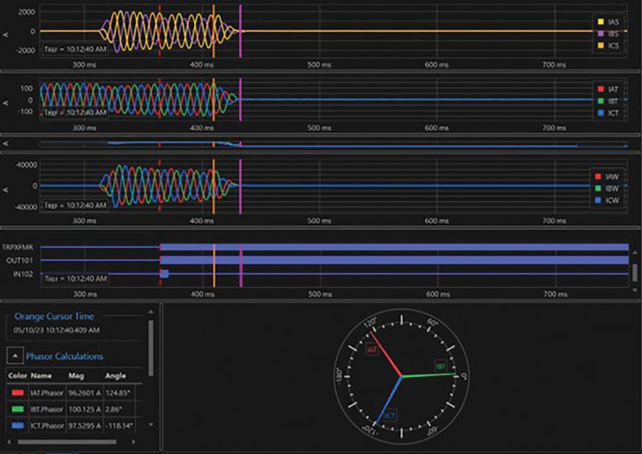
The short assertion time and the fact that the SPR did not assert during the subsequent re-energizations of the GSU is explained by SPR chatter due to the extreme forces in the GSU while the large fault current magnitude current was flowing.
This is a known behavior of SPR relays for high-magnitude current through faults. The dissolved gas analysis (DGA) indicated a high-energy electrical discharge within the transformer. This high gas level was determined to have been generated by internal faults on the low-voltage winding serving the CTG.
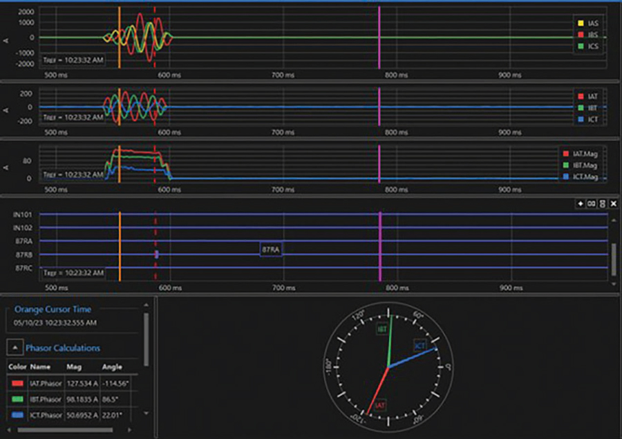
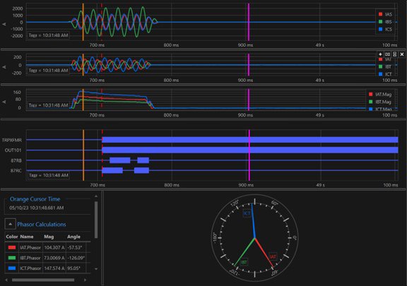
Figure 2 and Figure 3 are for the second and third main GSU main protection trips, due to the 87-transformer differential protection. It can be seen that the first fault was phase-to-ground, which evolved into a phase-to-phase-to-ground fault the third time the switchyard breaker was closed.
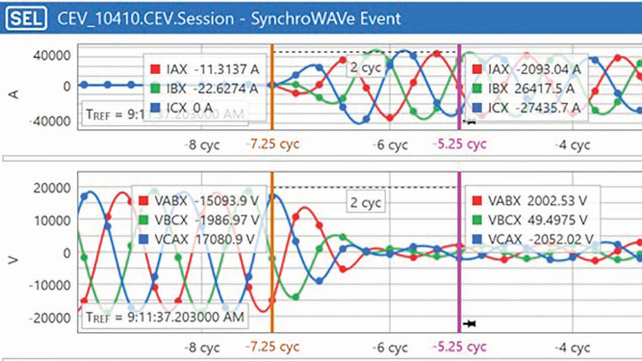
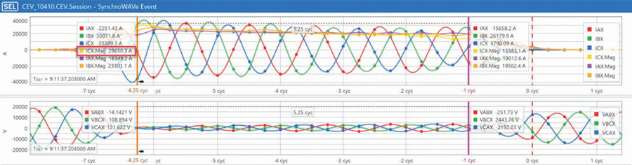
The GCB was closed when the machine was 180 degrees out of phase with the system. This was verified using oscillography from the backup generator protection. VCAX voltage goes in phase with the system in approximately two cycles. This is because the system is much stronger, and it almost instantly rotated the shaft of the generator 180 electrical degrees to force it in phase with the system (Figure 4).
The stator phase current grew extremely high in magnitude when the GCB was closed out of phase (Figure 5). The filtered current on C-phase recorded by the backup generator protection relay rose as high in magnitude as 29,650 Amps. A three-phase fault at the terminals of the CTG would produce 28,335 Amps based upon the saturated subtransient reactance (Xd”) of 0.158 per unit and a nominal current of 4,477 Amps.
Based on IEEE Std. C50.13, IEEE Standard for Cylindrical-Rotor 50 Hz and 60 Hz Synchronous Generators Rated 10 MVA and Above, generators are built to withstand a three-phase fault right at the terminals. The current magnitude produced during the out-of-phase close actually exceeded the three-phase fault current. The generator bracing was inspected to verify it was still intact.
GENERATOR STATOR GROUND FAULT PROTECTION
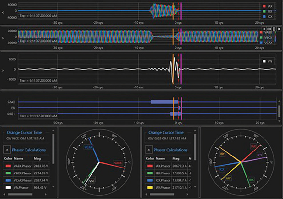
Both the main and backup generator protection relays picked up on 59N neutral overvoltage protection during the first event. The voltage at the generator neutral peaked at 1,150 V primary or 23 V secondary, which was high enough to pick up the 59N neutral overvoltage protection; however, neither timed out since the GCB quickly opened due to the main protection trip. Figure 6 shows the oscillography captured by the backup generator protection relay; the neutral voltage is the white trace.
Calculations
Following are the calculations to determine the location of the ground on the stator winding using the maximum neutral voltage measured by the backup generator protection relay:
NGT Turns Ratio = 12,000:240 (50)
|VN|max = 984 V primary
984 V/50 = 19.68 V secondary
The primary voltage (line-to-ground) impressed across the neutral resistor is as follows:
13.8 kV/1.7321 = 7,967.4 volts primary (1.7321 is the square root of three)
The secondary voltage (line-to-ground) impressed across the neutral resistor is as follows:
7967.4 volts/50 = 159.35 volts secondary (50 is the turns ratio of the grounding transformer)
The location of the ground with respect to the neutral of the stator is calculated as follows:
((19.68 V)/(159.35 V))*100% = 12.4%
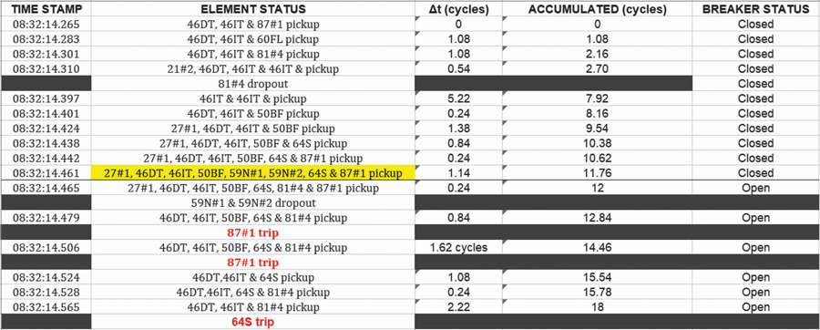
The main generator protection relay tripped on 64S 100% stator ground fault protection, which injects a 20-Hz voltage across the neutral ground resistor and is set to quickly operate (that is, several cycles versus several seconds) since this protection principle is decoupled from the 60-Hz power system. Figure 7 shows the sequence of events for the main generator protection relay.
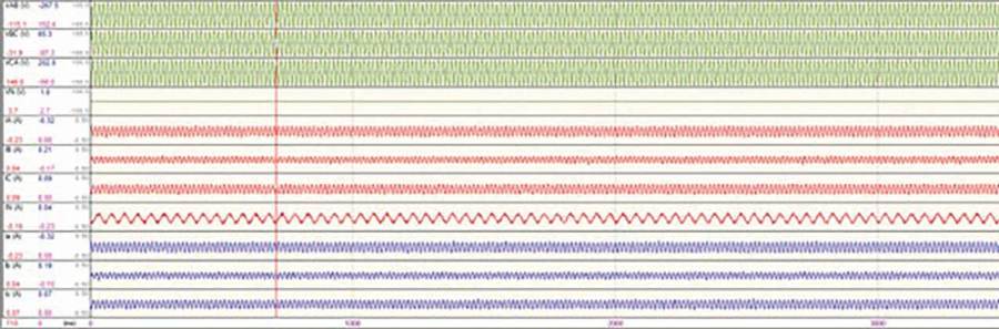
No ground was detected on the stator winding when the CTG was synched to the system again following replacement of the GSU several weeks later (Figure 8).
CONCLUSION
The protective relays operated properly as verified by the detailed analysis. An important lesson was learned: Any time a protection trip occurs, the oscillography should be reviewed first prior to attempting to re-energize the load.
Acknowledgment: The author thanks Jason Young of SEL, Inc for his significant contribution to analyzing these events.

Steve Turner is in charge of system protection for the Fossil Generation Department at Arizona Public Service Company in Phoenix. Steve worked as a consultant for two years, and held positions at Beckwith Electric Company, GEC Alstom, SEL, and Duke Energy, where he developed the first patent for double-ended fault location on overhead high-voltage transmission lines and was in charge of maintenance standards in the transmission department for protective relaying. Steve has BSEE and MSEE degrees from Virginia Tech University. Steve is an IEEE Senior Member and a member of the IEEE PSRC, and has presented at numerous conferences.