
Historically, CT connections compensated for the phase shift across a transformer when applying differential protection prior to the advent of numerical transformer protection relays. For example, a delta-wye transformer would have wye connected CTs on the delta side and delta connected CTs on the wye side. The delta connected CTs have the same connection as the transformer delta connected winding on the wye side to account for the phase shift across the transformer (for example, Dab or Dac).
INTERNAL COMPENSATION FOR TRANSFORMER PHASE SHIFT
Numerical transformer protection relays mathematically compensate for the transformer phase shift internally. Use wye connected CTs for all transformer windings when applying numerical transformer protection relays. Figure 1 shows how one numerical transformer protection relay is configured to compensate for the phase shift across a two-winding transformer with delta-wye connected windings (delta winding is connected Dab).
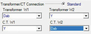
Figure 1: Mathematical Compensation for Two-Winding Delta-Wye Transformer
Here are the equations used by the numerical relay for the wye connected CTs on the delta side of the transformer (not accounting for the tap settings):
IAW1relay = IAW1CT
IBW1relay = IBW1CT
ICW1relay = ICW1CT
The values on the left side of these equations represent the currents used internal to the relay for the differential protection calculations; the values on the right side represent the current measured by the CTs. Figure 2 shows the physical connections for the Dab connected delta winding. The current flowing in the individual windings of the delta winding are IA (H1), IB (H2) and IC (H3).
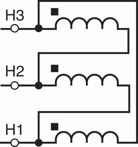
Figure 2: Dab Connected Delta Winding
Therefore:
IAW1relay = IAW1CT = IA – IB
IBW1relay = IBW1CT = IB – IC
ICW1relay = ICW1CT = IC – IA
The phase-to-phase currents measured by the relay due to the delta connected transformer winding automatically eliminate any zero-sequence current in IA, IB, and IC as demonstrated by the following symmetrical component equations for IA and IB:
IA = I1 + I2 + I0
IB = a2*I1 + a*I2 + I0
Where:
I1 = Positive-Sequence Current
I2 = Negative-Sequence Current
I0 = Zero-Sequence Current
a=1 ej120deg
IA – IB = I1 + I2 + I0 – (a2*I1 + a*I2 + I0) = (1 – a2)*I1 + (1 – a)*I2
If there is a ground source (for example, zig-zag grounding transformer) within the differential zone of a delta winding, then a zero-sequence current filter is required. This is the only time compensation is required for the current measured on the delta side of the transformer. This is a special case, however, and outside the scope of this article.
Here are the equations used by the numerical relay for the wye connected CTs on the wye side of the transformer (again not accounting for the tap settings):
IAW2relay = (IAW2CT – IBW2CT)/√3
IBW2relay = (IBW2CT – ICW2CT)/√3
ICW2relay = (ICW2CT – IAW2CT)/√3
These equations are divided by the square root of 3 to properly account for the magnitude increase due to the subtraction of two phasors of equal magnitude separated by 120 degrees (that is, assuming a balanced system).
Now the internal relay currents are properly compensated to account for the phase shift across the two-winding delta-wye transformer, which is +30 degrees for the Dab connection.
CONCLUSION
The delta winding currents should not be compensated as demonstrated above (that is, the delta winding is the reference for the relay internal current calculations). A common mistake is to assume that any winding can be chosen as the reference winding. However, then the other winding can always be rotated via internal compensation so that the calculated currents are 180 degrees out of phase for through-current conditions (such as load or faults external to the zone of differential protection). It is possible, and has happened, that if the reference winding is arbitrarily chosen, then the differential protection can misoperate.
 Steve Turner is in charge of system protection for the Fossil Generation Department at Arizona Public Service Company in Phoenix. Steve worked as a consultant for two years, and held positions at Beckwith Electric Company, GEC Alstom, SEL, and Duke Energy, where he developed the first patent for double-ended fault location on overhead high-voltage transmission lines and was in charge of maintenance standards in the transmission department for protective relaying. Steve has BSEE and MSEE degrees from Virginia Tech University. Steve is an IEEE Senior Member and a member of the IEEE PSRC, and has presented at numerous conferences.