
Although it can readily be overlooked, an important and fundamental consideration in any electrical application is safety, and one of the most effective tools in the application of safety is redundancy. If one safeguard fails, there’s another right there to act as a safety net. There’s hardly a greater necessity for redundant safety than in a substation, where arcing could otherwise electrocute an unprotected worker through many feet of nothing but air. Fortunately, industry-standard safety practices and construction preclude this.
Key elements in substation safety include maintaining safe step and touch potentials. Much of the dialogue in electrical testing and measurement deals with steady-state conditions. However, fault clearance can be dynamic in the extreme and so must be considered and effectively addressed. The typical measurement of resistance of a grounding electrode, in this instance a substation grid, is made to remote earth. This essentially means to a distance beyond which there is no further appreciable increase in resistance. The expanse of the earth, relative to the point of grounding, has become so vast that current can spread out with no additional resistance.
But what about the time it takes for fault current to reach remote earth? This may be milliseconds, but that can be all it takes to be lethal for a human in the path. Hence, additional factors must be considered and measures must be taken. This brings into account the concept of ground potential rise (GPR), defined by IEEE as:
The maximum electrical potential that a ground electrode may attain relative to a distant grounding point assumed to be at the potential of remote earth.
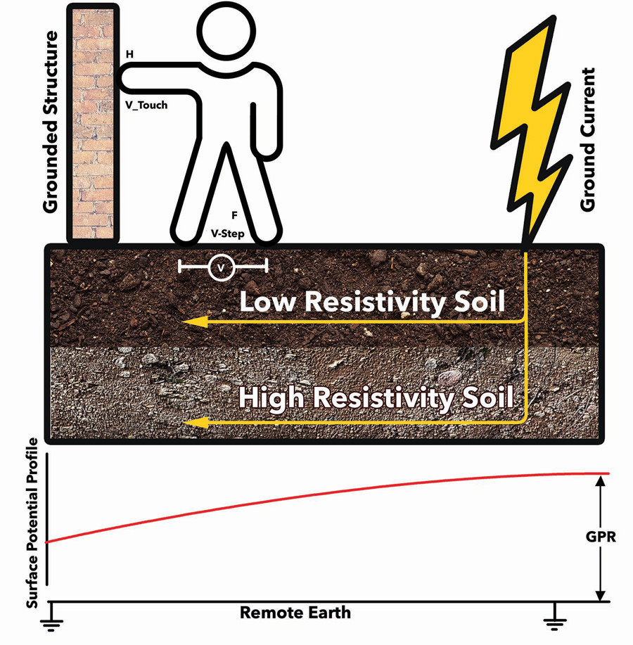
Figure 1: Low step and touch potentials protect personnel from fault currents.
This GPR voltage is equal to the maximum grid current multiplied by the grid resistance. Put simply, how can it be assured that GPR won’t kill someone on its path to remote earth? This safety measure can be maximized by limiting step and touch potentials, and an effective means of doing that is through a crushed rock substrate.
Step potential is the voltage that some poor person walking inside or past a substation could experience between his or her feet during a fault clearance situation. By convention, it is taken to be 1 meter or 3.3 feet — the accepted average length of an adult human stride. Current could be caused to flow from one foot through the body to the other foot. IEEE Standard 80 defines this as:
The difference in surface potential that could be experienced by a person bridging a distance of 1 m with the feet without contacting any grounded object.
Touch potential is similarly defined as:
The potential difference between the ground potential rise (GPR) of a ground grid or system and the surface potential at the point where a person could be standing while at the same time having a hand in contact with a grounded structure.
During a fault condition, remote earth is considered to be at 0 V, and a person standing on the substation surface will attain an elevated potential. When this person touches a grounded object (at 0 V), a shock hazard exists.
Body current drawn by touch voltage is given by:
Ib = (VTH)/ (ZTH + RB) (a)
IEEE defines conservative formulas for ZTH:
- ZTH = RF/2 for a touch voltage circuit, 2RF for a step voltage circuit
- Ib = body current
- ZTH = Thevenin impedance of the system from points H through F
- VTH = Thevenin voltage between terminals H and F when a person is not present
- RB = resistance of the human body (generally 1000 Ω)
- RF = ground resistance of one foot (Ω)
Crushed Rock Benefits
Equation [a] shows that the only parameter that can be controlled is ZTH, which is directly related to RF. It can be seen that anything that increases RF thereby decreases body current and hence provides a means of insuring personnel safety. A thin layer of crushed stone or gravel spread over the substation surface substantially increases RF, the resistance between surface soil and a person’s feet. Crushed stone has higher resistivity than surface soil, and so the potentially dangerous ground current remains confined to surface soil and isolated from a worker’s or passerby’s feet. There will be very little current in the crushed rock; hence, surface voltage (step and touch potentials) will be negligible. For purposes of standardization, a common surface material is #57 crushed granite. This includes stones commonly in the range of ¾ to 1 inch. Much larger stones can simply pose a hazard to walking.
A layer of crushed stone has additional benefits. The spacing of buried ground grid conductors can sometimes be increased, thus saving copper and expense while still meeting step and touch criteria, and surface materials retard the evaporation of moisture from the top layer of soil. The resistivity of the rock itself depends on numerous factors that can be taken into consideration. These include size and moisture content of the stone, types of material available locally, and whether the stone has been washed to remove fine material that can make it more conductive. Wetness promotes conductivity, therefore lowering resistivity, so it is desirable for the stone to dry as quickly as possible after a rain. Washed stone dries more quickly. The nature of naturally acquired wetness, i.e. rainwater versus sea spray, can also be a factor. Salt spray, for instance, promotes electrical conductivity. The resistivity of the rock itself should be measured and considered. This can be done with a four-terminal ground tester in a Miller box. Typical values of washed granite are 1.5 x 10⁶ Ω when dry and 5,000 Ω wet. IEEE 80 provides typical values for various types of surface materials commonly available in different regions of the United States.

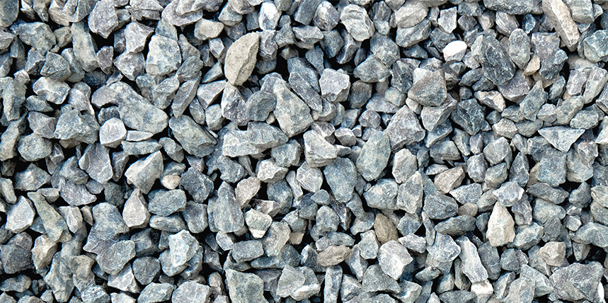
Figure 2: Soil commonly consists of layers of different composition at varying depths.
Resistivity measurement is integral to the safe and proper installation of crushed rock layers. In most cases, it is reasonable to expect surface soil to have a notably lower resistivity than the crushed rock, and everything will function as expected. However, if the opposite is the case, ground current will flow in the crushed rock and render its installation ineffective. This reversal can be dramatic, because the current is now confined to the relatively thin installed layer, making surface potential an even greater hazard than in the deeper layer of natural soil below, where current has more room to travel.
This makes understanding and practicing resistivity measurement indispensable when installing and maintaining a protective rock layer. The Wenner Method is the most widely used and can be used to note changes in resistivity with different soil types at various depths. These measurements are carried out to different depths by varying test probe spacing. Carrying out vertical prospecting in this manner is a good, redundant safety measure to ensure the soil will carry the full fault current beneath the rock layer and safely isolated from substation workers or others in the vicinity.
Top 10 Reasons to Lay Gravel/Stone in a Switchyard
- Reduce step and touch potentials
- Prevent accumulation of spilled oil
- Prevent accumulation of water
- Retain moisture in ground
- Eliminate weeds and grass
- Protect against snakes, lizards, and rats
- Reduce earthquake vibration
- Reduce vibration in transformer core
- Absorb radiated heat
- Improve working conditions
Maintenance
Once the rock layer has been installed, the job is not finished. In a more general sense, there is a widespread problem in safe grounding: Out of sight, out of mind. Grounding systems — because they are not so visibly active as lighting, machinery, computers, transformers, and so on — are easily overlooked when it comes to routine preventive/predictive maintenance. Once the layer of stone is laid, it doesn’t seem terribly remiss to consider the job done.
But don’t. Maintenance is in order, just as anywhere else in the electrical facility. Watch for weed and plant growth, which indicates a shallow or weak spot in the otherwise uniform thickness of the protective layer. Step and touch potentials could be higher in that area than design allows and pose a threat. Weed killers are commonly used, but be careful not to corrode conductors. Over time, the voids between stones can be filled in by dust settling from the atmosphere or by fine soil working its way toward the surface. This process replaces the air — a good insulator — between stones with more conductive solid material and thereby compromises the effectiveness of the protection. Additional layers of rock mitigate natural settlement.
Conclusion
A layer of crushed rock could be easily taken for granted, but it provides redundant protection against ground potential rise that could take a person’s life.
References
Voltage Disturbance Power Engineering Study Resource. Substation Grounding: Role of Crushed Rock. Accessed at Substation Grounding: Role of Crushed Rock – Voltage Disturbance (voltage-disturbance.com).
Institute of Electrical and Electronics Engineers. IEEE Std 80-2013, IEEE Guide for Safety in AC Substation Grounding.
Power System Simulation. Top 10 Reasons to lay gravel/Stones in Switchyard | Gravel/Stones laid/used in Substation Switchyard. YouTube. May 13, 2020.
 Jeffrey R. Jowett is a Senior Applications Engineer for Megger in Valley Forge, Pennsylvania, serving the manufacturing lines of Biddle, Megger, and Multi-Amp for electrical test and measurement instrumentation. He holds a BS in biology and chemistry from Ursinus College. He was employed for 22 years with James G. Biddle Co., which became Biddle Instruments and is now Megger.