
The fundamental principles of electrical ground testing were laid down in the early 20th century, with much of the pioneering work done by Frank Wenner of the U.S. Geological Survey. The most basic and widely used method for measuring soil resistivity bears his name. These principles still underlie ground testing into the present century, but many improvements have been made in the instrumentation, procedures, ease, and reliability of testing.
TESTING
It is helpful to understand what is being tested. Among other duties, the grounding electrode must successfully dissipate fault currents and noise into the surrounding earth. But what are we measuring? A resistance relationship exists with the surrounding earth, and this must be kept as low as possible by installing and maintaining adequate contact with the surrounding soil. The only prevailing standard is NFPA 70, National Electrical Code (NEC), which specifies a resistance of 25 Ω or less for a single rod. This is a forgiving standard, concerned only with safety for shock and fire prevention.
Performance, on the other hand, should be augmented by lower ground resistances. For industrial and commercial facilities, the maximum should be 10 Ω; for best protection, 5 Ω. Some particularly demanding environments, such as substation and computer room grounding, call for even lower resistances — 1.5 or 1 Ω. So far, so good, but we still have the question of what we are measuring here. A typical resistance test involves a discrete item, a length of wire, a welded bond, or similar. However, in this case, we’ve buried a critical component of the electrical system in the soil.
A common practice — and incorrect — is to run the supplied lead set that came with the ground tester out to the maximum length, take a reading, and pack up. This may work, but it’s pure luck, and no one knows the difference…until a fault occurs. A check of the literature shows that the measurement must be made to what is commonly termed “remote earth.” This means a distant point beyond which no additional resistance occurs. In theory, the entire planet forms the other end of the test circuit.
If you consider a simple resistance test as being between Point A and Point B — say, a wire from a light switch to a lamp — then in a ground test, Point A is the electrode and Point B is theoretically Planet Earth. Fortunately for all concerned, a measurable volume of earth around the electrode determines its resistance, beyond which the expanse of earth is so vast that it exerts no more than an immeasurably tiny amount of additional resistance and can be discounted.
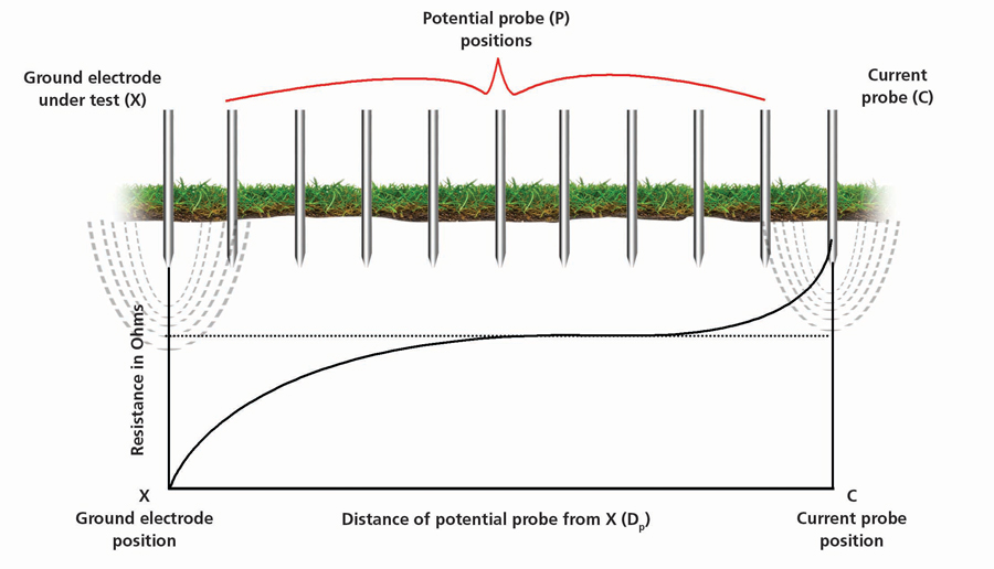
It is helpful to remember that ground currents spread out radially, not in a straight line as in circuitry. The point of no additional resistance is what is meant by remote earth, and it can be a matter of feet or miles, depending on local soil and other variables. The familiar fall of potential graph…not discussed here…if done correctly, unerringly shows the resistance to remote earth (Figure 1).
CLAMP-ON TECHNOLOGY
In the last decade of the 20th century, clamp-on technology proliferated. A clamp-on measuring instrument does not require direct contact with the item under test (IUT), such as by alligator clips. Rather, the instrument makes its measurement by sensing the electrical field generated by an AC current flowing in the IUT.
Clamp-on multimeters appeared first. These were a revelation! Measuring current by direct contact with a digital multimeter (DMM) is difficult and risky. It was generally the most demanding part of operating a multimeter. With clamp-on technology, it became a safe operation requiring only seconds to perform and was completely accurate.
But clamp-on ground testers were a quantum leap because they require two circuits and two windings: current and voltage. They appeared on the market circa 1990 but for a decade, inadequate shielding and problems with jaw alignment made readings unreliable. Some industries banned their use. But around the turn of the century, second-generation technology made an accurate and reliable clamp-on instrument possible. This was a boon to ground maintenance programs because traditional ground testing is time-consuming and labor-intensive, whereas a clamp-on takes only seconds.
LIMITATIONS
However, there are serious limitations that must be considered. Clamp-ons cannot be used for commission testing. Since the operator is not stringing leads, the tester is operating on its own. One winding establishes a test current through the clamped electrode, which then finds its path back to the jaws via the grounded utility neutral. The second winding then senses the voltage drop caused by resistance and the tester calculates the result. If the IUT has not yet been connected to the utility, no return path exists and no measurement can be made, hence no commissioning tests.
Second, the only thing the operator can control is where to place the clamp. There are no leads or probes, and the tester operates on its own. It is generally presumed that the utility return is far enough away to provide a reasonably good volume of soil for the test current to travel through. But this is conjecture and has an element of good fortune. Large systems with multiple connections, like switchyards, are not amenable because multiple parallel paths exist where the test current can simply circulate through metal and provide a comfortably low but false reading.
A clamp-on can provide valuable information, but its measurements cannot be rigorously proofed as can be done with a standard tester and fall of potential graphing. It is paramount to know these limitations, use the clamp-on where it is reliable and saves time, and go to traditional fall of potential procedures with leads and probes where maximum accuracy and reliability are essential.
IMPROVEMENTS
Auto terminal selection helps the operator by speeding the test and reducing the opportunity for errors. With a simple instrument like a DMM, terminal selection is a no-brainer; you just hook two terminals across the IUT. But a ground tester’s four terminals require judicious engagement. All four are a must for measuring soil resistivity but the operator can choose between three (quicker test time) or four (more accurate measurement) when doing a resistance test.
Even just two can be used for the quick and popular but less reliable “dead earth” test. Traditionally, shunt bars were used to connect terminals, with paper clips or pieces of wire often having to make do. This took time and was subject to error. Now, testers provide all these options on a clearly delineated selector switch. No more forgetting to disconnect the paper clip and then wondering why the readings are so high.
Noise suppression is vastly improved by modern circuitry. No more guessing the middle of the pointer swing, or worse, accepting a noise-influenced reading as accurate. To cope with noise, ground testers have traditionally employed a square wave of a distinct frequency, so the measurement circuitry could recognize its own signal. In poor environments, the signal frequency could still be overwhelmed.
With the march of progress, better and better means of coping emerged. Filters were added that averaged the swings — a more accurate interpretation than the operator’s judgment. The filters could be disengaged for speed of testing in quiet environments. Next, multiple selections became available, along with warning indicators. Too much destabilization of the readings? Try another frequency. This capability was steadily improved with micro-circuitry until it is now almost infinite.
As an example, a typical value is 10 to 200 Hz, selectable in half-Hz intervals. If the operator can’t find a quiet zone, none exists! Pull up the leads and go in another direction. Brand-new or borrowed personnel need not be defeated by this option. All they have to do is select it, and the tester automatically searches.
Indicators now advise the operator of problems, like noise (Figure 2),voltage on the IUT, and even missed instructions. Clamp functions are now built into full-function testers so that a well-trained operator can select the best test method, terminal operation for accuracy, or clamp-on for speed. Built-in clamp-on testing is accomplished by two separate clamps so that the operator can also recognize current traveling on the ground rod or grounding conductor. This provides vital information as it indicates problems like load imbalances in the electrical system.
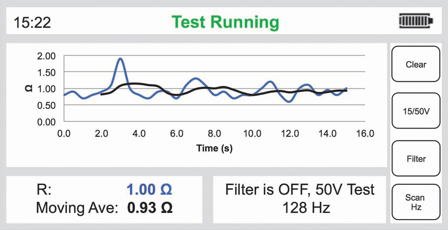
Ground tests are thought of as static measurements. Take a reading and that’s the resistance of the IUT. This is generally true, but noise interference can add a dynamic element to the testing. Modern testers can cope with this by engaging active color graphics that plot measurements over time, along with background noise, providing the operator with a visual record that can be printed and stored. No more worrying that you may have selected an influenced value not representative of the IUT.
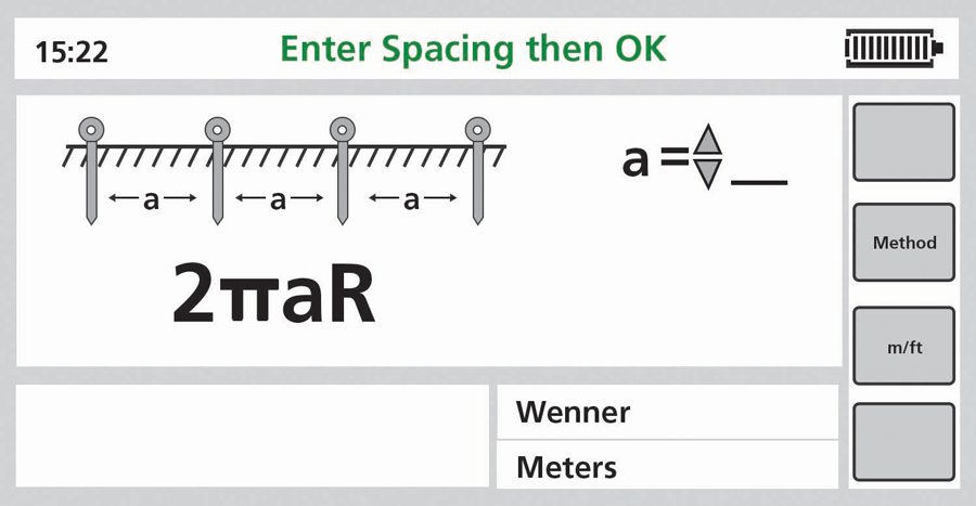
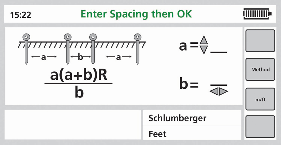
Digital displays can now achieve a resolution of 1 mΩ. For ground testing, this is massive overkill; however, for soil resistivity, where the measurement is volumetric in Ohm-centimeters, the extra digit can significantly improve the calculation. Moreover, modern testers now perform the calculation, selectable between the Wenner (Figure 3a) or Schlumberger (Figure 3b) methods, saving the operator time and possible error.
Finally, the most tedious part of ground testing — incessant walking back and forth — has been significantly improved by testers with remote control and GPS features. The operator need only walk the line once, sending a signal back to the tester to record the value of each new spike position. The fall of potential (FOP) graph is drawn on the display, enabling on-the-spot evaluation and determination. Global positioning has been incorporated into advanced testers so that test reports can be printed with maximum accuracy and clarity.
CONCLUSION
Old testers from the mid-20th century, once calibrated, can still provide reliable results. That’s what they were made to do. But modern testers add many features and functionalities that speed the test, increase accuracy and reliability, and make one of the most demanding of all electrical tests notably less so.

Jeffrey R. Jowett is a Senior Applications Engineer for Megger in Valley Forge, Pennsylvania, serving the manufacturing lines of Biddle, Megger, and Multi-Amp for electrical test and measurement instrumentation. He holds a BS in biology and chemistry from Ursinus College. He was employed for 22 years with James G. Biddle Co., which became Biddle Instruments and is now Megger.