

Most utilities in the United States are required to comply with North American Electric Reliability Corporation (NERC) regulations. Some of these regulations require utilities to develop performance-based, condition-based, or time-based maintenance programs, and the execution of these programs is what opens a window of opportunity for testing companies to offer services oriented to help utilities achieve their maintenance testing needs.
This article provides a starting point for understanding the NERC standards structure and focuses on a specific standard to show examples of the services that can be offered and to what extent.
NERC BASICS AND STANDARDS STRUCTURE
The Electric Reliability Organization (ERO) is a regulatory agency comprised of NERC and the six Regional Entities. It guarantees the reduction of reliability and security risks of the electric grid of the continental United States, Canada, and the northern part of Baja California, Mexico.
The Electric Reliability Organization for North America (NERC) is subject to oversight by the Federal Energy Regulatory Commission (FERC) and governmental authorities in Canada. NERC’s jurisdiction includes users, owners, and operators of the bulk power system, which serves nearly 400 million people. NERC develops reliability standards and enforces them on users, owners, and operators of the bulk power system (BPS). It also performs assessments of seasonal and long-term reliability, monitors the BPS through system awareness, and provides training and certification to utility personnel.
NERC includes two categories of enforceable standards: continent-wide and regional. These are labeled with up to seven identifiers. The four main identifiers are:
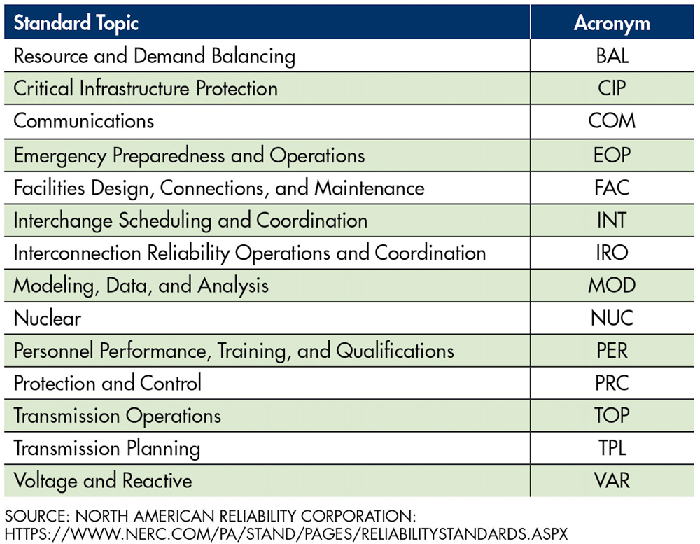
- Standard topic: a three-letter acronym indicating the family or general topic of the standard
- Standard number: a three-digit numeral indicating the document number within the standard family
- Version number: a one-digit numeral indicating the version of the document
- Regional acronym: a three- or four-letter acronym identifying the region in which the regional document applies
Examples of standard numbers include BAL-001-1, CIP-004-3a, COM-001-1.1, FAC-501-WECC-1, and PRC-004-2.1(i)a. Table 1 lists the 14 standard topics covered by NERC. Figure 1 and Table 2 show the six regional entities.

SOURCE: NORTH AMERICAN ELECTRIC RELIABILITY CORPORATION — PRINTED WITH PERMISSION

NERC standards include approximately 100 subject to mandatory enforcement. All are accessible through One Stop Shop, which provides a direct link to each standard as well as a consolidated and sortable listing of the standard number and title, status, purpose, different important dates, implementation plan, and others.
This listing is a good starting point for identifying standards suitable for design and implementation services to offer. For example, searching for “maintenance” identifies one standard related to facilities design, connections, and maintenance (FAC) and five standards related to protection and control (PRC) (Table 3). Note: These standards are mandatory, subject to enforcement. Details are available at https://www.nerc.com/pa/comp/Pages/Reliability-Standard-Audit-Worksheets-(RSAWs).aspx.

This paper focuses on PRC-005-6 to explain the structure and requirements of a standard in further detail and suggests the specific testing services to offer.
DETERMINING SERVICES TO OFFER FROM ONE STANDARD
The standards are structured very similarly. The three or four main sections are listed below with a brief description and comments related to the scope of this paper.
Introduction
The introduction contains the title, purpose, and applicability.
Purpose is the first section to look at to determine whether it is suitable to offer services related to the standard. The purpose of PRC-005-6 is:
…to document and implement programs for the maintenance of all Protection Systems, Automatic Reclosing, and Sudden Pressure Relaying affecting the reliability of the Bulk Electric System (BES) so that they are kept in working order.
Applicability lists the entities and any additional specific details of the target customers for the services to provide. The applicability section of PRC-005-6 lists the transmission owner, generator owner, and distribution owner, as well as seven specific facilities. For example:
…Protection Systems and Sudden Pressure Relaying that are installed for the purpose of detecting Faults on BES Elements (lines, buses, transformers, etc.).
Requirements and Measures
In this section, specific requisites are listed. Each one has a violation risk factor (VRF) and a time horizon (TH), which are two of several elements used to determine the sanction when the corresponding requirement is violated.
- Risk factor determines the impact on the reliability of the system by violating a specific requirement. It can be low, medium, or high.
- Time horizon is used as a factor in determining the size of a penalty. There are five time horizons: long-term planning, operations planning, same-day operations, real-time operations, and operations assessment.
If a requirement is violated and its time horizon is real-time operations, the penalty will be higher than it would be for violating a requirement that could be addressed over an extended period. Each requirement is complemented by a measure that elaborates on what is expected for each requirement.
PRC-005-6 has four requirements. For the facilities identified in the introduction section, the first one indicates:
Each Transmission Owner, Generator Owner, and Distribution Provider shall establish a Protection System Maintenance Program (PSMP) for its Protection Systems, Automatic Reclosing, and Sudden Pressure Relaying.
Further details of the requirement indicate that the PSMP should identify which maintenance method (time-based, performance-based, or a combination) is used for each protection system. It also indicates that all batteries associated with the protection system’s DC supply shall be maintained following a time-based program described in the standard. Requirements 2, 3, and 4 are specific to the selected maintenance method.
In other words, Requirement 1 dictates that there shall be a maintenance program for the protection system, and it leaves the freedom to select from a performance-based or time-based method for the protection system. However, for the batteries associated with the protection system, Requirement 1 dictates that a specific time-based program shall be used.
The requirements and measures section is the part of the standard to look for when determining which services to offer. For example, from Requirement 1 of PRC-005-6, utilities subject to NERC compliance must test their relays and their batteries. For relays, despite the freedom and guidelines from the standard, it has been noticed that most utilities still want to do element testing when new settings are implemented or various elements are made to trip for SCADA checkout. For batteries, the requirements and measures section specifically states what needs to be done at a minimum.
The following sections cover a simplified approach to ensure NERC guidelines are met while still having the ability to perform element testing when required for relays and the main tests to offer for batteries.
Compliance
This section defines the evidence-retention periods so utilities can demonstrate compliance. As part of the evidence, the utility must keep the current PSMP and the maintenance evidence for each asset. This implies that the utility keeps an asset management system, and all maintenance activities must be logged in their system. In this case, a service company providing maintenance services must provide test reports per their system requirements.
The compliance section also contains the Table of Compliance Elements, where each requirement has a different violation severity level (VSL). The VSL indicates the degree to which a requirement was violated and is a third element used to determine the penalty in case of a violation.
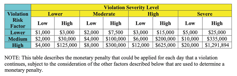
NERC uses the information in Figure 2 to determine the initial sanction by considering the violation risk factor (VRF) of the violated requirement and the VSL assessed for the violation. Other factors such as entity size, assessed risk, violation duration, and violation of the time horizon are considered for the final monetary penalty amount.
SOURCE: NORTH AMERICAN ELECTRIC RELIABILITY CORPORATION — REPRINTED WITH PERMISSION
For example, since PRC-005 Requirement 1 has a medium VRF, the daily penalty can range from $2,000 to $335,000 depending on the VSL. This demonstrates how important it is for a utility to comply with the standards.
SIMPLIFIED RELAY TESTING AND RECOMMENDED BATTERY SERVICES FOR NERC PRC-005-6 COMPLIANCE
From the maintenance and testing opportunities perspective, PRC-005-6 can be broken down into the parts listed below. Each part contains the suggested simplified relay and battery testing recommended as services to provide:
Protective Relays and Components of Control Systems that Respond to Measured Electrical Quantities and Provide Protective Functions
The tables in PRC-005-6 use words like “verify,” “test,” and “calibrate.” It is important to understand the meaning of these words. The standard provides a glossary of terms with key definitions:
- Verify: Determine that the component is functioning correctly.
- Monitor: Observe the routine in‐service operation of the component.
- Test: Apply signals to a component to observe functional performance or output behavior or to diagnose problems.
- Inspect: Examine for signs of component failure, reduced performance, or degradation.
- Calibrate: Adjust the operating threshold or measurement accuracy of a measuring element to meet the intended performance requirement.
For purposes of readability, flow, and space, only one NERC PRC-005-6 table is included in this paper. All other tables referred to from the standard can be consulted in the actual document from NERC: https://www.nerc.com/pa/Stand/Reliability%20Standards/PRC-005-6.pdf.
For relay testing, PRC-005-6 Table 1-1 (transcribed as Table 4 in this paper) provides time-based testing requirements defined by the type of relay and the amount of monitoring provided.

To determine a simplified maintenance testing approach, it is important to note the following:
For non-microprocessor relays, the maximum maintenance interval is six years. This is the maximum allowable time, and many manufacturers of electro-mechanical relays recommend more frequent calibration to ensure the accuracy of the relay.
The table requires testing and calibration of non-microprocessor-based relays.
If the relay is microprocessor-based and not monitored, it must be tested every six years.
The table requires verification of the operation of relay inputs and outputs and the measurement of power system input values. This is related to making sure the analog-to-digital (A/D) converters measure proper voltage or current and phase angle.
Since the requirement for microprocessor-based relays is to verify, full functional testing is not required for routine maintenance. The minimum requirements are:
- Verify that the settings are as specified. It is particularly important to have a setting document to compare to. As a NETA testing company, it is common to be asked just to test the relay as it was found. NERC specifically calls out to verify that the settings are correct. If the customer does not have a document with settings, it is recommended to compile a document with all relay settings and have the customer’s engineering department review and verify it so there will be a settings document going forward. Compiling this document is a service that can be offered.
- Verify operation of the relay inputs and outputs that are essential to proper functioning of the protection system. This statement requires you to test the functionality of all inputs and outputs that are in use for protection. Preferably, this is done by operating the element that activates that output. For example, if the relay has reverse power, you would create a reverse-power condition and make that output operate and trip intended devices. The way the standard is written, the user must make the output operate (which could be a force output on command) and verify that it initiates the proper trip circuit.
- Verify acceptable measurement of power system input values. This statement simply means to test all A/D converters in the relay. These are typically the voltage and current inputs. Most modern microprocessor relays have several reading ranges. For example, the relay may have a 0- to 5-amp scale for accurate low power readings but may have a larger 20- or 30-amp scale for high fault-type readings. The standard only requires you to check the readings at one level, but as a best practice, we recommend checking at multiple levels based on the maximum voltage or current the relay could see to ensure all scales are accurately reading.
Communications Systems Necessary for Correct Operation of Protective Functions
Communication systems are becoming more prevalent in protective relay systems, and the standard requires verification of any protection communications for proper operation. These can include:
- A fiber connection between substations for line differential
- Communication connection between subs for the transfer trip
- Any communication connections to monitor relay status
PRC-005-6 Table 1-2 provides information on when and what items must be verified. For unmonitored systems, you must verify that all inputs and outputs operate properly, such as when two relays (one on each end) are used for line protection with distance elements as shown in Figure 3. This is a typical permissive underreach transfer trip (PUTT). In this case, if either relay sees a distance fault, both ends trip, and the trip is transferred from one end to the other via communication equipment. This equipment must be verified as part of NERC PRC-005-6 compliance.

One of the requirements of the standard is to verify all input and output operations. Most companies perform end-to-end testing to verify that logic and inputs work properly. This also verifies the operation of the communication system. It is important to document that the communication connection was verified as part of the test.
However, the standard also requires verifying “that the communication system meets performance criteria pertinent to the communications technology applied (e.g., signal level, reflected power, or data error rate).” Most relay manufacturers have some type of communication error report built into the relay. This report should be reviewed and attached as part of the compliance documentation.
Voltage and Current Sensing Devices Providing Inputs Necessary for the Correct Operation of Protective Functions
Voltage transformers (VTs) and current transformers (CTs) play an important part in system protection. Traditionally, CTs and PTs are fully tested during commissioning and then tested periodically to ensure proper operation. NERC PRC-005-6 Table 1-3 requires devices that do not have continuous monitoring to be verified every 12 months.
Continuous monitoring of PT and CT circuits is not common. To have continuous monitoring, you would need a second set of PTs or CTs on the same circuit as the PT or CT supplying the relay current or voltage. The second set would need to be continuously compared to verify they have the same current or voltage. This is done on some PTs for generation, but it is uncommon for most voltage and current transformers.
Therefore, for most protective relay circuits, voltage and current transformers must be verified every 12 months. Verification requires checking the CT or PT values compared to known readings. This can be done in several ways:
- Ratio test the device and ensure proper readings. The wiring should also be checked to ensure the proper voltage or current appears correctly at the relay.
- Compare to readings from the same bus. For example, if the bus voltage and line voltage are the same (because the incoming breaker is closed), then the values of the bus voltage reading can be compared to the value of the incoming voltage. If equal, then the voltages have been verified.
- All PT and CT readings must be verified. This can be more difficult on a ground PT or CT where there typically is no current. In those cases, ratio testing may be the best means.
- The maintenance program should include a test of CTs and PTs or verification of readings.
Station DC Supply Associated with Protective Functions
For battery testing, PRC-005-6 mandates:
All batteries associated with the station DC supply Component Type of a Protection System shall be included in a time-based program as described in Table 1-4 and Table 3.
Table 1-4 is divided into six parts:
- Table 1-4(a) is for vented lead-acid (VLA) batteries.
- Table 1-4(b) is for valve-regulated lead-acid batteries (VRLA).
- Table 1-4(c) is for nickel-cadmium batteries (NiCad).
- Table 1-4(d) is for protection systems using non-battery-based energy storage.
- Table 1-4(e) is for protection systems for non-BES interrupting devices as part of a remedial action scheme (RAS) and others.
- Table 1-4(f) contains exclusions for protection systems with DC supply monitoring devices and systems.
Out of all the 1-4 tables, Table 1, Table 2, and Table 3 are the main ones to consider when deciding which services to provide for battery maintenance. The maximum maintenance intervals are defined as 4, 6, and 18 calendar months and 3 or 6 years, depending on the type of battery. Each maintenance interval in the range of calendar months includes a list of verifications and inspections for each battery that can easily be offered by a service company:
- Verify:
- Station DC supply voltage
- Float voltage of battery charger
- Battery continuity
- Battery terminal connection resistance
- Battery intercell connection resistance
- Inspect:
- Electrolyte levels
- For unintentional grounds
- Cell condition visually or by employing ohmic testing
- Physical condition of the battery rack
The 6-month, 18-month, 3-year, and 6-year maintenance intervals, depending on the battery, relate to verifying that the battery can perform as manufactured. Two options are offered:
Evaluate measurements that are indicative of the battery performance. Ohmic measurement is the most comprehensive and has a higher trending capability for this simplified method.
Conduct a performance or modified performance capacity test of the battery string.
This leaves the ohmic testing and the performance capacity test as the main tests to perform on a battery. Each utility decides which to use depending on what they consider more practical and beneficial based on their system and resources. The ohmic testing involves fewer logistics but requires frequent visits (every 6 or 18 months) to the battery, but it does not provide the most accurate assessment. The capacity test provides the most accurate assessment of the state of health (SOH) of the battery and requires fewer visits (every 3 or 6 years) to the battery, but requires a lot of resources, time, and effort to complete. As a service company, it is critical to understand both testing methods and be able to provide them. These are the most common and high-demand tests for NERC compliance and could be the entry tool to provide other NERC compliance services to utilities.
Control Circuitry
Table 1-5 of NERC PRC-005-6 dictates that the following control circuitry must be verified: Actuators of circuit breakers, interrupting devices, mitigating devices, and electromechanical lockout devices. These elements are specifically listed and should be included in all compliance documents.
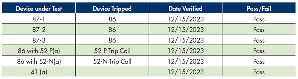
Documentation is key for compliance. Creating a table of devices in the trip circuit and documenting the verification of operation is one method. Table 5 shows an example of documentation for the simple trip circuit in Figure 4. Providing a highlighted printout of all items verified is another means to document, but saving and supplying the documentation to auditors is much more difficult.

SOURCE: TONY R. KUPHADLT. ELECTRIC POWER MEASUREMENT AND CONTROL SYSTEMS CC BY 4.0
Automatic Reclosing
Reclosing was added to PRC-005-6 per FERC Order 758. Reclosing relaying is similar to protective relaying and the functionality is often in the same relaying package previously discussed. All the reclosing requirements of PRC-005-6 are listed in Table 4-1, Table 4-2, and Table 4-3. The tables are like those for protective relays, and the same recommendations previously discussed apply.
Sudden Pressure Relaying
FERC Order 758 directed that maintenance of reclosing relays and sudden pressure relays that affect the reliable operation of the bulk power system be addressed in PRC-005-6. Sudden pressure relaying is important because it is one of the quickest devices for detecting a fault in a liquid-filled transformer. A fault causes a rapid change in gas pressure, oil pressure, or oil flow that indicates an internal fault.
There are three main types of fault pressure relays:
- Rapid gas pressure devices monitor the pressure in the space above the oil (or other liquid) and initiate tripping action for a rapid rise in gas pressure resulting from the rapid expansion of the liquid caused by a fault. The sensor is in the gas space.
- Rapid oil pressure devices monitor the pressure in the oil (or other liquid) and initiate tripping action for a rapid pressure rise caused by a fault. The sensor is in the liquid.
- Rapid oil flow devices (Buchholz) monitor the liquid flow between a transformer/reactor and its conservator. Normal liquid flow occurs continuously with ambient temperature changes and with internal heating from loading and does not operate the rapid oil flow device. However, when an internal arc occurs, a sudden expansion of liquid can be monitored as rapid liquid flow from the transformer into the conservator, resulting in actuation of the rapid oil flow device.
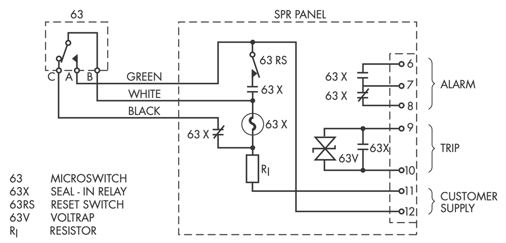
PRC005-6 Table 5 requires verifying that the pressure or flow sensing device is operational. For this, sudden pressure relays typically have a test port (Figure 5, Customer Supply), where additional pressure can be added to the relay and then quickly removed to cause the device to operate. Consult the manufacturer’s instructions for the test procedure.
SOURCE: STEVE TURNER
OTHER STANDARDS AND SERVICES TO CONSIDER
In addition to the actual testing services to offer, a service company can explore supplying training, compliance program development and management, audit support, and engineering evaluation.
In the area of engineering and consulting services, PRC-019, PRC-024, and PRC-025 are standards that generate opportunities to develop compliance studies and conduct compliance reviews and testing related to generator relay settings.
The NERC series of standards relates to generating facilities, and with the proliferation of renewable energy generating facilities such as wind and photovoltaic, many more sites and customers will need help to follow NERC standards, especially in power system studies.
Critical infrastructure protection (CIP) standards affect personnel interaction with substation assets, so it is important to review these and be prepared to comply with requirements for personnel to be able to provide services. Standard CIP-004 requires that personnel of a team with access to critical equipment must have the proper risk assessment credentials, training, and security awareness. This includes contractors and service vendors who should define and maintain a security awareness program to comply with this standard.
According to CIP-005, contracts with vendors, contractors, and consultants should include language that requires adherence to the responsible entity’s interactive remote access controls.
CONCLUSIONS
NERC standards open a wide range of business opportunities for service companies. As a service company, it is important to:
- Demonstrate understanding and sound handling of the standards and requirements.
- Prepare business cases to demonstrate the cost/benefit ratio for utilities to consider outsourcing specific compliance services.
- Understand and have the resources and develop the expertise to offer and provide the services. What is required is not new or strange to service companies, and this is where a big advantage exists.
Since documentation and evidence retention are so critical for compliance, utilities will look for an easy way to integrate the service provider’s reports into their computerized maintenance management system (CMMS). As a service provider, it is important to pick software that allows for proper maintenance data handling and can integrate with platforms such as Maximo or SAP.
Note: This paper was delivered at PowerTest24.
REFERENCES
- NERC. ERO Enterprise | Regional Entities. Available at: https://www.nerc.com/AboutNERC/keyplayers/Pages/default.aspx. Printed with permission.
- NERC. Reliability Standards. Available at: https://www.nerc.com/pa/Stand/Pages/ReliabilityStandards.aspx.
- NERC.One-Stop Shop. Accessed at:www.nerc.com/pa/Stand/AlignRep/One%20Stop%20Shop.xlsx.
- NERC PRC-005-6, Protection System, Automatic Reclosing, and Sudden Pressure Relaying Maintenance. Available at: https://www.nerc.com/pa/Stand/Reliability%20Standards/PRC-005-6.pdf.
- Tony R. Kuphaldt. Electric Power Measurement and Control Systems. Used under license CC BY 4.0. Accessed at Electric Power Measurement and Control Systems | Openverse.
- NERC.NERC Sanction Guidelines. Violation Risk Factor and Violation Severity Levels Table, p. 7. Accessed at https://www.nerc.com/AboutNERC/RulesOfProcedure/Appendix_4B_effective%2020210119.pdf#search=sanction%20guidelines. Printed with permission.
- Steve Turner. “Functional Testing for a Sudden Pressure Relay,” NETA World, Winter 2019. Available at: https://netaworldjournal.org/functional-testing-for-a-sudden-pressure-relay/. Printed with permission.
- FERC Order 758. Available at: https://www.nerc.com/pa/Stand/Pages/Project2007172ProtectionSystemMaintenanceand-TestingPhase2ReclosingRelays.aspx.

Volney Naranjo joined the Technical Support Group at Megger in 2011 as an Applications Engineer focusing on the products for transformer, low-voltage and high-voltage circuit breakers, batteries, and power quality testing. He participates in the IEEE Energy Storage and Stationary Battery committee and has published articles in conferences such as TechCon, PowerTest, TSDOS, BattCon, and EIC as well as technical magazines. Volney received his BSEE from Universidad del Valle in Cali, Colombia. After graduation, he worked in the areas of electrical design and testing and commissioning of power systems as a field engineer and project manager.

Mark Pustejovsky is the Product Manager for protective relay and high-current test equipment at Megger, where he uses his field knowledge and practical experience to develop user-focused equipment. A graduate of Texas A&M University and a NETA Level 4 Certified Senior Technician, Mark performed field testing of electrical equipment for most of his career, specializing in protective relays. He also performed engineering studies, including power quality and arc flash, and managed an engineering group while working at Shermco Industries.