
There is always room for improvement. In electrical testing, this is particularly true because of the rapid development and application of the underlying electronics. Although a job may be proceeding with maximum satisfaction, it may well be made easier, faster, more accurate, and safer.
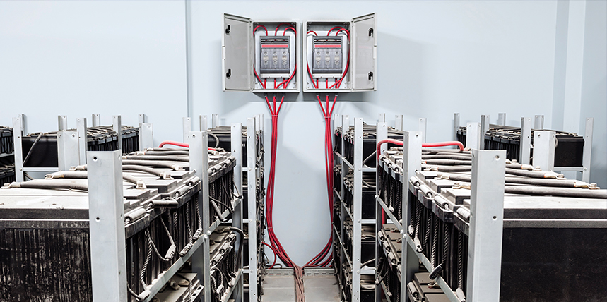
For example, standby battery banks can develop ground faults over time through leaking electrolytes, accumulation of dirt, rodent damage, water ingress, faulty installation, and other problems. Over time, the battery system can become shorted to ground and lose power. When called on-line, it can fail to deliver, and the consequences can be catastrophic: interruption of production, lost data, fire, and shock.
Battery ground-fault tracers are specifically designed to pinpoint these faults. A quality unit can remain in service for many years, and it need not be replaced merely due to age. Now — especially on particularly complex and difficult systems — recent developments in technology can address the most difficult problems and notably enhance the speed and accuracy of fault tracing.
Ungrounded battery systems typically have ground-fault monitors that tell the operator a fault has occurred, but they cannot indicate where it is, and locating it can be a tedious, time-consuming, and frustrating job. A maintenance technician can end up chasing a phantom fault all day long without success. Fortunately, technology has risen to the task.
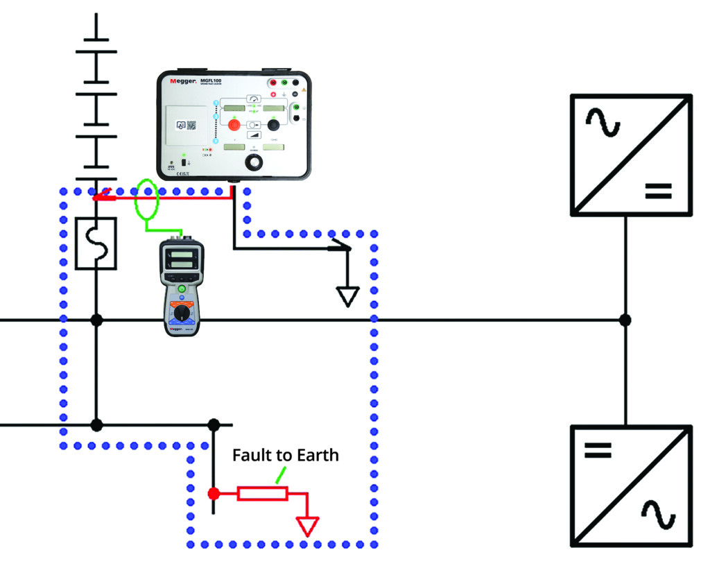
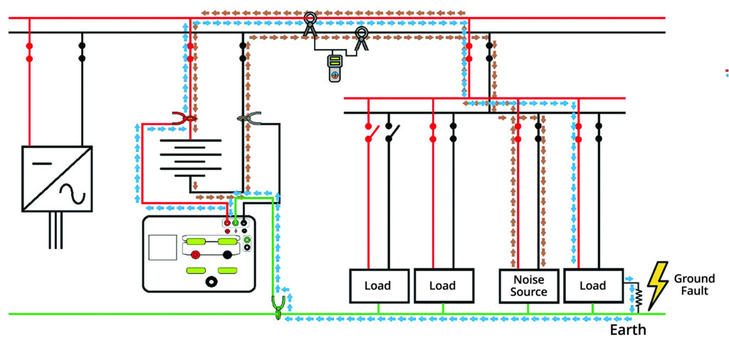
Specialized equipment is necessary to locate such faults. A transmitter applies a distinct signal that flows through the ground fault. A second piece of equipment, a receiver, is used to trace the signal (Figure 1). This is simple in concept but subject to pitfalls.
ISSUES WITH FAULT TRACING
Improvements are available to specifically address the most difficult fault-tracing problems. System noise can interfere with signal detection. Circuit capacitance can pull excessive current. A high-impedance fault may exist, or a breaker may trip. Current clamps can become magnetized and impossible to use. These can be major problems that can now be overcome.
Stray capacitance as part of cable construction will pull extraneous current that the operator might waste time following instead of the fault current. Noise from SCADA can be severe and swamp the trace signal. Water ingress breaks down insulation and produces a high-impedance fault that requires more current to trace but at the same time can dry the cable and mask the fault. An ungrounded DC system can still have direct current flow that can interfere with fault tracing. The iron core of the CT that is tracing the flow of the ground-fault current can become magnetized. The strength of this force can make it nearly impossible to physically remove the CT without actually breaking it.
SOLUTIONS
Tracing battery ground faults often requires high sensitivity to extremely small leakage currents. High permeability makes CTs more sensitive but also more susceptible to magnetization. The problem can be effectively addressed by a core made of an appropriate mu-metal compound. A mu-metal is a nickel-iron alloy containing small amounts of other elements like copper, chromium, or molybdenum. These can be precisely formulated for the best performance in a specific application. An effective formulation can produce high permeability with little magnetization.
Another technology that has proved useful is a flux gate. This works with small numbers and requires extraordinary sensitivity, hence it is relatively uncommon. A low-frequency signal in the range of 5 Hz when clamped over the current-carrying fault will become distorted. This distortion in the signal allows the current clamp to measure very-low-amplitude signals. Such CTs can be kept notably small so as to fit into the tightest spaces while following a signal. A sliding opening can be kept small in comparison to the spreading jaws of standard CTs, thus enabling clamping over wires in the tightest spaces.
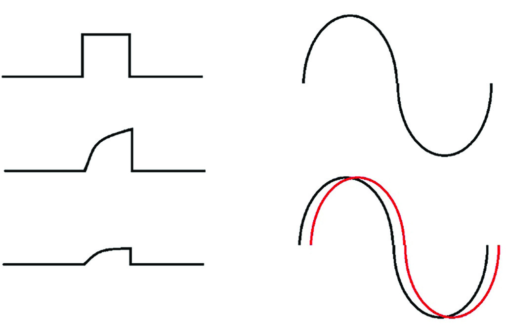
Stray capacitance is traditionally dealt with by tuning it out. The test circuit acts as a Wheatstone bridge by placing a signal 180 degrees out of phase with the fault. This works on systems with an AC injection current but can be tedious and time-consuming. Systems operating with pulse technology can be more challenging, as the pulse is dampened by capacitive charging. A remedy is to use an AC signal and measure the phase shift between voltage and current, which increases with capacitance (Figure 2). The phase angle can be measured, enabling the tester to distinguish between current drawn by the fault and that from capacitance, eliminating hours spent tracing the wrong path.
Noise is another problem because it destabilizes the tester’s readings. Noise can return on the return line and interfere with the tracing signal. However, the trace signal returns on the ground and can be used to separate the signals during tracing. Therefore, if the tracing CT can be clamped over both paths, the noise cancels (Figure 3).
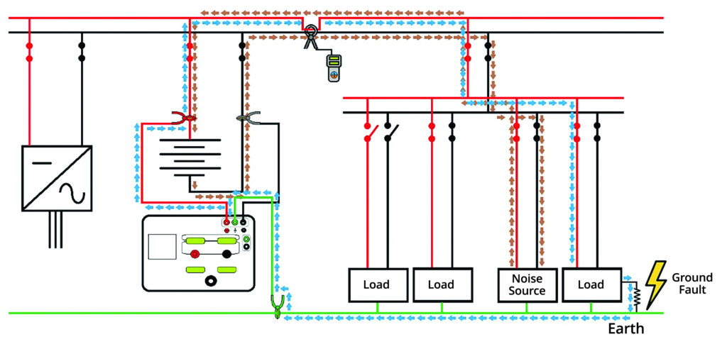
But what if the CT can’t be fitted around both paths simultaneously? Just use a second CT clamped on the return line. The CTs are in parallel, 180 degrees out of phase. Sophisticated testers will accommodate two CTs (Figure 4).
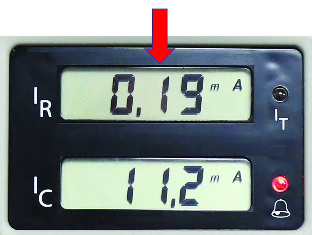
High-impedance faults are another challenge. Because impedance is high, little current is passing through the fault. Hence, tracing requires extra sensitivity. Modern test instruments can typically tolerate impedance levels on the order of 400 kΩ while still being able to sense and trace the fault. For illustration, the fault current may be on the order of 0.19 mA and orders of magnitude less than the current drawn by stray leakage capacitance. The differential could be narrowed by increasing the fault current by increasing the voltage on the transmitter.
Some instruments can increase the voltage to as much as 1,000 V, but this has attendant hazards. It increases the risk to the operator and can trip breakers. And as we’ve seen, a moisture fault can be dried out before it’s been located, only to return on the next rainy day. An effective remedy is a hi-tech test instrument that can distinguish between actual fault current and reactive current drawn by the fault while indicating both to the operator on a dual display (Figure 5).
Tripping breakers can be a nuisance consequence of fault tracing. This happens when the output voltage of the tracing instrument is turned up too high and then energized. A transient spike trips the breaker. A sophisticated instrument will enable limits to be set on voltage and current below values that will trip breakers and can be password protected.
CASE STUDIES
As an example of how tedious these unwanted grounds can be to locate, a major utility had been searching for a ground fault for two years using a standard locator. The panel was in a different room from the battery string, with a confusing plethora of circuits. All were contributing capacitive leakage that showed up as fault current on a standard tracing instrument. Distance made it impossible to use the feedback cable on the tracer, and even when the string was closer, there were still a prohibitive number of circuits. A sophisticated tracer that employs a special accessory, a capacitive pickup, was used. The pickup was placed on a return line. It measured a static field rather than current, so did not need to be moved to all circuits. The CT could now be moved to each circuit. The receiver’s dual display was now able to show the fault current as well as the leakage current with a visual display and an audible tone when on the proper circuit. The transmitter was then left on the battery string while the receiver and capacitive pickup were moved to another floor. The fault was readily traced to a pump on that floor.
Another problem case appeared in a utility substation. Using multiple instruments, a fault was traced to a battery charger. The charger was replaced but the fault persisted. Using a state-of-the-art tracer and connecting to the battery string immediately revealed a negative to-earth fault. When fault current was applied, the measurement proved totally unstable. Turning off the transmitter revealed the presence of AC on the line. Setting the locator’s receiver to the 50/60 Hz mode enabled the AC to be traced to the battery charger, where a wiring issue that caused AC to get coupled onto the DC line was identified. Once the DC line was isolated, the fault could be readily traced to a relay, successfully eliminating not only the suspected fault but also an AC wiring issue into the fix.
In yet another case, a major utility was experiencing a high-impedance ground fault they could not isolate. They were not able to disconnect the ground fault monitor. But the monitor’s impedance to ground was lower than that of the ground fault so that the majority of tracing current would flow through the monitor, making fault location difficult to trace. With the remaining tracing current already low, the situation was worsened by the presence of stray leakage capacitance. There seemed no way to distinguish the line with the ground fault on a standard tracing instrument. But a dual-channel hi-tech trace instrument displayed the real fault current as well as the capacitive leakage current, making it possible to distinguish the circuit with the ground fault.
SUMMARY
Many variables can make battery faults difficult to find and isolate. As illustrated above, sophisticated testing equipment has been developed to successfully deal with almost all of the potential problems. Full-featured ground fault tracers also alarm when the fault is reached, eliminating guesswork on the part of the operator. While backup battery systems provide the quintessential application, such sophisticated tracers are also useful on ungrounded DC and AC systems, protected IT networks, and control, signal, and supply systems such as those indispensable in railroad, power plants, and industrial facilities.

Jeffrey R. Jowett is a Senior Applications Engineer for Megger in Valley Forge, Pennsylvania, serving the manufacturing lines of Biddle, Megger, and Multi-Amp for electrical test and measurement instrumentation. He holds a BS in biology and chemistry from Ursinus College. He was employed for 22 years with James G. Biddle Co., which became Biddle Instruments and is now Megger.