
Circuit breakers come in several types of operating styles differentiated by what they use to safely extinguish an arc in a circuit, including air, air-magnetic, vacuum, and SF6. While most older circuit breakers were manufactured in the United States, mostly by companies such as Westinghouse Electric, General Electric, and Federal Pacific, today many circuit breakers are imported. Older companies merged with others, were bought out, or just went out of business due to competition. But even though they may be out of business, their circuit breakers are still in use. The good news is that operation of these older units and newer ones is similar. That reduces the risk.
Air circuit breakers are commonly molded-case, insulated-case, and low-voltage power circuit breakers. They use arc chutes to extinguish the arc — nothing real fancy, but they have become more sophisticated through the years. Low-voltage power circuit breakers are no longer manufactured, probably due to cost and the maintenance required. Some are referred to as LVPCB, but those are constructed differently.
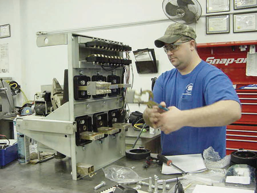
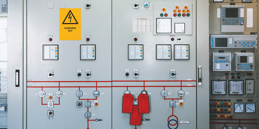
Figure 1: Low-Voltage Power Circuit Breaker or Low-Voltage Air Circuit Breaker
When I refer to LVPCBs, I actually mean what are also referred to as low-voltage air circuit breakers (Figure 1). This was the industry standard for years, but insulated-case circuit breakers have taken their place for the most part. However, hundreds of thousands of LVPCBs are probably still in operation.
NFPA 70E Requirements
The first task involved in working on a circuit breaker, for example, taking it out of service, is to tackle the necessary paperwork. Many technicians dislike paperwork, but it serves its purpose to promote safety if it’s completed properly. NFPA 70E supplies the minimum requirements — not the best practices. Article 110 includes several requirements pertaining to circuit breaker operation, although it focuses on the electrical safety program.
Everything in Article 110 is from the 2021 edition of NFPA 70E. Beginning with Section 110.5(C) Condition of Maintenance, safe work practices are presented in Section 110.5(D) Awareness and Self-Discipline, 110.5(H) Risk Assessment Procedure, 110.5(H)(2) Human Error, 110.5(H)(3) Hierarchy of Risk Control Methods, 110.5(I) Job Safety Planning and Job Briefing, 110.5(K) Electrically Safe Work Condition Policy, and 110.5(L) Lockout/Tagout Program. Sections throughout 70E explain each of these electrical safety program requirements, but that’s a different NETA World article.
Job Safety Plan
The first step in working on a circuit breaker is to complete a job safety plan where all steps are planned out and recorded. There are good reasons for this step:
- A job safety plan forces you to reason out what needs to be done: What equipment is needed, what steps will be followed as the task is performed, what PPE may be needed, what condition is the equipment in, or is that unknown?
- It allows a second qualified person to read over the job safety plan and verify that it is accurate, safely doable, and complete.
Risk Evaluation
The next step is to evaluate the risk and determine which risk control methods are needed. People tend to underplay this step, but it has tremendous importance. NFPA 70E defines risk as:
A combination of the likelihood of occurrence of injury or damage to health and the severity of injury or damage to health that results from a hazard.
We want to reduce the likelihood of an incident as much as possible. Risk of a task cannot be driven to zero unless the equipment is placed into an electrically safe work condition by de-energizing the entire bus. This may not be convenient for many reasons, but may be possible during a facility’s shutdown, after normal work hours, or during the weekend.
OSHA regulation 1910.333(a)(1) states:
Live parts which an employee may be exposed to shall be de-energized before an employee works on or near them…
To meet this requirement, the employee must be removed from the area of danger, such as by using remote operating devices or remote racking devices, wearing the proper arc-rated clothing and PPE, or other methods provided by 70E. In fact, some circuit breakers are just not safe to operate with just the use of PPE, so remote devices are needed.
Risk Factors
When working with circuit breakers, risk increases with higher voltage, higher ampacity, higher fault current, longer tripping delay (such as short time delay), and unknown operating conditions (i.e. past-due maintenance intervals, repeated mis-operations).
At some point, those factors may require the bus to be de-energized. As an example, opening and resetting a tripped 20 A molded-case circuit breaker in your house would not require any special steps unless it’s necessary to stand in water or some other unusual factor. Ramp that up to a 200 A or 300 A molded-case circuit breaker, and the risk increases substantially. PPE may be necessary due to the current rating of the circuit breaker, even though it is not specifically required in 70E. Determining the risk involved in operating that circuit breaker must be made in relation to factors the 70E Committee cannot foresee. Personally, at this current level and above, I would always wear adequate PPE. Electrical burns are very painful, and I like the idea of avoiding them.
With medium-voltage circuit breakers — or even older, drawout low-voltage power circuit breakers — the risk increases greatly because the voltage is higher (except for the LVPCB), the current handled is usually greater, there is no built-in overcurrent device, and they tend to run slower. For example, molded-case and insulated-case circuit breakers open in 1.5 to 3 cycles; in the current-limiting type, that time drops to 0.5 cycles. Medium-voltage circuit breakers open in 3 to 8 cycles, plus the operating time for protective relaying. LVPCBs open in about 4 cycles. These are their respective “instantaneous” operating times.
If an incident energy analysis has been performed, higher incident energy indicates greater risk. This is due not only to the incident energy, but also to the increased risk of arc blast at higher incident energies. This is why the 70E Committee deleted the informational note that indicated 40 cal/cm2 was a maximum exposure level. That is not what it stated, but that is the way it was being interpreted by users of 70E. If the overcurrent device, such as the circuit breaker, was not maintained properly and its lubricants began to dry out, its operating time would increase. How much? There’s no way to tell. In an arc flash, time is critical, as incident energy is proportional to opening time. Double the opening time, and the incident energy is doubled.
Another risk factor is human error. It may be someone else’s human error, not yours. It’s necessary to list all things human error could cause and what the result of each error would be. Unfortunately, people have a tendency to make errors. It’s not that they want to, but distractions, sleepiness, multi-tasking (people have a tendency to think they excel at this, which may not be true), performing the task incorrectly (what doesn’t injure or kill us becomes our way to do things), or dropping a tool, just to name a few, could cause an incident. It’s like getting on a rollercoaster: Once the ride starts, there’s no getting off. Once an incident begins, there’s no stopping it until it’s over.
Reducing the Risk
Tools are available that can help reduce the risk.
Winch
Technicians often overlook using a winch to lower the circuit breaker from its cubicle. This is done on many drawout low-voltage power circuit breaker installations, and it is convenient if used properly. I found this out the hard way when a cable popped during a removal. Luckily, no damage was done when it occurred, but if I had kept going, who knows?
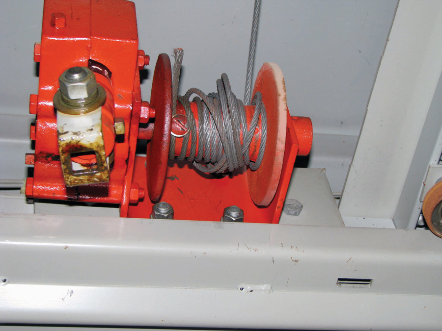
Figure 2: Typical Winch on a LVPCB Line-Up
Figure 2 shows a winch as it is typically found. Looks ready to go, doesn’t it? It is, but not the way one would think. Notice anything wrong with the cable? Each winding of the cable is overlapping the one underneath. It looks innocent, but add the weight of a circuit breaker, and it becomes hazardous. As the cable unwinds, it pops or snaps, causing the circuit breaker to bounce — often (as in my case) bounce hard. Beyond the shock that occurs, if there’s any weakness in the cable, it could snap, letting the circuit breaker fall where it may. Trying to stop an LVPCB from falling would crush Superman, and it happens fast.
A simple fix (my favorite) is to take less than five minutes to unwind the cable from the reel and wind it back while pulling on it slightly so it is straight on the reel. The cable cannot be let loose until it is connected to the circuit breaker’s lifting bars.
Lifting Bars
Figure 3a shows the lifting bars from one manufacturer, but they are all similar in the way they work. Figure 3b shows a typical LVPCB ready to be lowered properly by lifting it off its extension arms. The circuit breaker rollers must be checked before it is rolled out of its cubicle to verify they are on the extension arms and are attached properly to the circuit breaker. The cable is just out of sight in Figure 3b. It has been unwound from its reel and rewound so it is straight and any wound cable does not overlap.
Figure 3a: Circuit Breaker Ready to Lift from Its Extension Arms
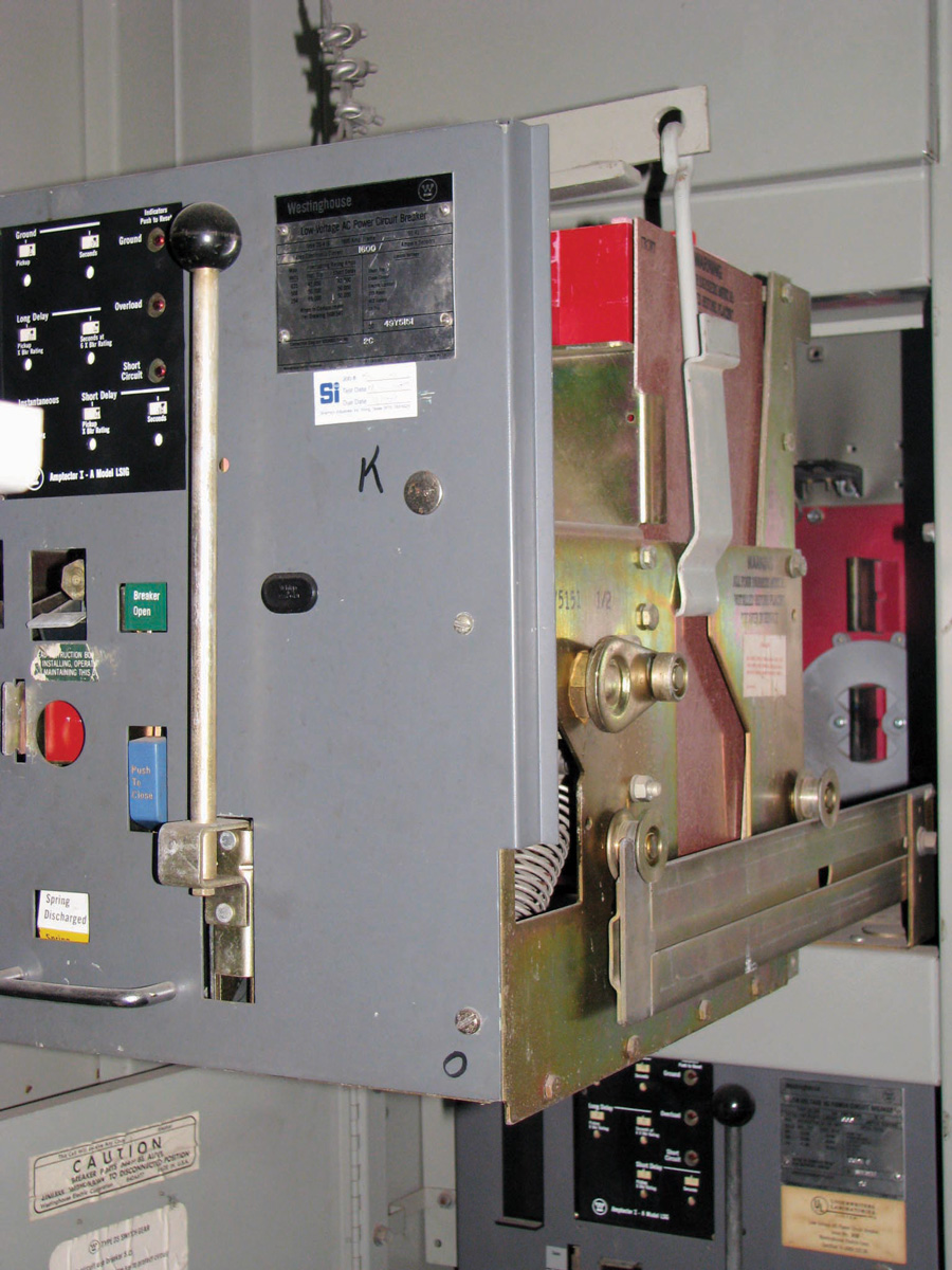
Figure 3b: Circuit Breaker Ready to Lift from Its Extension Arms
It takes two technicians to attach the lifting bars to the carriage of the circuit breaker. It’s easy to see in Figure 3a that, as one side is attached, the other side may release.
Lift
It’s no fun seeing a circuit breaker hit the floor. If no cable mechanism is available, a hydraulic lift or mechanical lift can be used. As Figure 4a and Figure 4b show, many medium-voltage manufacturers supply such a lift to install and remove their equipment. The equipment is de-energized, and the technician is wearing the correct PPE for this task.
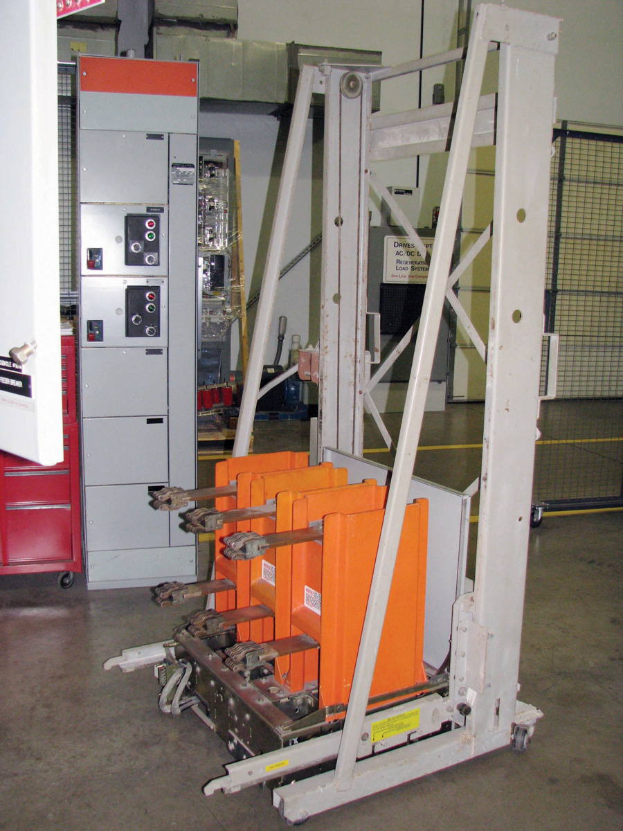
Figure 4a: Vacuum Circuit Breaker Lifting Platform
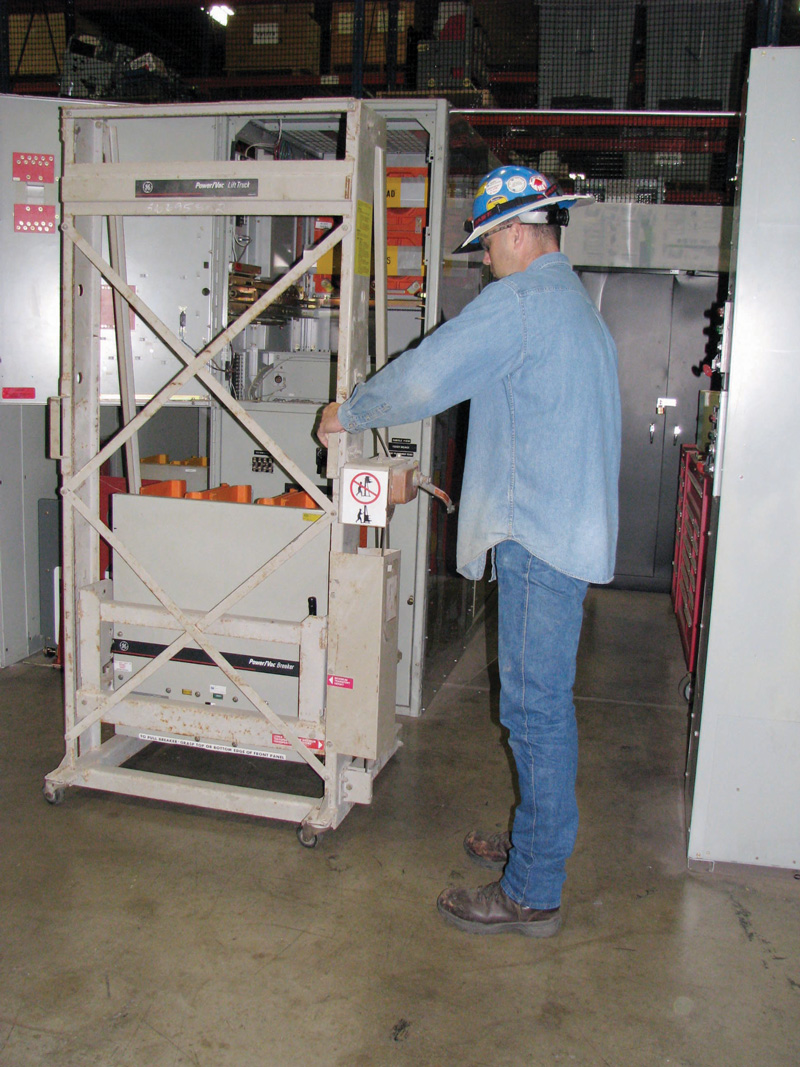
Figure 4b: Technician Installing a Drawout Vacuum Circuit Breaker
Remote Operating and Racking Devices
Figure 5a and Figure 5B illustrate why a remote operating device and a remote racking device are usually needed when operating and racking a drawout circuit breaker while it is energized. Figure 5a shows that the arms of the bus connectors are out of alignment on this medium-voltage vacuum circuit breaker.
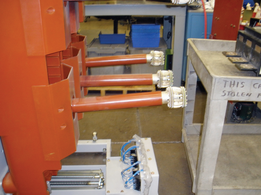
Figure 5a: Circuit Breaker with Bent Bus Connection Arms
Figure 5b (the same circuit breaker) shows the results of a vacuum bottle failure, probably due to a racking incident. Any type of drawout circuit breaker can fail when the circuit breaker bus connection makes contact with the bus. There’s no time to get out of the way. Remember the roller-coaster analogy.
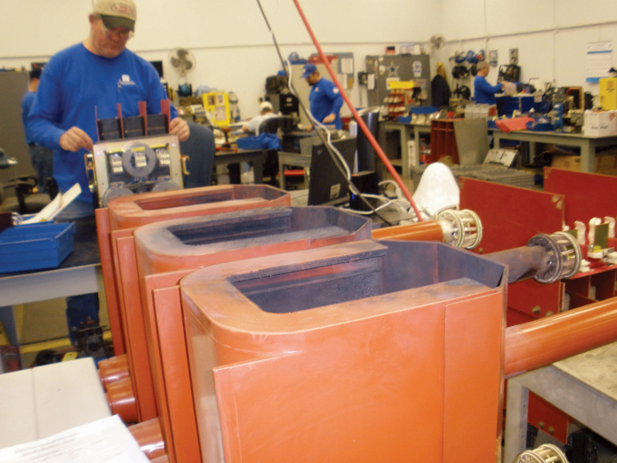
Figure 5b: Result of a Fault while Racking
Circuit breakers can also fail from being operated — opening or closing them. Figure 6a shows a bent racking gear pin from a low-voltage drawout power circuit breaker. Superman must have found his calling when he racked this circuit breaker! As a result of this abuse, if the pin had sheared off, the circuit breaker would not stop where it should have at the full connected position; it would continue to move past that position and begin to rack out again. Amazing and dangerous, as it would break contact if the technician kept racking.
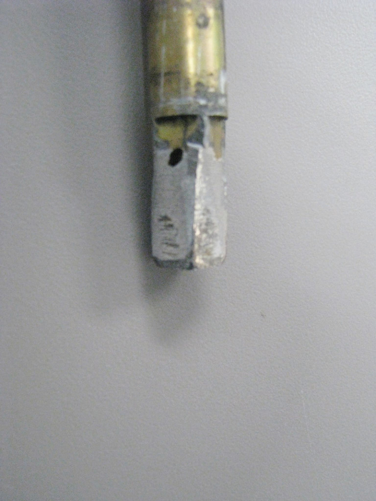
Figure 6a: Care Must Be Taken Not to Rack Too Hard
Figure 6b shows a medium-voltage air-magnetic circuit breaker. Note the light bulb on top of the contacts. This is not uncommon; I have personally seen pliers sitting on top of a 15 kV circuit breaker’s arc chutes. Note also how the contact clusters have fallen apart, causing the circuit breaker to fault. This is due to not lubricating the contact clusters, which is a good indication no maintenance had been performed.
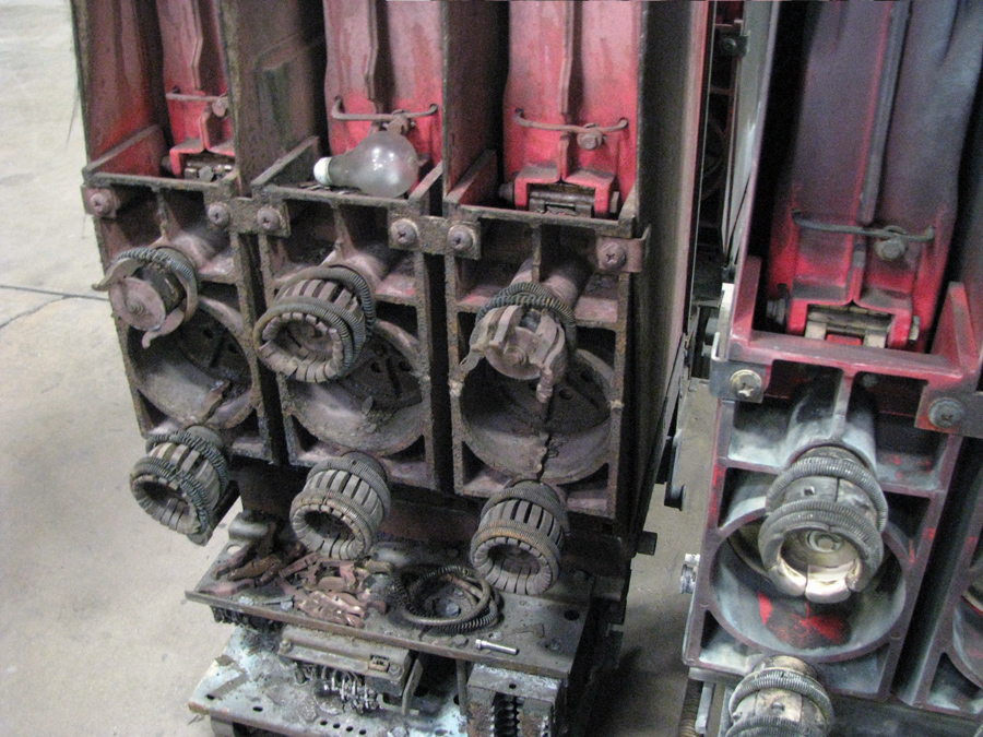
Figure 6b: Serious Neglect
Conclusion
Operating and racking circuit breakers should be done with care as well as the proper equipment and PPE. The first section in this article reviews pertinent NFPA 70E sections that apply to any task that could cause injury or even death. The second section looks at the various issues involved with operating and racking drawout circuit breakers. It’s not difficult to put the two together.
As NETA-Certified Technicians, take special care when performing tasks that could cause an incident. Remember the roller-coaster analogy: When it begins, there’s no stopping it. A special concern should be equipment that is always used and always seems to be safe. Things happen unexpectedly and, as they used to say when I was a young lad, “Surprise! You’re it!” You did not want to be it then, nor do you want to be it now.
Work safe. Don’t rush or be distracted. The task is not worth doing quickly for any reason, and you certainly don’t want a phone call or loud noise to make you lose your attention, even for a moment.
 James (Jim) R. White, Vice President of Training Services, has worked for Shermco Industries since 2001. He is a NFPA Certified Electrical Safety Compliance Professional and a NETA Level 4 Senior Technician. Jim is NETA’s principal member on NFPA Technical Committee NFPA 70E®, Electrical Safety in the Workplace; NETA’s principal representative on National Electrical Code® Code-Making Panel (CMP) 13; and represents NETA on ASTM International Technical Committee F18, Electrical Protective Equipment for Workers. Jim is Shermco Industries’ principal member on NFPA Technical Committee for NFPA 70B, Recommended Practice for Electrical Equipment Maintenance and represents AWEA on the ANSI/ISEA Standard 203, Secondary Single-Use Flame Resistant Protective Clothing for Use Over Primary Flame Resistant Protective Clothing. An IEEE Senior Member, Jim was Chairman of the IEEE Electrical Safety Workshop in 2008 and is currently Vice Chair for the IEEE IAS/PCIC Safety Subcommittee.