
The 2018 edition of NFPA 70E is still active, even though many people are looking forward to a new edition in 2021. The 2021 edition will be released to the public in late September or early October, first in pdf form, then as a printed document. Until that release, the current edition must be referenced.
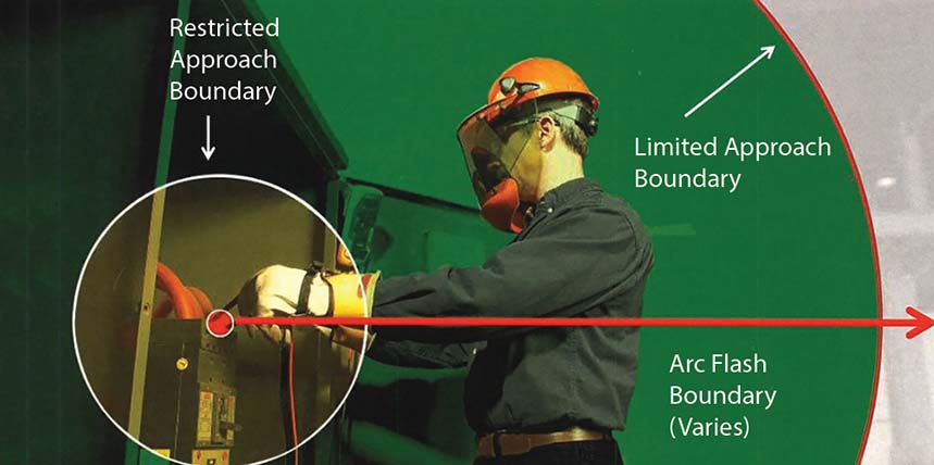
Shock Boundaries
Shock remains the number-one cause of electrical fatalities and has been for several years. Arc flash gets the most attention because of the serious injuries caused by an arc flash, not to mention the visual and audible results, which tend to be more impressive than a shock. After all, what electrician or technician hasn’t been shocked at one time or another and just received a slight jolt, maybe a sting — and you look around to make certain no one was watching? We tend to think of low-voltage shocks as more of a nuisance then a real threat, but that is wrong-headed thinking.
Somewhere in the 1999–2002 range, an IEEE Electrical Safety Workshop presentation by Lanny Floyd and Danny Liggett of E.I. DuPont included Figure 1, which was the result of a study done at their facilities. Since these were industrial sites and not utilities, it’s not surprising to see that the over-600 V range is only 11% of the fatalities. It is also not surprising that 250–600 V (mostly 480 V) is the largest percentage of fatalities at 45%. What is very surprising to most people is that 100–250 V is right next to it at 39%. Now, this was an old paper, but the percentages even now tell a real story about the risk involved in dealing with lower voltages.
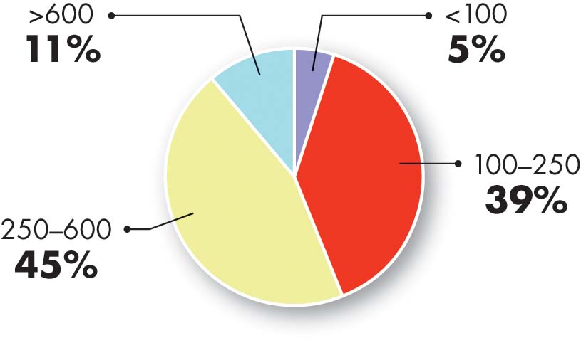
Figure 1: Lethal Voltages at an Industrial Facility
In NFPA 70E-2018, Article 130 Section 130.4 outlines the shock protection boundaries. But before the tables, Section 130.4 Shock Risk Assessment states:
(A) General. A shock risk assessment shall be performed:
(1) To identify shock hazards
(2) To estimate the likelihood of occurrence of injury or damage to health and the potential severity of injury or damage to health
(3) To determine if additional protective measures are required, including the use of PPE
N (B) Additional Protective Measures. If additional protective measures are required, they shall be selected and implemented according to the hierarchy of risk control identified in 110.1(H). When the additional protective measures include the use of PPE, the following shall be determined:
(1) The voltage to which personnel will be exposed
(2) The boundary requirements
(3) The personal and other protective equipment required by this standard to protect against the shock hazard
“N” indicates that a new section was added. 130.4(A) states the purposes of performing a shock risk assessment, while 130.4(B) provides the needed information concerning “additional protective measures” as provided in Section 110.1(H)(3). A quick look at that section shows use of PPE as the lowest priority, while placing the equipment in an electrically safe work condition (elimination) is highest. Due to issues that arose using standards from American National Standards Institute (ANSI) and American Industrial Hygiene Association (AIHA) in this particular application, it won’t be carried over into the 2021 edition, although its intent will be. Elimination is always the first choice; PPE is the last, although using appropriate PPE is often unavoidable.
The other risk control methods listed in 110.1(H)(3) should be incorporated to the degree possible. It would be unsafe (and not too smart) to troubleshoot energized electrical conductors and circuit parts without using PPE. Troubleshooting increases the shock risk because if the equipment was in normal operating condition, per Section 110.2(A)(4), troubleshooting would not be necessary; the risk of arc flash also increases. The fact that equipment requires troubleshooting indicates it’s at risk of failure. Not everyone catches that; it’s just a normal day on the job — but it is not normal. More detailed information on the hierarchy of risk control methods is found in Informative Annex F.
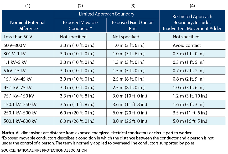
The shock approach boundaries are easy enough to interpret from Table 130.4(D)(a) for AC voltages and 130.4(D)(b) for DC voltages. One key point to remember is that this table has two columns for the limited approach boundary. Column 2 is for exposed movable conductors, such as overhead power lines. It is also for when mechanical equipment is approaching an exposed conductor, movable or otherwise. Equipment tends to bob and sway, especially if the wind is blowing or the lift is extended. Another point to remember is that only qualified persons should approach overhead conductors unless they have been locked out/tagged and grounded. In industrial facilities, this often must be done by the local utility. Table 1 illustrates Table 130.4(D)(a); Table 2 illustrates 130.4(D)(b).
Table 1: NFPA 70E Table 130.4(D)(a)
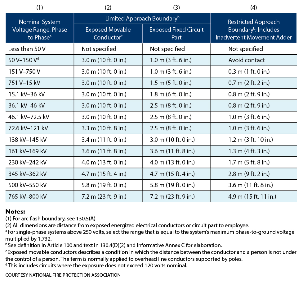
Table 2: NFPA 70E Table 130.4(D)(b)
Bear in mind that these distances are approximated in the field. No one is going to take out their metal tape measure and try to be as accurate as possible. That was never the intent. If you’re farther than the indicated distance, you’re fine. Always try to leave a little extra.
Column 3 is for exposed fixed parts, such as installed equipment, which is what most of us work on. While column (2) and column (3) are the closest an unescorted, unqualified person can approach energized parts or conductors, column (4) is the restricted approach boundary, and only qualified persons can cross it. If you’re not qualified, never cross the restricted approach boundary, and only cross the limited approach boundary if you are continuously escorted by a qualified person. The fact that a person is unqualified means they cannot determine energized parts from de-energized parts and/or cannot choose appropriate PPE. They are putting themselves and others at risk if they do.
Additional Protective Measures
Many people interpret the phrase “additional protective measures” as saying “use PPE.” Section 130.4 refers the user to 110.1(H)(3), and that section refers the user to Informative Annex F Risk Assessment and Risk Control. A quick look at Informative Annex F shows Table F.3 The Hierarchy of Risk Control Methods. Unlike the main text in Section 110.1(H)(3), Table 3 provides some examples of each risk control method. More people should read through the Informative Annexes. They may be optional, but they often contain valuable information that gives more complete information than can fit into the main text.
Table 3: NFPA 70E Table F.3
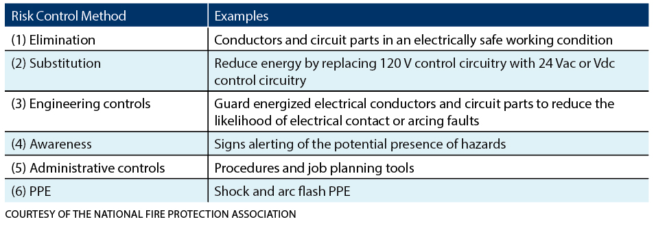
Table F.3 provides good guidelines for implementing each of the hierarchy of risk control methods. It is very likely that more than one risk control method will be used for a given task.
- Elimination is the first priority (as it should always be), such as placing equipment into an electrically safe work condition.
- Substitution is often difficult to achieve unless it is a design element.
- Engineering Controls such as guarding are often used in conjunction with other methods. You can find more on guarding in the 70E & NETA column in the 2016 Summer issue of NETA World Journal.
- Awareness, such as using signs, barrier tape, and attendants, is also often used with others.
- Hopefully, Administrative Controls would always be used to plan the task and guide technicians through it.
- Last is PPE, that is, appropriate PPE for the task and the hazard.
Used together, these risk control methods will greatly reduce the risk in performing electrical tasks, although even when using these methods, there will always be some residual risk or leftover risk that was not resolved. This residual risk must be evaluated to determine if it is still safe to perform the task.
Choosing rubber-insulated gloves and leather protector gloves is relatively simple. Figure 2 is an example of an ASTM glove chart reflecting Table 1 in ASTM F496, Standard Specification for In-Service Care of Insulating Gloves and Sleeves. The glove chart also shows the maximum-use voltage for each glove class, the label color it should have for that class, and the test voltages — both AC and DC. This example is from W.H. Salisbury, but many variations are available on the internet.
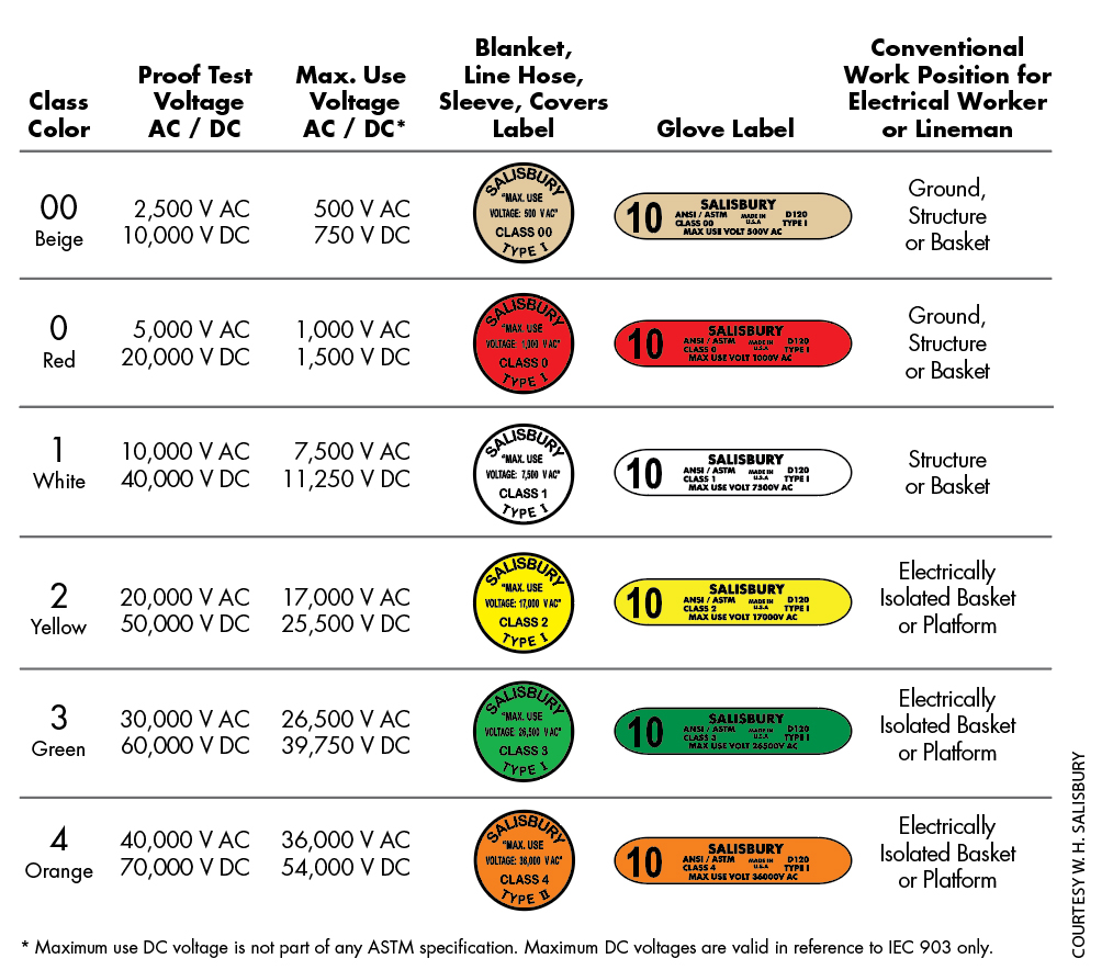
Figure 2: ASTM Glove Labeling Chart
Arc Flash Boundary
Shock boundaries are fairly straightforward. The arc flash boundary is more difficult. IEEE Std. 1584, IEEE Guide for Performing Arc-Flash Hazard Calculations was updated in 2018 with new calculations and parameters. The prior exception for systems less than 240 V/125 kVA has been eliminated, as recent testing has shown that sustainable arcs are possible, but less likely. Read that as “it could happen” and no one would like the results.
Arc flash kills three or four people a year. That may sound like a very small number (except to those who are killed), but the injuries from arc flash events are the cause of greatest concern. There are many injuries from arc flashes, and they carry life-changing consequences for those involved. As an expert consultant and expert witness, I have seen the damage these incidents can do. Regardless of who is at fault, the person who has been seriously injured by an arc flash will never be the same. Understanding how to determine the risk involved in a task, how to choose the appropriate PPE, and how to perform the task safely is paramount for technicians and is required to be considered a qualified person.
NFPA 70E statements about the arc flash risk assessment are almost verbatim from the shock risk assessment. Section130.5 states:
N (A) General. An arc flash risk assessment shall be performed:
(1) To identify arc flash hazards
(2) To estimate the likelihood of occurrence of injury or damage to health and the potential severity of injury or damage to health
(3) To determine if additional protective measures are required, including the use of PPE
N (B) Estimate of Likelihood and Severity. The estimate of the likelihood of occurrence of injury or damage to health and the potential severity of injury or damage to health shall take into consideration the following:
(1) The design of the electrical equipment, including its overcurrent protective device and its operating time
(2) The electrical equipment operating condition and condition of maintenance
N (C) Additional Protective Measures. If additional protective measures are required they shall be selected and implemented according to the hierarchy of risk control identified in 110.1(H). When the additional protective measures include the use of PPE, the following shall be determined:
(1) Appropriate safety-related work practices
(2) The arc flash boundary
(3) The PPE to be used within the arc flash boundary
Table 130.5(C) shall be permitted to be used to estimate the likelihood of occurrence of an arc flash event to determine if additional protective measures are required.
Almost verbatim, Section 130.5(B), which contains some very important information, was added in addition to 130.5(A) and 130.5(C). The 70E user is to estimate the likelihood of occurrence and the severity of injury if an arc flash were to occur. Two items are listed to assist in determining the likelihood of occurrence:
- The design of the equipment, the overcurrent protection, and the time of its operation
- The operating condition of the equipment, including its condition of maintenance
Remember, if troubleshooting is being performed, the equipment is in distress. It is not in normal operating condition. Unmaintained electrical equipment is also hazardous, like a ticking time bomb that could go off at any minute. If any of these conditions indicate an issue, de-energize and isolate the equipment before continuing. No one has ever been promoted for injuring themselves or others or by damaging expensive equipment. Well, I do know one, but that was in the bad old days, and the facility manager thought the perpetrator was “a company man.” Don’t count on that today. Unsafe conduct is the quickest way out the door (or fence).
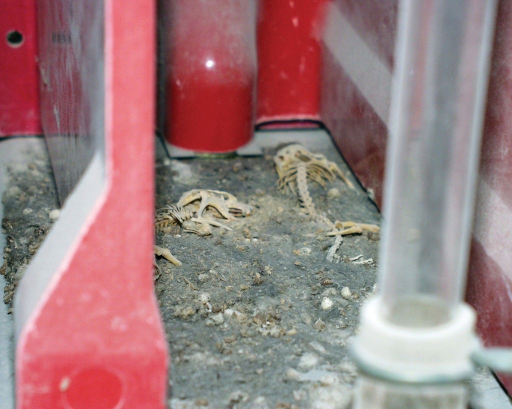
Section 130.5 states that Table 130.5(C) is permitted to be used to determine the likelihood of occurrence. “Permitted to be used” should read “use at your own risk.” Careful evaluation is required to determine if Table 130.5(C) has any relevance at all. Table 4 shows a partial Table 130.5(C). For the most part, it does well on normally operating equipment. But what if there’s a rat (or rats) in the circuit breaker? You would never see it coming. Of course, neither did the rats in this photo. No arc flash was initiated, but it was pretty close.
Once the likelihood of occurrence is determined, the potential severity of injury or damage to health must be appraised. This is where 130.5(B) comes into play. If an arc flash were to occur, what would be the impact on the person performing the work, others nearby, or the equipment? It could range from an “oops” to a disaster. Just as in the shock risk assessment, the arc flash risk assessment calls for additional protective measures, and once again, PPE is at the bottom of the options. I prefer to view IEEE 1584 calculations as educated estimates since everything has to work well for them to even be close. That is where normal operating condition and maintenance condition can make a huge difference. If the protective device does not operate within the manufacturer’s specifications, there is no method to determine the resulting arc energy.
Calculations performed to the new edition of IEEE 1584 are best, but not always done. Table 130.7(C)(15) and Table 130.7(C)(16) are the backup plan. They are certainly not perfect, but as long as their limits are observed, they tend to be conservative. They are conservative because everything is “guesstimated.” Better to be a bit over-protected than under-protected. If calculations have been made and arc flash warning labels are installed (and legible), Table 130.5(G) “is permitted” to be used to select PPE. For the sake of brevity, I’ll skip using partials of those tables as figures.
Conclusion
The best plan is to avoid the hazard, reduce the risk, and wear PPE where appropriate. Back when the 70E first introduced the arc flash clothing selection tables (in the 2000 edition), Committee Chair Ray Jones said, “What people wear is not as important as that they wear something.” This may sound all backwards today, but his point was that most technicians of the day weren’t wearing any PPE for arc flash, so something was better than nothing. This was all pre-IEEE 1584, and there simply was no other guidance until Paul Hamer, then with Chevron, introduced the tables they used at their sites.
Electrical safety is an on-going project. Much like the National Electrical Code, it may never be finished, as much is learned every year. The 70E Committee members are unified in their goal to make the workplace safer. We don’t always agree on how to meet that goal but, in the end, we come to a consensus we are satisfied meets the purpose. I once presented a paper, and a participant asked, “How can we trust the 70E if everyone doesn’t agree?” My response: “Why wouldn’t you want us to debate, arm wrestle, or whatever to provide the best safety standard possible?”
NFPA 70E is close to being in a maintenance phase where large revisions aren’t necessary. The committee’s focus has been to make 70E easier for the average technician to use and apply without having to ask for interpretations. It’s there; it’s clear and understandable. If you have any suggestions for the committee, a visit to the NFPA website (nfpa.org/70e) allows suggestions, comments, and public Inputs.
 James (Jim) R. White, Vice President of Training Services, has worked for Shermco Industries since 2001. He is a NFPA Certified Electrical Safety Compliance Professional and a NETA Level 4 Senior Technician. Jim is NETA’s principal member on NFPA Technical Committee NFPA 70E®, Electrical Safety in the Workplace; NETA’s principal representative on National Electrical Code® Code-Making Panel (CMP) 13; and represents NETA on ASTM International Technical Committee F18, Electrical Protective Equipment for Workers. Jim is Shermco Industries’ principal member on NFPA Technical Committee for NFPA 70B, Recommended Practice for Electrical Equipment Maintenance and represents AWEA on the ANSI/ISEA Standard 203, Secondary Single-Use Flame Resistant Protective Clothing for Use Over Primary Flame Resistant Protective Clothing. An IEEE Senior Member, Jim was Chairman of the IEEE Electrical Safety Workshop in 2008 and is currently Vice Chair for the IEEE IAS/PCIC Safety Subcommittee.