
Diagnosing the condition of complex systems such as high-voltage rotating machines has never been a simple task. Design requirements, the use of different materials, and demanding operating conditions require multiple off-line tests and on-line monitors to provide information on the machine’s condition. Some tests only yield simple measurement results without high diagnostic value. This article describes the application of various off-line test techniques to assess stator and rotor insulation and stator core.
Testing Rotating Machines
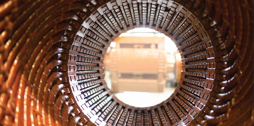
Although electrical rotating machines can be divided into two very broad groups — motors and generators — and can be of different designs, they all have a rotor and a stator. The two main parts of a stator are the stator core and the stator winding, which consists of a conductor and insulation (Figure 1). The stator core of a typical large rotating machine can weigh 220 tons; it can be 15–25 ft long, with an internal diameter of 5 ft. It is built from a stack of insulated steel sheets or laminations, each 14–19 mils thick, coated on each side with a layer of electrical insulation to prevent current flow between them.
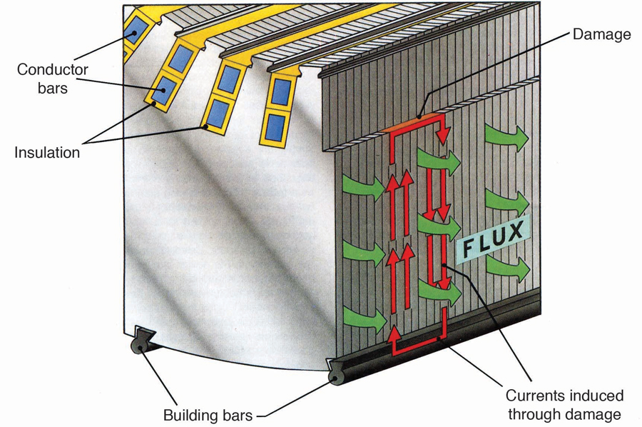
Figure 1: Stator Core Cross-Section
Core failure commonly occurs when the insulation on a group of laminations is damaged and an electric circuit is created. The machine’s rotating magnetic field induces a current along the circuit, which in turn creates a hot spot within the stator core. The stator winding of a high-voltage rotating machine is usually made of form-wound bars or multi-turn coils installed in stator core slots. The conductors are commonly made of copper; various types of insulation have been used over the last 100 years, most based on the application of mica materials in various forms. Two distinctive parts of the stator winding are the slot and the endwinding.
The failure mechanisms that affect the condition of stator winding insulation can broadly be grouped under thermal, electrical, ambient, and mechanical causes. The coils and bars are exposed to large mechanical forces at twice the ac operating frequency as well as much larger forces in the case of machine faults or system disturbances. Several means of mechanical support are used to prevent winding movement, both within slots and in the endwinding area. Within slots, the wedging system, which consists of a top wedge and sometimes side wedging, is usually sufficient to prevent movement of the stator winding. However, at the endwinding areas on both sides of the core, this task is more complex, since axial movement of the winding due to thermal dilatation must be allowed. Radial and tangential movement of the endwinding in normal operation and during faults should be limited. The preferred method is to use non-magnetic and usually non-metallic brackets, braces, support rings, and spacer blocks.
As a result of such a complex design, many off-line and on-line tests have been developed to help assess the condition of rotating machines.
HV Machines Off-line Testing
Typical tests can be divided into off-line and on-line, each having advantages and disadvantages. Off-line testing requires machine shut-down and an external source of energy, while on-line tests generally require installation of a sensor during shut-down; the sensor will be used once the machine is back in operation. Off-line electrical stator winding tests can be divided into ac and dc tests.
High Potential Testing
A high potential (HIPOT) or dielectric withstand test (Figure 2a) can be performed using an ac or dc power supply. The purpose of the test is to detect major problems in the insulation. The expectation is that high voltage applied to the stator winding will result in insulation breakdown at the location of a problem. Although insulation in good condition can survive voltage levels much higher than those recommended for ac or dc HIPOT, this test is destructive in its nature and is of limited diagnostic value. The test can be performed in various ways, as described in IEEE 95 and IEC 60034 for dc power, IEEE C50.10 and IEEE 43 for ac power frequency, and IEEE 433 for 0.1 Hz HIPOT testing. AC and dc HIPOT tests are not diagnostic tests, since the winding either passes or fails. Insulation condition is not indicated except a pass or fail criterion. HIPOT testing of the stator and rotor windings has similar diagnostic value, but it should be noted that rotor HIPOT level could be 5 times higher than its rated dc voltage, which is not the case for stator HIPOT level.
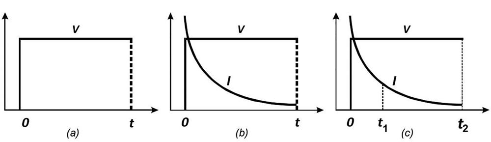
Figure 2: High Potential (HIPOT), Insulation Resistance (IR), and Polarization Index (PI) Tests
Insulation Resistance Testing
The insulation resistance (IR) test (Figure 2b) can be applied to stator and rotor windings and has been used since the introduction of electrical rotating machines. The purpose of the test is to measure the resistance between the conductor of the rotor or stator winding and the rotor or stator core. Since stator or rotor winding insulation is not perfect, the measured resistance is not going to be infinite, and with a lower measured value, it is more likely that a problem is present. IR testing is usually done by applying dc voltage between 500 V and 10,000 V. Acceptance guidelines provided in IEEE 43 make this test a useful tool to detect contaminated or wet windings. One major problem with IR testing is that the measurement results are strongly dependent on temperature (ambient and winding) and therefore cannot be easily compared. Some experiments have indicated that a temperature change of 5–20 degrees C can result in a 50 percent reduction in the resistance of modern polyester and epoxy insulations. Given that attempts to correct measurement results at different temperatures to a standard temperature (40 degrees C) are not very reliable, the diagnostic value of this test is also not very high.
Polarization Index Testing
The polarization index (PI) test is an improvement over the IR test because it is relatively insensitive to the effects of temperature change. PI is the ratio of the measured insulation resistance after applying dc test voltage for ten (t₂) minutes and at one minute (t₁) (Figure 2 (c). In some cases, IR values are measured after 60 seconds and 15 or 10 seconds, or after 5 minutes and 30 seconds. PI test results are highly dependent on ambient humidity and cannot be corrected; comparing results is therefore impossible. Although the results of IR and PI tests are numerical values and can be seen as an improvement over HIPOT testing, the diagnostic value of these tests is still limited by ambient condition changes and a lack of agreement on an acceptable time ratio for the PI test.
Time Stepped Voltage Testing
The timed stepped voltage test is an improvement over the previously described direct voltage tests. For this test, direct high potential is applied in a series of several voltage steps at regular time intervals as shown in Figure 3(a). Current readings are taken at the end of each interval, and the I-V (current versus voltage) readings are hand-plotted on graph paper. During and after testing, the data is examined for increases in conduction current or other variations versus applied potential, which are possible indications of stator insulation weakness. Since the maximum test voltage is above the normal operating stress, the test can also serve as a proof test. To minimize the effects of dielectric polarization, the test voltage may be held at each level long enough to allow the polarization current to decay to a negligible value. Since it is usually not practical to hold the test voltage at each level long enough to make the polarization current negligible and to shorten the time required to obtain the I-V curves of stator insulation, complex voltage-to-time schedules were developed (see F.R. Schleif).
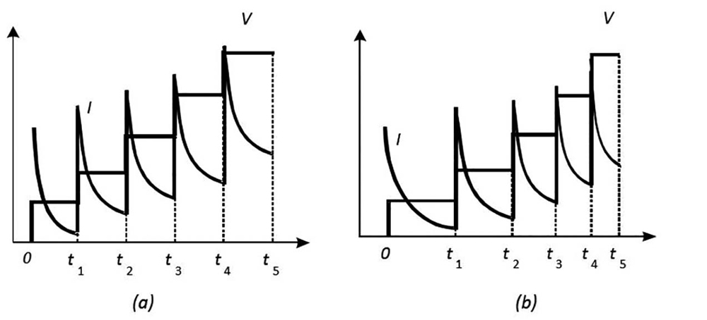
Figure 3: Time Stepped Voltage Testing
The basic idea of these test schedules is to adjust the voltage in steps according to a predetermined, diminishing time schedule so that the polarization component of the measured current is proportional to the applied voltage (Figure 3b). In effect, the voltage-time schedules attempt to linearize the polarization current so that relative changes in the conduction current become more readily discernible. Nevertheless, even with the use of graded time intervals, it may be difficult to detect subtle changes in conduction or ionization. A time stepped voltage test generally requires two people: one to monitor the time intervals and record the measured data, the other to apply the voltage steps and read the current meter. Tests performed in this manner rely on individual judgment and actions to control the test time intervals, apply uniform voltage increments, and accurately read and average a fluctuating current meter. This human factor can result in poor data quality and impact repeatability of the measurements. Such uncertainty decreases confidence in the data and may even lead to misdiagnosing insulation condition, therefore minimizing the diagnostic value of this test.
DC Ramp Voltage Testing
A third variation and further improvement over other direct voltage tests is the dc ramp voltage test where dc voltage is linearly increased at a constant rate from zero to the maximum test voltage. This method represents a major advantage. As a result of the steady increase in voltage (dV/dt = C, usually 1 or 2 kV per minute), the capacitive charging current is constant; the test result is shown graphically, so this can be ignored, unlike in any other dc test. The total current (sum of capacitive, polarization, and leakage currents) is plotted versus the applied voltage. The graphical presentation of the test result is a more helpful diagnostic tool. In the case of defect-free insulation, the measured current increases linearly with applied voltage, and any deviation from the expected linear response can be easily observed. Figure 4 shows a typical result from a new epoxy-mica insulation system. IEEE 95 provides general guidelines and some typical dc ramp test results. Since this test method is the most sensitive way to detect leakage current instability, it is superior in detecting problems that cannot be identified by other tests, such as incompletely cured epoxy insulation or moisture within insulation.
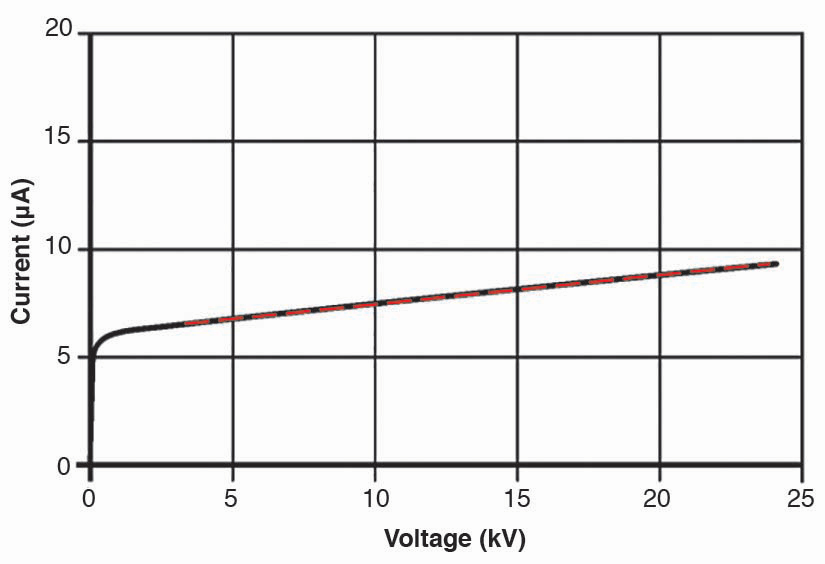
Figure 4: Typical DC Ramp Voltage Test from New Epoxy Mica Insulation
Figure 5 indicates the dc ramp test results for all three phases of a 30 MVA, 6.9 kV generator after installing a new winding. Only phase B results were acceptable, while a major deviation from the expected linear response is easily visible in phase A and phase C results. AC and dc HIPOT tests and the PI test did not indicate the presence of problems on phases A and C. After detection by the dc ramp test, many other tests failed to identify the location of the insulation problem. The winding was sectioned first into parallel sections and then into coils, and the dc leakage current was measured to locate two faulty coils on phases A and C.
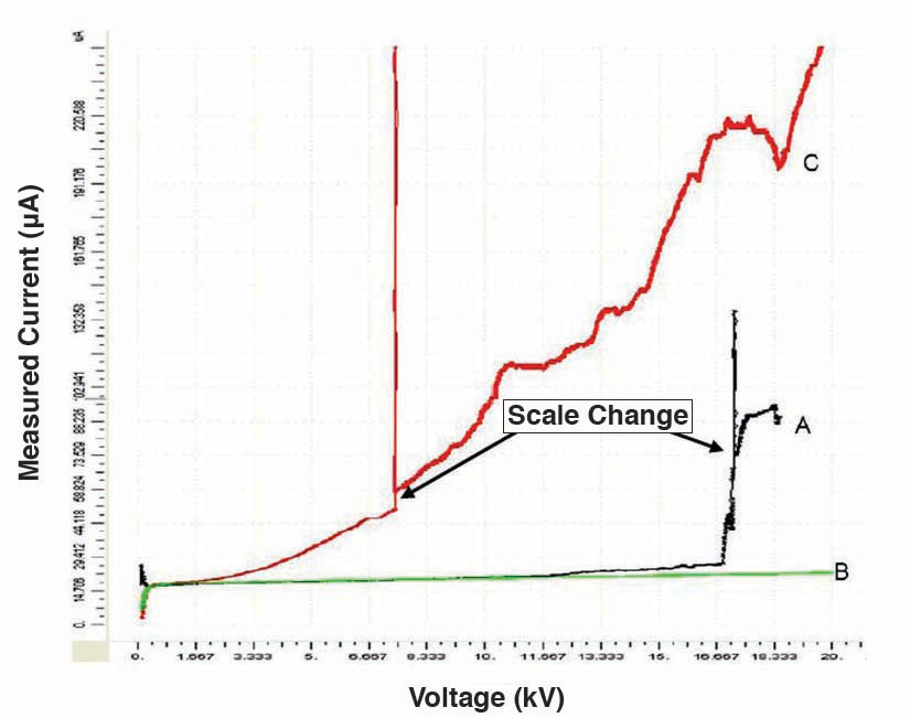
Figure 5: Unacceptable DC Ramp Test Result on Phases A and C
Although as potentially destructive as any other HIPOT test, the dc ramp test is most likely to help a user avoid failure during the test. Based on the experience of the United States Bureau of Reclamation, the failure rate after 5,400 tests was lower than 0.01 percent or just four sudden failures without precursor to a failure. The diagnostic value of this test compared to other dc and ac HIPOT tests is significant. The comparison of dc ramp results from the same or different machines is a useful tool for detecting stator winding insulation problems.
Stator Core Testing
Traditionally, the only method of testing inter-laminar insulation in stator cores was the high flux ring test (or loop test). This requires the rotor to be removed and a massive excitation winding to be installed through the core to generate a circumferential (ring) magnetic flux around the core. To provide the required level of flux (typically 80–100 percent of rated flux), several loops of high-voltage, high-current-carrying capacity cable must be connected to a large power source (3-4 MVA for a 500 MW generator). Ideally, the core is energized for a few hours to produce measurable tooth-tip temperature rises for deep-seated faults located near slot bases. Hot spots are then detected using thermal sensing equipment. The principal disadvantages of the loop test are the installation of the winding, the high power requirement, high-voltage safety concerns, the difficulty of detecting deep-seated faults, and the risk of further core damage due to the absence of normal cooling systems.
Electromagnetic Core Imperfection Detector
Although the diagnostic value of the high flux ring test is not low, the difficulties related to excitation requirements led to development of a low-power core test known as the electromagnetic core imperfection detector (EL CID). EL CID also uses a temporary ring flux winding, but it is much lighter and requires only a 3 kVA supply for a typical 500 MW turbine generator or less than 5 kVA for a large hydro generator. The flux level required is only 4 percent of the rated value, so only small currents flow through any damaged area (typically between the fault and rear building key bars as shown in Figure 5). Core heating from such currents is insignificant, but EL CID detects the actual currents using a very sensitive electromagnetic technique; faults are readily detected even if they are located deep down in the slots between the teeth.
Chattock Potentiometer
A special pickup coil known as a Chattock potentiometer is used to measure the magnetic fields produced in the air by current flowing along the core surface. The voltage induced in the coil is proportional to the line integral of the magnetic field along its length, i.e., to the magnetic potential difference between its ends. Since the core fault current circuit has significant resistance, the fault current is substantially in phase with the fault voltage and in-phase quadrature (shifted by ninety degrees) from the excitation flux. EL CID exploits this phase relationship and virtually eliminates the signal from the excitation current by using a phase-sensitive detector to measure this quadrature component of the fault current (the core fault heat producing component). The component in phase with the excitation current is called the PHASE (or P) and the component indicating the core imperfections is referred to as the QUAD (or Q) component.
To carry out the EL CID test, the Chattock is adjusted to the slot/tooth width and scanned along each and every tooth pair. The current responses (Y-axis) and the distance from the core end (X-axis) are recorded. These traces are examined, and faults are apparent when the quadrature component exceeds a certain threshold. In a perfect, fault-free, uniformly constructed generator, a slot QUAD trace would be a straight line along the zero axis and the PHASE trace would be another straight line with an offset depending on the excitation current. In practice, however, a number of effects can cause QUAD trace deviation from zero level (e.g., stator winding currents, varying core loss).
Analyzing QUAD Traces
At the standard excitation level of 4 percent of rated flux, a QUAD current level of 100 mA was established in the early days of the technology as a threshold above which more detailed examination is required. Although correlation with thermal tests depends on a number of factors, the 100 mA QUAD threshold corresponds approximately to a rise of 5–10 degrees C in the core temperature. Faults are identified and located by examining the traces measured along and around the core, correlating features on adjacent slots. Figure 6 shows laboratory measurements on a section of core with three artificial faults, each of equal severity and each 0.4 in long, applied at various positions on a tooth. The shape and polarity of recorded adjacent slot QUAD traces is used to identify the location of the fault. The amplitudes of the measured currents were fairly constant (Y-axis) even for fault C near the bottom of a slot.
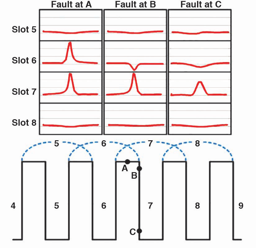
Figure 6: EL CID Quad Traces Fault Location Analysis
EL CID Advantages
This higher sensitivity to deep-seated faults is one of the important advantages of EL CID over the high flux ring test. Many field test comparisons verified the sensitivity of EL CID in comparison to the high flux ring test; all confirmed that for every hundred mA of QUAD current, the temperature increase at the fault was in the range of 5–10 degrees C for all three types of high-voltage rotating machines (hydro and turbine generators and motors).
The correct interpretation of the EL CID test result depends on the polarity of the measured QUAD response in relation to the polarity of the measured PHASE signal, both recorded by the instrument. If the QUAD signal has the opposite polarity to the PHASE signal at the same distance, then a core fault lies within the span of the Chattock. This criterion is also important to properly recognize heat-generating faults from various core imperfections that would not cause hot spots and therefore would not be detected by the high flux ring test. As a result, interpretation of EL CID results is relatively simple, thus increasing the test’s diagnostic value.
Conclusion
Condition diagnostic analysis of rotating machines has evolved from off-line testing to a combination of off-line tests and on-line monitoring. No single test is perfect or sufficient to completely diagnose the condition of a rotary machine, and presenting multiple measurement results graphically is frequently more valuable than a simple numerical reading. Further improvement can be gained by combining visual inspection with information from on-line monitors that use multiple technologies, including partial discharge, rotor flux, shaft voltage and current monitoring, and endwinding vibration monitoring. Watch for more information on these technologies in Part 2 of this article.
References
Greg C. Stone, Ian Culbert, Edward A. Boulter, Hussein Dhirani. Electrical Insulation for Rotating Machines: Design, Evaluation, Aging, Testing, and Repair, 2nd Edition, July 2014, Wiley-IEEE Press.
B.K. Gupta, G.C. Stone, J. Stein. “Stator Winding Hipot (High Potential) Testing,” IEEE Electrical Insulation Conference, Montreal, QC, Canada, 31 May – 3 June 2009.
Relu Ilie, Greg Stone. “Turbine Generator Rotor and Stator Winding Hipot Testing,” IEEE Electrical Insulation Magazine, March 2012.
Lory Rux, Mladen Sasic. “Advantages of the Ramped Direct High-Voltage Method of Assessing Stator Winding Insulation Condition,” HydroVision Conference, August 16-20, 2004, Montreal, Canada.
F.R. Schleif. “Corrections for Dielectric Absorption in High Voltage D-C Insulation Tests,” AIEE Transactions (Power Apparatus and Systems), Vol. 75, Part III, pp.513-517, 1956.
Bert Milano. “Acceptance Testing Stator Windings Using Ramped High-Voltage DC Testing,” Doble Conference, 2006.
John Sutton, Mladen Sasic, David Bertenshaw. “30 Years’ Experience with EL CID Stator Core Testing,” Iris Rotating Machine Conference Long Beach, CA, 2008.
D. R Bertenshaw, A. C. Smith. “Field Correlation between Electromagnetic and High Flux Stator Core Tests,” 6th IET International Conference on Power Electronics, Machines and Drives (PEMD), Bristol, March 27-29, 2012.
D. B. Paley, et al. “Verification of the Effectiveness of EL CID on a Hydrogenerator Stator Core,” Hydrovision Conference, 1998 pp. 1-14.
K. Ridley. “Hydrogenerator EL CID results referred to High Flux Ring Test results,” CIGRE Session 2002, pp. 1-9.
 Mladen Šašić, PE, IEEE Senior Member, is the manager of Rotating Machines Technical Services with IRIS Power, Canada. He has more than 30 years’ experience in the design and testing of high-voltage electrical power equipment. He is a registered Professional Engineer in Ontario, Canada. Mladen received a BS in electrical engineering from Sarajevo University, Yugoslavia, in 1987. He coauthored the Handbook of Electrical Motors, which published in 2004, and has written more than 100 technical papers.
 Connor Chan has been a Rotating Machines Engineer at IRIS Power since 2001. He previously was Field Service Manager. Connor received his BS in electrical engineering from the University of Hong Kong. He is a member of IEEE, the Institution of Engineering & Technology (formerly IEE, UK), and the Institution of Engineers Australia, and is a Chartered Engineer.