
Diagnosing the condition of complex systems such as high-voltage rotating machines has never been a simple task. Design requirements, the use of different materials, and demanding operating conditions require multiple off-line tests and on-line monitors to provide information on the machine’s condition. Part 1 of this article described the application of various off-line test techniques to assess stator and rotor insulation and stator core. Part 2 addresses the additional improvements that can be gained by combining visual inspection with information from on-line monitors that use multiple technologies.
On-line testing has many advantages, including two that are the most important: The machine does not have to be stopped for the test, and normal operating conditions (temperature, current, etc.) are present. However, on-line testing requires permanent or temporary sensors to be installed. The two tests performed most frequently with the machine in operation are the partial discharge test of stator winding and the detection of shorted turns in the rotor winding.
On-Line Partial Discharge Testing
Partial discharges (PD) are small electrical sparks resulting from the electrical breakdown of a gas (for example, air) contained within a void or under a highly non-uniform electric field. If the void is within an organic solid or liquid, PD will degrade the organic material and may eventually cause the electrical insulation to fail. In addition to causing this electrical aging, PD may indicate thermal, mechanical, and environmental aging in high-voltage apparatus. For example, operating at high temperature may create voids within the epoxy-mica insulation of a stator winding; this can delaminate taped insulation systems. Similarly, mechanical stresses can lead to gaps, and contamination by partly conductive coatings can lead to high localized electrical stresses on insulation surfaces that result in discharges into the air.
When a partial discharge event occurs, electrons flow very fast from one side of the gas-filled void to the other. Since the electrons are moving close to the speed of light across a small distance, the measured pulse has a very short duration — typically a few nanoseconds. The PD current pulse creates a disturbance, and pulse current and voltage flow away from the PD site. Various types of permanent or temporary sensors are installed to detect PD on-line. Any sensor (also called a coupling device) sensitive to high frequencies can detect PD pulse currents; however, not every sensor will provide sufficient noise-to-signal ratio. Capacitive (high-voltage coupling capacitors) and inductive (various antennas and high-frequency current transformers) sensors are commonly used types. Typical capacitances range from 80 pF to 1,000 pF. A capacitor is a very high impedance to high ac (50 or 60 Hz) voltage, but is a very low impedance to the high-frequency PD pulse currents. The sensor and PD detector (test instrument) selected will determine the frequency range of the whole system. On rotating machines, low-frequency (0.8 to 10 or 20 MHz) and high-frequency (40–350 MHz) methods are commonly used.
The major obstacle to establishing a proper diagnosis based on on-line PD measurement is the possible presence of noise or electrical interference. Electrical interference can come from corona on air-insulated transmission and distribution lines, power tool operation, arc welding, poor electrical contacts, electrostatic precipitators, etc. All produce sparks and/or discharges that create current pulses similar to PD. Separating this noise from test-object PD is important. Noise mistaken for PD will give a false indication of insulation deterioration, reducing the usefulness and credibility of the PD test. The most effective way to reject noise and outside PD is to apply hardware methods. One method measures the rise time or width of the pulse: A fast rise time (< 6 ns) pulse is likely to be PD in the stator winding, while a noise pulse tends to have a longer rise time due to transmission line dispersion as the noise pulse propagates along a power cable to the motor or generator.
Another method depends on the propagation time between a pair of sensors: Two capacitive sensors per phase are mounted on the machine terminals, separated by at least 2 m, or on two parallel paths within a hydro generator. Since the current pulses have a finite transmission speed on a busbar or power cable, PD pulses will arrive at the sensor closest to the stator winding first; outside PD from other equipment connected to the power system will arrive at the other sensor first. Digital logic can then determine on a pulse-by-pulse basis whether the pulse is stator PD or PD from other equipment. Both of these hardware-based signal separation methods require measurement system bandwidth of 100 MHz or more in order to distinguish small differences in arrival time or accurately measure the rise time or pulse width. If only one sensor per phase is used, it is impossible to detect the direction of the pulse arrival, i.e., its place of origin within the rotating machine or externally. This compromise (use of just one sensor per phase) can have a significant impact on the quality of data collected from all machines except smaller machines connected to a power system with sufficiently (longer than 100 ft.) long high-voltage cables.
Most instruments used to collect PD data measure the number of pulses per second, as well as the polarity, amplitude, and phase position of each pulse. Using that data, various graphs can be generated to display the results from one or more measurements for trending purposes. In addition to noise interference, understanding measurement results and the credibility of various methods used in PD data collection are major concerns. The possibility of false positives, which may result in concluding that problems are present in the winding as a result of noise or misinterpretation, and the occasional (wrong!) claim that on-line PD monitoring can detect ALL insulation problems both create difficulty in using PD results for diagnosis.
The absence of standards defining acceptable levels of PD in rotating machines, along with uncertainties related to measurement methods and the fact that calibration is not possible all tend to minimize the diagnostic value of this technique. However, standardization in selecting the sensor and instrumentation used for data collection on a large number of machines (more than 10,000) provides conditions for statistical data evaluation. More than 600,000 on-line PD results were collected and compiled to indicate the distribution of pulse amplitude (Qm) levels on machines of different voltage classes and sensor installation methods. The range in Qm from all the tests for each particular operating voltage was established for each set of the above factors. A sample of the statistical distribution is shown in Table 1.
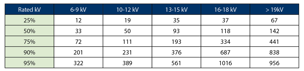
Table 1: Pulse Amplitude (Qm) Distribution for Hydro generators with 80 pF Coupling Capacitors Installed
For example, for 13-15 kV stators in hydro generators and pump-storage units, 25% of tests had a Qm below 35 mV; 50% (the median) had a Qm below 93 mV; 75% were below 193 mV; and 90% of tests yielded a Qm below 376 mV. Thus, if a Qm of 400 mV is obtained on a 13.8 kV hydro generator, it is likely that this stator is deteriorated, since it has PD results higher than 90% of similar machines. In fact, significant stator winding insulation deterioration was observed in over 200 cases where a machine was visually examined after registering a PD level greater than 90 percent of similar machines.
Publishing these results, together with taking the PD trend into account, seems to have reduced the risk of both false positives and false negatives and improved the test’s diagnostic value. An attempt was also made to study the correlation of PD level to visual observation. In 216 cases, PD indicated various failure mechanisms, such as contamination, design and manufacturing problems, and vibration. As a result of a large number of installations using the same type of PD sensor, a standardized data collection approach, and the well-established correlation between PD patterns and insulation condition, PD monitoring identified many pending service problems, prevented a significant number of generator service failures, and has resulted in a major cost saving to the power generation industry.
Detecting Rotor Winding Shorted Turns
Two types of rotors are generally used in synchronous electrical machines: round, for high speed machines, and salient pole for lower speed machines. A turbine generator rotor usually consists of a solid forging made from magnetic alloy steel and copper windings that are assembled in slots machined in the forging. The winding is secured in slots by steel, bronze, or aluminum wedges. At each end of the rotor, the end sections of rotor winding are supported by retaining rings. Modern rotor winding insulations are made mostly from epoxy, polyester glass, or Nomex™ laminate strips and channels. The strips are used to provide inter-turn insulation, and molded channels are used to provide ground insulation. Rotor insulation should be designed to withstand electrical, mechanical, thermal, and environmental stresses.
For moderate and large hydro generators and pumped storage generators, the most common type of salient pole rotor has a strip-on-edge winding on each pole. Such windings are composed of strips of copper that are fabricated around the pole piece much like a picture frame. Electrical insulation, most commonly fiberglass reinforced epoxy, is used to insulate each copper turn from adjacent turns, as well as provide ground insulation between the copper and the rotor pole. Failure of the rotor winding insulation can result in shorted turns. Shorted turns on a rotor may lead to unbalanced magnetic pull, which in turn may cause an increase in bearing vibration. However, shorts can exist with no increase in vibration; thus, bearing vibration is not an infallible way to detect rotor winding aging. The condition of rotor winding insulation is difficult to assess during a shutdown due to limited access and the frequently intermittent nature of faults at operational speed and at standstill. Consequently, on-line testing is a more effective way to detect shorted turns.
Flux Monitoring
Flux monitoring using temporary or permanently installed flux probes on turbine generators has been used since the early 1970s. Flux measurements are used to determine the existence of turn-to-turn shorts in the rotor winding. All of the methods available are based on measuring relatively weak stray flux (rotor slot leakage flux) using flexible or non-flexible polymer-encased stator wedge mounted probes. The stray flux is proportional to the total ampere turns in each rotor slot. If shorts develop between turns in any slot, then the ampere turns in that slot drop, and stray flux across that slot is reduced. The magnitudes of these stray fluxes can be measured using portable or permanently installed instruments, and shorted turns can be identified by comparing the difference in induced voltages from pole to pole. The main challenge in existing technology is the need to manoeuver the turbine generator load to achieve the maximum sensitivity of measurement to every slot of a rotor. This, together with issues including the type of hardware and algorithms used for the detection of shorted turns, has limited the use of this technology in the power industry.
To overcome this problem, new hardware and algorithms were developed in an attempt to make the flux test more sensitive to shorted turns in all coils, even if the generator load could not be changed to align the flux density zero crossing (FDZC) with every slot.
- The temporal and magnitude resolution of the hardware was improved compared to the conventional test.
- Concentration was focused on the main magnetic flux rather than the leakage flux.
- Three proprietary numerical methods were developed to improve the sensitivity to small differences between pole A and pole B main flux plots.
- The results from the three algorithms were compared to develop an index of confidence in the finding of the presence (or not) of shorted turns in each coil.
The new approach can be used with conventional wedge-mounted coils that protrude into the air gap. An alternative probe can be glued to the stator core tooth rather than the stator wedge. This probe directly measures the main magnetic flux that passes through the core tooth. A typical measurement result from a two-pole turbine generator is shown in Figure 1. The grey line indicates the measured signal; the green line measures the integrated signal.
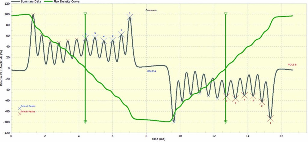
Figure 1: Low-Load Two-Pole Turbine Generator Test Result
The vertical green line indicates the position of FDZC, a point with maximum measurement sensitivity at coil 6 (Figure 1). With load increase, the FDZC will move toward lower number coils, but will never reach coil 1. The measurement result shown in Figure 1 is of very low diagnostic value, since the pole-to-pole difference, per coil, is not visually detectable, so no judgment on the presence of shorted turns can be made. The graph shown in Figure 2 is more useful, but still lacks a clear and easy means to detect the existence of shorted turns.
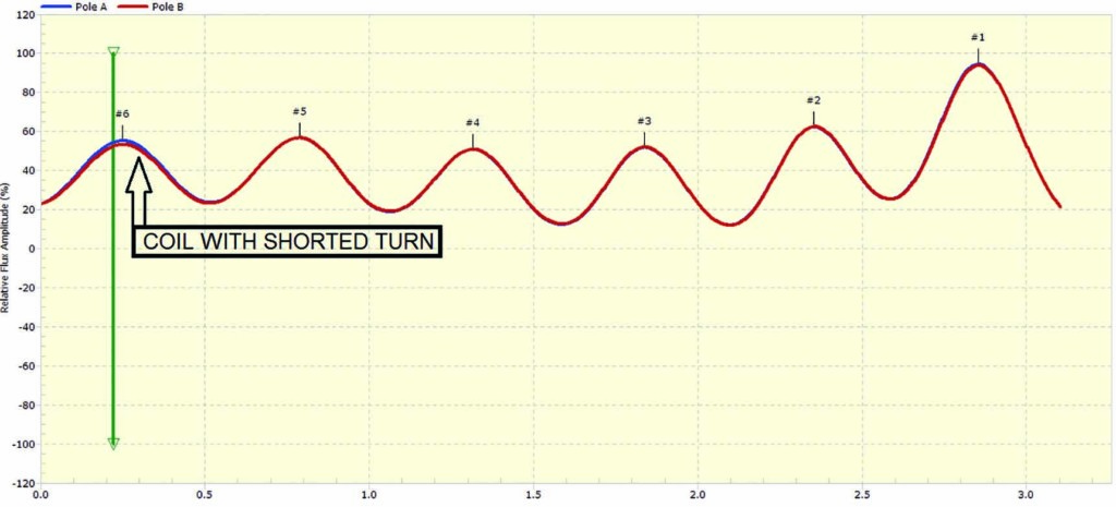
Figure 2: Pole-to-Pole Comparison Indicating Difference in Flux Peak per Coil
Using multiple algorithms resulted in great improvement in analysis reliability, providing measurement results can be used for diagnosis (Figure 3).
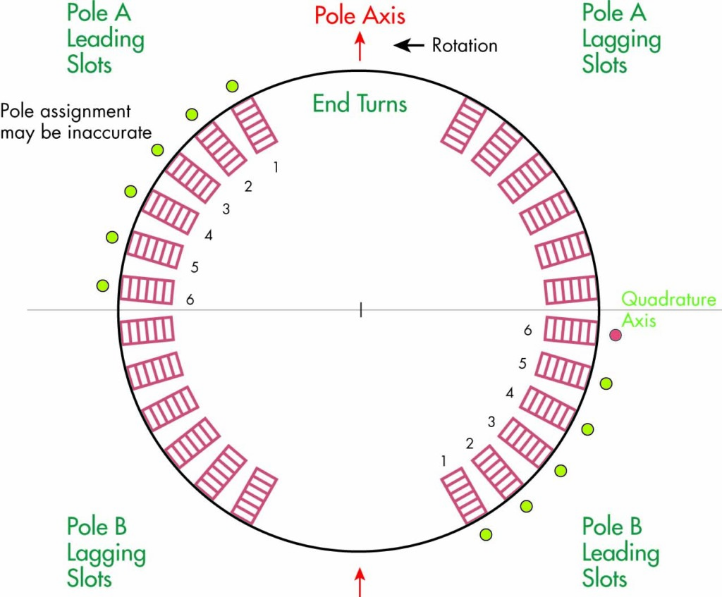
Figure 3: Identification of Pole and Coil with Shorted Turn
Conclusion
Analysing the condition of rotating machines has evolved from off-line testing to a combination of off-line tests and on-line monitoring. No single test is perfect or sufficient to completely diagnose the condition of a rotating machine, and presenting multiple measurement results graphically is frequently more valuable than a simple numerical reading. Further improvement can be gained by combining visual inspection with information from on-line monitors that use multiple technologies, including partial discharge, rotor flux, shaft voltage and current monitoring, and endwinding vibration monitoring.
References
IEEE Std. 1434, IEEE Guide for the Measurement of Partial Discharges in AC Electric Machinery
IEC 60034-27-2, Rotating Electrical Machines – Part 27-2: On-line partial discharge measurements on the stator winding insulation of rotating electrical machines.
G. Stone, “A Perspective on Online Partial Discharge Monitoring for Assessment of the Condition of Rotating Machine Stator Winding Insulation,” IEEE Electrical Insulation Magazine, September/October 2012.
V. Warren, “PD Progress Report,” Iris Rotating Machine Conference, 2015
C. Maughan, “Partial Discharge: A Valuable Stator Winding Evaluation Tool,” IEEE International Symposium on Electrical Insulation, 2006.
D. R. Albright, “Inter turn short-circuit detector for turbine-generator rotor windings,” IEEE Transactions on Power Apparatus and Systems, Vol. PAS-90, No. 2, pp. 478–483, March/April 1971.
M. Šašić, B. Lloyd, A. Elez, “Finite Elements Analysis of Turbine Generator Rotor Winding Shorted Turns,” IEEE Transactions on Energy Conversion, Vol. 27. No. 4, pp 930-937, December 2012.
 Mladen Šašić, PE, IEEE Senior Member, is the manager of Rotating Machines Technical Services with IRIS Power, Canada. He has more than 30 years of experience in the design and testing of high-voltage electrical power equipment. He is an IEEE Senior Member and a registered Professional Engineer in Ontario, Canada. Mladen received a BS in electrical engineering from Sarajevo University, Yugoslavia, in 1987. He coauthored the Handbook of Electrical Motors, which published in 2004, and has written more than 100 technical papers.
 Connor Chan has been a Rotating Machines Engineer at IRIS Power since 2001. He previously was Field Service Manager. Connor received his BS in electrical engineering from the University of Hong Kong. He is a member of IEEE, the Institution of Engineering & Technology (formerly IEE, UK), and the Institution of Engineers Australia, and is a Chartered Engineer.