

Circuit breakers in electrical systems play a critical role in ensuring personnel safety, equipment, and systems reliability. These protective devices are designed to interrupt the flow of electrical current in the event of a fault, preventing potential hazards such as electrical fires and equipment damage.
Low-voltage circuit breakers encompass a range of types, including insulated case circuit breakers (ICCBs)/molded case circuit breakers (MCCB), miniature circuit breakers (MCB), and air circuit breakers (ACB). Each type plays a unique role in electrical systems, and their reliability is paramount for the overall safety and efficiency of the system. In this article, we will discuss low-voltage circuit breakers and explore the significance of primary injection testing in ensuring proper operation and adherence to NFPA 70B and ANSI/NETA standards.
TRIPPING DEVICES
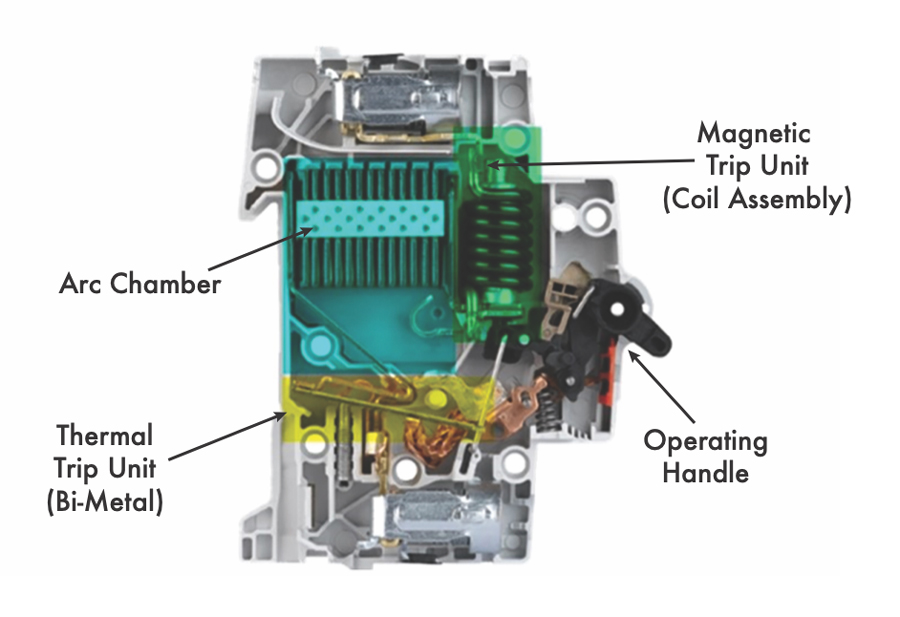
The trip unit within a circuit breaker serves as its brain, responsible for detecting faults and deciding whether to trip or open the operating mechanism in the presence of overload, short-circuit fault conditions, or ground faults. The trip unit can be thermomagnetic or electronic, each offering distinct advantages. Thermomagnetic trip units use bimetallic elements and electromagnets for overload and short-circuit protection, while electronic trip units employ microprocessors for more advanced processing and fault detection (Figure 1).
CONTACT RESISTANCE
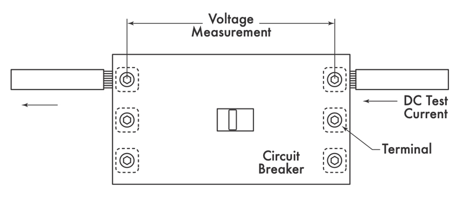
Contact resistance testing (Figure 2) emerges as a mandatory measure in ANSI/NETA ATS and ANSI/NETA MTS standards. Regular testing and monitoring of contact resistance allow maintenance personnel to detect early signs of deterioration or contamination. High contact-resistance values may lead to power dissipation issues, resulting in overheating and faster tripping times in thermal-magnetic circuit breakers.
INSULATION RESISTANCE
Insulation resistance testing is a proactive maintenance measure aimed at evaluating the resistance of insulation material. This test, listed in ANSI/NETA ATS and ANSI/NETA MTS as mandatory before a circuit breaker returns to service, helps identify potential problems by monitoring insulation resistance values over time. A decline in insulation resistance values signals a need for scheduled maintenance and repairs to prevent major issues like insulation failure.
Visual Inspection of Circuit Breakers
Visual inspection of circuit breakers is a critical aspect of electrical maintenance, and it plays a key role in ensuring the safety, reliability, and functionality of electrical systems. NFPA 70B provides maintenance frequency guidelines for electrical equipment as well as visual inspections for circuit breakers.
Before visually inspecting a circuit breaker, follow lockout/tagout procedures to de-energize it and prevent accidental energization. Wear appropriate PPE, including gloves and safety glasses. Thermographic scanning, or infrared thermography, is a valuable non-contact method for detecting temperature variations on electrical equipment surfaces. This technique offers insights into potential issues not easily visible through traditional inspections. Adhering to these inspection practices aligned with NFPA 70B enhances safety, helps identify problems, and contributes to overall electrical system reliability.
PRIMARY INJECTION TESTING
Primary injection testing stands out as a definitive method to validate the performance of circuit breakers. Unlike secondary injection testing, which assesses the electronic trip unit without actual current flow, primary injection testing involves passing high current directly through the breaker to evaluate its performance under realistic conditions. This test is essential for validating long-time, short-time, instantaneous, and ground fault trip settings, detecting mechanical issues, and assessing overall protection.
Long-Time Delay
The long-time delay characteristic is typically associated with direct-acting, low-voltage circuit breakers providing overload protection with time delays of 10–60 seconds at 300% of the pickup rating. The test current is injected through each pole and the trip time is recorded each time. The results are then compared to the time current curves or TCCs provided by the manufacturer. Long-time (overload) protects against a small increase in current above full load amperes over a longer period of time.
Short-Time Delay
The short-time delay characteristic provides protection for short circuit or fault conditions. It is utilized whenever a small delay is required for coordination or selectivity with other protective devices. Typical delays of this characteristic are approximately 6–30 cycles. The test current is injected at 1.5–2.5 times the short-time pickup through each pole of the breaker, and the trip time is recorded. The results are validated by referring to the time-current curves published by the manufacturer.
I²T IN will result in an inverse-time delay that resembles the time/current characteristics of fuses, which is similar to a long-time function except with a much faster delay.
I²T OUT provides a constant delay, usually 0.5 seconds or less as noted on the time-current curve.
Instantaneous Trip
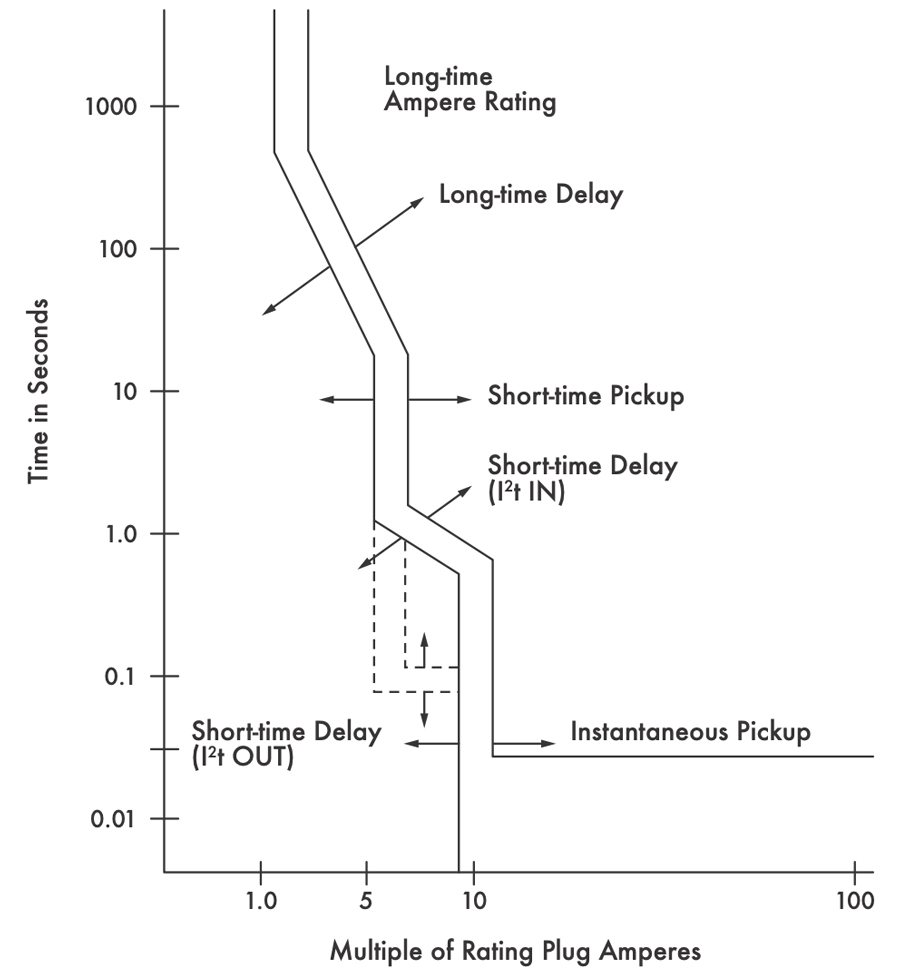
The instantaneous trip characteristic (Figure 3) is used for short circuit or fault protection and has no intentional time delay. It is the minimum level of current at which the circuit breaker’s tripping mechanism is designed to activate instantaneously. In this test, the starting current is pulsed around 70% of the pickup and is steadily increased through each pole of the circuit breaker in a duration of 5 to 10 cycles since an instantaneous trip should typically be shorter than 5 to 8 cycles. Once the breaker trips, the current and time are recorded. A real-world instantaneous trip example would be to connect a power source to ground instead of to the point where it should be connected. This would cause an extreme fault with zero impedance, thus giving the maximum prospective short-circuit current in the faulted circuit.
GROUND FAULT PROTECTION
Before primary injection testing the phase protection elements of circuit breakers with ground fault protection, ensure the ground fault protection is disabled. High currents during testing can trigger the active ground fault protection, causing the breaker to trip on the ground fault function instead of the function being tested. If the breaker lacks an option to disable ground fault protection, current can be injected through one pole connected in series with the other two poles to validate the trip test on a specific pole (Figure 4).
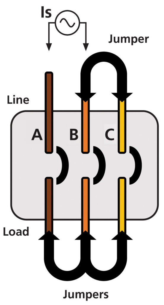
Figure 4: Primary Injection Looping Method
Ground Fault Pickup
Ground fault pickup defines the threshold current level at which the circuit breaker’s protective mechanism is triggered in response to a ground fault. The ground fault pickup setting is typically a fraction, usually ranging from 20% to 60% of the continuous current rating of the overcurrent protection device. In this test, the injected test current is typically set at 1.5–2.5 times the pickup value. This test is required for numerous service entrances according to NFPA 70B and NFPA 70, National Electrical Code (NEC) 230.95.
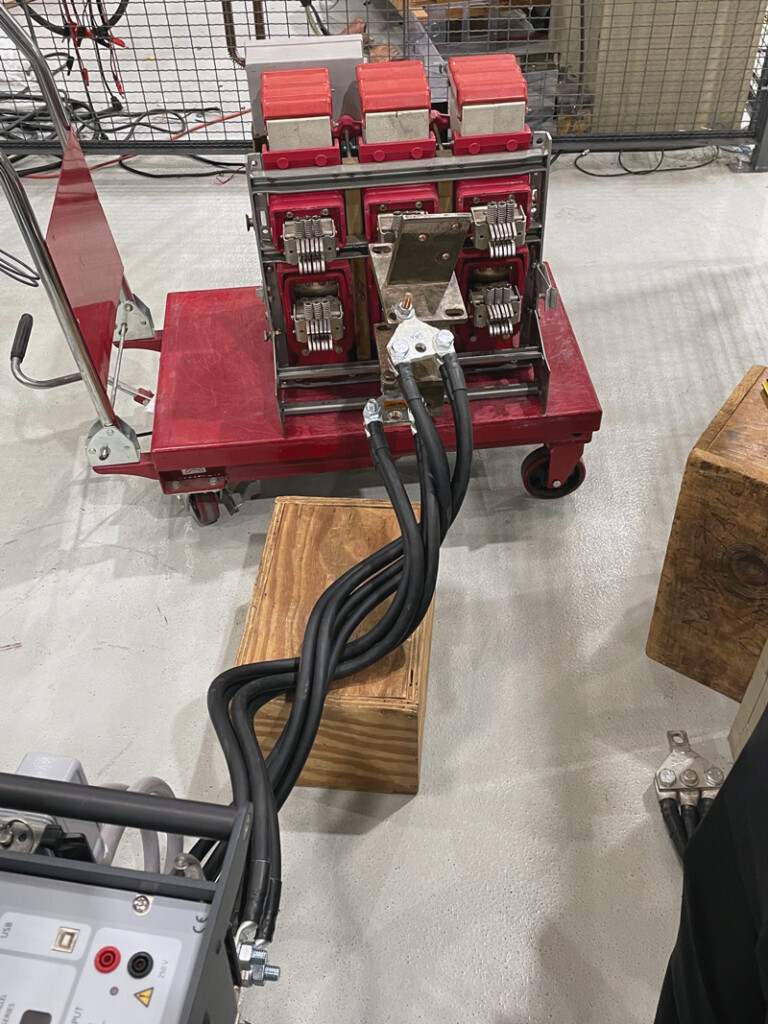
Primary Injection Test Connections
Accurate test connections are crucial for primary injection testing, where high currents are injected directly into circuit breakers. Loose or improper connections can lead to inaccuracies in test results and pose electrical hazards. Best practices include using high-quality cables and connectors, cleaning and inspecting connections before testing, ensuring tight connections, and minimizing cable length for reduced resistance and voltage drop. Cables of opposing currents can be twisted together (Figure 5) over the length of the cable to minimize the reactance.
The primary injection test set acts as a current source and limitations become evident when there is an impedance within the test circuit. Consequently, this impedance, along with the associated voltage drop, places a load on the instrument. If the load or burden becomes too substantial, the current source cannot deliver the required current effectively. Therefore, it is of the utmost importance for field personnel to optimize the setup meticulously. A poorly configured setup can result in a significant reduction in the output capabilities of a primary injection test set.
UNDERSTANDING TIME CURRENT CURVES
In this example, using Figure 6’s trip curve with a 50-ampere trip unit, we observe time-current curves depicting the minimum and maximum times the breaker will trip at various current levels. These curves, provided by the breaker or trip unit manufacturer, use the horizontal axis for multiples of rated current or current in amperes and the vertical axis for time in seconds. To determine trip time at a specific current, trace a vertical line from the current level to where it intersects the curve, then draw a horizontal line to the left side. Many modern primary injection test sets include built-in trip curve libraries, reducing error in result analysis.
Overload Protection Component of the Time Current Curve
In Figure 6, the circuit breaker trips at 300% of the pick-up rating, taking between 7 and 15 seconds. Higher currents lead to shorter operating times. Time-current curves appear as bands within the circuit breaker’s bimetallic strip, connected in series with the load, expanding and bending as the current exceeds its rating. This expansion triggers the trip mechanism, opening the breaker contacts.
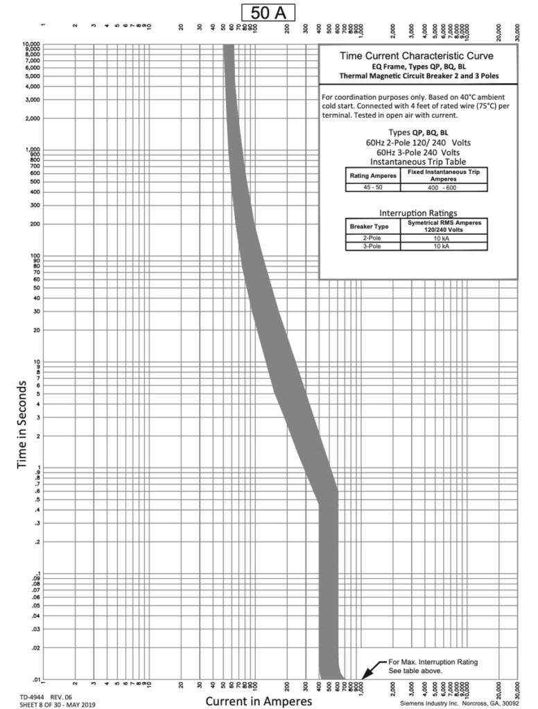
Instantaneous Trip Component of the Time Current Curve
The bottom part of the time-current curve in Figure 6 shows the performance of the instantaneous trip component of the circuit breaker. Referencing Csanyi: “The maximum amount of time it takes for the breaker to completely open decreases as the current increases. This is due to the blow-apart design of the contacts, which utilizes the magnetic field built up around the contacts. As current increases, so does the magnetic field, which aids in opening the breaker contacts.”[3]
This circuit breaker has an adjustable trip point from 400 A to 600 A, which is 8–12 times the trip unit rating. If the trip point adjustment is set to a minimum of 400 A, and a fault current of 400 A or greater occurs, the breaker will trip within 1 cycle (16.8 ms).
CONCLUSION
Maintenance and testing of low-voltage circuit breakers are vital aspects of ensuring the safety, reliability, and longevity of electrical systems. Recent studies by Hartford Insurance Company and NETA have shown that circuit breakers have a failure rate of over 15%. Defective breakers can cause extensive damage and personal injury, trip when they should not, and make outages worse in the event of a fault.
The various testing methods discussed, including contact resistance testing, insulation resistance testing, visual inspection, and primary injection testing in accordance with ANSI/NETA standards and guidelines, all play essential roles in evaluating and maintaining circuit breaker performance.
- Contact resistance testing helps identify early signs of deterioration or contamination in the main contacts, enabling timely maintenance to prevent potential failures.
- Insulation resistance testing ensures the integrity of insulation materials, safeguarding against electrical faults and aiding in scheduled maintenance before significant issues arise.
- Primary injection testing, a comprehensive and realistic evaluation method, validates circuit breaker performance under fault conditions, including long-time, short-time, instantaneous, and ground fault settings. It helps detect mechanical issues, assess protection, and ensure coordination with other protective devices.
- Proper test connections, considering breaker age and operation history, and understanding time-current curves are crucial elements for accurate and reliable testing.
- Understanding the significance of disabling ground fault protection before primary injection testing is essential; if the option to disable it is not available, the looping method should be performed.
By adhering to industry standards and best practices, professionals can ensure that circuit breakers continue to fulfill their critical role in protecting personnel and equipment from electrical hazards. Regular testing and maintenance, coupled with an understanding of circuit breaker characteristics, help maintain the integrity of electrical systems, promoting their long-term performance and safety.
REFERENCES
[1] Bolar, Sanket. “Primary Injection Testing on Low-Voltage Circuit Breakers.” NETA World, Spring 2021. Available at www.netaworldjournal.org/primary-injection-testing-on-low-voltage-circuit-breakers. [2] ANSI/NETA MTS–2023, Standard for Maintenance Testing Specifications for Electrical Power Equipment and Systems, 20 June 2023. [3] Csanyi, Edvard. “Time-Current Curves Explained in Details.” Electrical Engineering Portal (EEP), 7 Dec. 2010, www.electrical-engineering-portal.com/time-current-curves. [4] Parmar, Jignesh. “Type of Tripping Mechanism of MCB/MCCB–(Part 1).” Electrical Notes & Articles; 1 Mar. 2017. Available at https://electricalnotes.wpcomstaging.com/2017/03/01/type-of-tripping-mechanism-of-mcb-mccb-part-1/. [5] TestGuy. “Characteristics of Circuit Breaker Trip Curves and Coordination.” TestGuy Electrical Testing Network, 17 May 2015. Available at https://wiki.testguy.net/t/characteristics-of-circuit-breaker-trip-curves-and-coordination/112. [6] GE Energy. Power Break II Insulated Case Circuit Breakers. GE Energy, 2011. [7] National Electrical Manufacturers Association. NEMA AB 4–2017, Guidelines for Inspection and Preventative Maintenance of Molded Case Circuit Breakers Used in Commercial and Industrial Applications, 2017. [8] NFPA Electrical Equipment Maintenance Committee. “NFPA 70B, Standard for Electrical Equipment Maintenance.” NFPA Link®, National Fire Protection Association, 2023, www.link.nfpa.org/free-access/publications/70B/2023.
Cade Patton is an Applications Engineer for Megger in the Substation Technical Support Group where his primary focus is on electrical testing. Cade earned his BS in electrical engineering from Texas A&M University at Commerce in 2022.