

Along the extensive and complex electrical system infrastructure from generation to transmission and distribution, the wide variety of medium- and high-voltage circuit breakers (MV/HV CB) vary in size, interrupting medium, number of breaks per phase, and various other attributes. To help classify breakers and their attributes, they are all shipped with a nameplate stating the minimum information about specific mechanical, physical, and electrical characteristics that is required by IEEE Std. C37.04. Although manufacturers are only required to provide the minimum information, some provide more detailed information than others.
Viewing the nameplate will yield a variety of information concerning the CB’s function, electrical characteristics, and expected performance. For example, the same breaker may have different types of operating mechanisms, and this might not be apparent when first looking at the nameplate. Further investigation would be needed to fully understand the breaker’s mechanism specifications.
Understanding the information provided on the nameplate will provide a general description of the CB’s mechanism and operating conditions. Since there are many types of CBs, as well as numerous manufacturers, several questions can provide helpful information:
- Do all nameplates provide the same information?
- What is the minimum information that must be stated on the nameplate?
- One important specification on the nameplate is interrupting time. Does this correlate to operating times measured while testing?
- Will a quick glance at the nameplate tell you everything you need to test on the CB and what the expected values are?
This article focuses on the HV/MV CB nameplate information that is necessary for testing purposes. IEEE nameplate requirements and definitions are discussed. Parameters that are commonly tested in the field are described along with whether the parameter is verified or measured during the design, factory, or field phase of the breaker’s life cycle, and additional testing of parameters not shown on the nameplate is recommended. In the end, the reader will have a basic understanding of the CB nameplate and how it relates to the application, operation, and maintenance of the CB.
NAMEPLATE REQUIREMENTS
At a minimum, the CB nameplate will indicate the attributes of the CB and its mechanism. The manufacturer can choose to combine these into a single nameplate or provide separate nameplates. This article focuses only on the nameplates containing the attributes of the CB and the mechanism. However, certain additional nameplates are also required:
- Nameplates must describe the operating characteristics of any current transformers (CT) or linear coupler transformers attached to the CB.
- A nameplate indicating dielectric withstand capability must be provided for any self-contained components, such as current transformers (CTs) or bushings; this information could also be included on the CB nameplate.
- Nameplates must be provided for any attached accessories indicating what they are, as well as any operating characteristics or relevant information.
Figure 1 and Figure 2 show examples of separate and combined CB nameplate configurations.
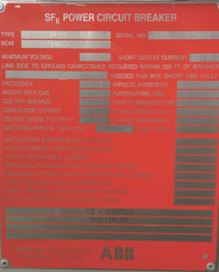
Figure 1a: Separate Nameplates for CB
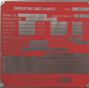
Figure 1b: Separate Nameplates for Mechanism
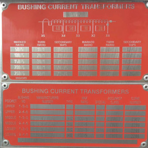
Figure 1c: Separate Nameplates for CT
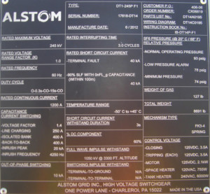
Figure 2: Combination CB and Mechanism Nameplate
The information required on the CB nameplate can be divided into four categories:
- Documentation provides general data identifying the CB manufacturer, CB type, serial number, and year of manufacture along with a parts list and the instruction book number.
- Physical characteristics listed on the nameplate describe the CB’s weight, operating pressure, and the volume of oil or weight of gas inside the tank.
- Electrical characteristics provide the general operating conditions of the CB along with insulation levels and other protection information.
- Operating characteristics refer to the minimum and/or maximum conditions for the mechanism to be able to operate and might include some electrical parameters related to the control of the breaker. In cases where the mechanism is hydraulic or pneumatic, the nameplate will show pressure rather than electrical parameters.
Table 1 and Table 2 provide the minimum CB and mechanism nameplate data required by IEEE Std. C37.04.
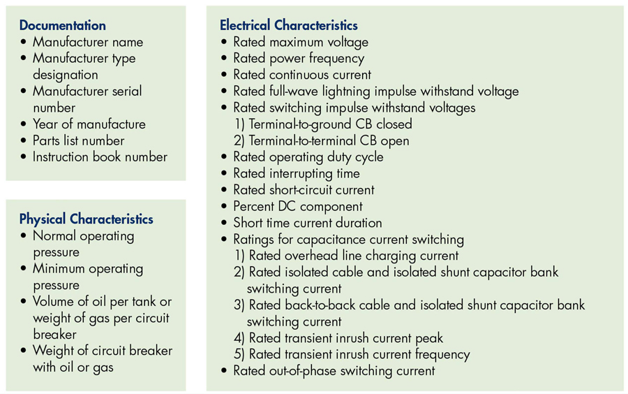
Table 1: IEEE Std. C37.04 Minimum CB Nameplate Data
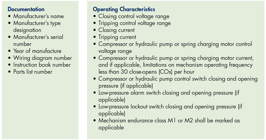
Table 2: IEEE Std. C37.04 Minimum Mechanism Nameplate Data
CB ELECTRICAL AND OPERATING CHARACTERISTICS
CB characteristics include documentation, physical characteristics, and electrical characteristics. and operating characteristics.
Rated Maximum Voltage
IEEE Std. 37.04–2018 states:
The rated maximum voltage of a circuit breaker is the highest rms phase-to-phase voltage for which the circuit breaker is designed, and is the upper limit for operation.
When the nameplate refers to continuous current and short-circuit current, it is the current at this rated maximum voltage.
A design test performing short-circuit current interruption and other current switching rating tests at the rated maximum voltage is used to verify this characteristic.
Rated Power Frequency
This is the frequency at which the CB is designed to operate. Typically, this frequency is 60 Hz or 50 Hz, but other frequencies exist (e.g., 25 Hz or 16-2/3 Hz). If the CB is operated at a higher frequency than its intended design, the CB will need to be de-rated, and the manufacturer should be contacted for consultation.
Rated Continuous Current
The rated continuous current is the maximum RMS current at rated power frequency that the CB can transmit continuously during usual service conditions (see IEEE Std. C37.04–2018 Section 5.5). The current ratings are designed around the temperature limits of all the parts used to construct the CB. The CB is designed to carry this current at an ambient temperature of 40°C. For the maximum internal temperatures of the individual components, see IEEE Std. C37.04–2018 Section 5.5.2. The rated continuous current is applicable at or below the rated maximum voltage.
Rated Full-Wave Lightning Impulse Withstand Voltage
Although the CB is designed to operate at a rated maximum voltage, it may be subject to environmental conditions that exceed the maximum voltage. The dielectric withstand capability of a CB is demonstrated by subjecting it to a power frequency, a lightning impulse test, and where required, a chopped-wave lightning impulse and switching impulse test at voltage levels equal to or greater than those specified in ANSI C37.06, Trial-Use Guide for High-Voltage Circuit Breakers Rated on a Symmetrical Current.
IEEE Std. 4–2013 Section 8 defines the standard lightning impulse as:
A full lightning impulse having a front time of (T1) of 1.2 and value (T2) of 50, and is described as a 1.2/50 impulse. The rated full-wave lightning impulse withstand voltage is the peak value of this wave. A new CB must have a 10% or less chance of external flashover when subjected to this wave.
Rated Switching-Impulse Withstand Voltages
In addition to the lightning impulse rating, CBs rated at 362 kV and above are assigned a switching-impulse withstand voltage rating. These CBs can be subjected to transient overvoltages when they are switching open or loaded, or when faulted lines and equipment are present. To help alleviate these overvoltages, the CB are often equipped with pre-insertion resistors (PIR) or synchronous closing devices.
Rated switching-impulse withstand voltage is the voltage value at the peak of a standard 250 x 2500 switching-impulse wave (IEEE Std. 4–1995 Section 8) where 250 is the time to peak value and 2500 is the time to reach half-peak value. At this voltage value, the CB has a 10% or less probability of external flashover to ground in both wet and dry conditions.
Operating Duty Cycle
Also known as the rated operating sequence or rated standard operating duty, the operating duty cycle is a predefined sequence of operations in a specific period and interval. The sequence, period, and interval may be defined by industry standards, the manufacturer, or specific applications.
Per IEEE Std. C37.04, the standard operating duty of a CB is:
O – t – CO – t’- CO
where:
O is Open
CO is Close-Open
t’ is 3 minutes
t is the minimum reclosing time
For CBs not rated for rapid reclosing, t is 15 s and 0.3 s for CBs rated for rapid reclosing duty.
In generator CBs, IEEE Std. C37.013 specifies that the rated short-circuit duty cycle shall be two operations with a 30-min interval between operations (CO–30 min–CO). In circuit switchers (IEEE Std. C37.016), the rated operating sequence is Close-Open (CO).
The sequence of operations shown on the nameplate is the maximum number of operations in a specific period that the breaker was designed for. This should not be exceeded in the regular operation of the breaker or during field testing. It is also an indication of what type of application the breaker is designed to handle.
The minimum operation a breaker should be capable of performing is the CO, and it is the sequence the breaker should follow when the breaker is requested to close but there is already a trip command from a fault in the system. The breaker should close completely and then open immediately. This is also a basic sequence that any breaker is designed and built to perform.
The reclose sequence OC is the capability of the breaker to clear a fault and close after a delay. Some applications, e.g., generator breakers in which the breaker might not be mechanically designed for this sequence, do not require this. It should not be simulated during testing, as it may break or get jammed.
When a CB is designed for the reclose function, it should also be capable of opening immediately after a reclose to interrupt the fault if the fault is still present after the first clearing attempt. This sequence of operation is known as the OCO, although it is not commonly tested.
It is important to test the sequence defined in the nameplate to verify that the breaker will be capable of performing as per the design, especially if the sequence is being fully used in the system, for example, the reclose function instead of just an open and close operation.
Rated Interrupting Time
This is the manufacturer’s designated operating time limit for the opening of the contacts and interruption of the arc during the clearing of a fault. Rated interrupting time is measured from the energization of the trip circuit at rated voltage until the total interruption of current flow through the contacts. This interval includes the operation of the trip coil, actuation of the mechanism (travel), contact part separation, and extinguishing of the arc in all poles. This time depends on the speed of the breaker.
The standard rated interrupting time for CBs is 2, 3, or 5 cycles, but this might be exceeded under certain applications. In a CO operation, the interrupting time should not be more than 1 cycle for 5-cycle or higher CBs and ½ cycle for 3-cycle CBs. For out-of-phase switching, the time can be exceeded by 50% in 5-cycle CBs and 1 cycle in 3-cycle or faster CBs. In generator CBs, the typical values are between 60 ms and 90 ms.
This parameter is important during the design of the electrical network, especially when considering system stability and determining expected clearing times. The rated interrupting time is the main component of the total time it takes to clear a fault from its initiation to relay pickup and eventually arc extinction.
Rated Short-Circuit Current
This is the highest symmetrical component of short-circuit rms current at the instant of arcing contact separation that a breaker should interrupt at rated maximum voltage and standard operating duty without suffering damage of any nature in any of its components. This current includes the DC component, and it also establishes by fixed ratios the highest currents that the CB can close and latch against to carry and to interrupt.
ANSI C37.06 defines the preferred short-circuit current ratings for 123 kV and above CBs as ranging from 31.5 kA to 80 kA. The typical values for generator CBs range from 63 kA to 160 kA as per IEEE Std. C37.013. These types of CBs are required to close in on a fault, latch, and carry current for at least 0.25 s. The peak making current should not exceed 2.74 times the rated short-circuit current. This parameter is tested only at the factory.
Percent DC Component
This defines the portion of the total DC current that the breaker is capable of interrupting during an asymmetrical fault. It is an important parameter for CB specification and relay setting calculations. This specification cannot be verified in the field.
Short-Time Current Duration
This is the maximum time a CB can carry the rated short-circuit current without any damage. It is the maximum permissible tripping time delay (Y) for CBs.
The standards indicate a duration of 1 s for HVCBs 123 kV and above, for circuit switchers above 72 kV, and for generator CBs. However, it is common to see breakers with a specification of 3 s.
Ratings for Capacitance Current Switching
Capacitive currents are present during the switching of no-load overhead lines, no-load cables, capacitor banks, or filter banks. Energization of parallel capacitor banks and no-load lines can generate overvoltages or high currents, whereas the interruption of capacitive currents can generate voltage breakdowns across contact separation, known as re-ignition (less than ¼ of a cycle) and restrike (greater than ¼ of a cycle). Re-ignition can generate power-quality problems, while restrike will cause overvoltages of up to three times the peak value of the phase-to-ground voltage across the capacitive load for each restrike.
Breakers are designed to handle a certain amount of capacitive current under different system conditions like overhead line switching, isolated cable and isolated shunt-capacitor-bank switching, back-to-back cable and isolated shunt-capacitor-bank switching current, transient inrush current peak, and transient inrush current frequency. IEEE Std. C37.06 shows the preferred capacitance current switching ratings for indoor and outdoor CBs. This characteristic is tested at the factory, and IEEE Std. C37.09 and IEEE Std. C37.012 specify the proper procedures for testing.
Each capacitive current switching rating assigned to the breaker must have an associated class from the following categories:
- Class C0: Unspecified probability of restrike during capacitive current breaking. Capability for one restrike per operation
- Class C1: Low probability of restrike while breaking capacitive current
- Class C2: Very-low probability of restrike while breaking capacitive current
Rated Out-of-Phase Switching Current
The out-of-phase condition is an abnormal situation in which the synchronism on either side of the CB is lost, creating a difference of potential where the phase angle of the voltages exceeds the normal values. In some cases, the voltages can be 180° out of phase. During out-of-phase switching conditions, a very large short-circuit current occurs.
The rated out-of-phase switching current is the current that the breaker should be capable of handling during an operation under a lack of synchronism. This is an uncommon situation, so not all breakers are designed for this. Whenever a breaker is designed with this capability, the preferred rating is 25% of the rated (symmetrical) short-circuit current expressed in kA, and the interrupting time is allowed to be greater than the rated interrupting time by 50% for 5-cycle breakers and by 1 cycle for 3-cycle breakers.
CB MECHANISM CHARACTERISTICS
Mechanism characteristics include documentation and operating characteristics.
Control Voltage Range
This is the designated control voltage range required for operation of the mechanism at the connecting point of the control circuit. The high end of the range corresponds to the open-circuit voltage. The low end of the range corresponds to the voltage when the maximum operating current is flowing through the control circuit. The control circuit includes operating coils, auxiliary relays, and compressor, hydraulic pump, or spring charging motor.
IEEE Std. C37.06–2009 defines various ranges based on DC/AC signals, indoor or outdoor applications, and closing/tripping operations. For a DC voltage, various ranges are defined from 24 V to 250 V. Ranges below 48 V are not recommended for breakers that might experience a voltage drop during operation, such as being far from the source or where the cabling is not adequate.
Control Current
This is the maximum current at nominal voltage that should flow through the control circuit during the operation of the CB. Each element in the control circuit has its own nominal current and maximum current.
In some cases, e.g., in the tripping coil or the spring-charging motor, a characteristic current curve provides valuable information on the condition of the element or its associated part of the mechanism. For example, the tripping-coil current reveals information on the condition of the latching system, and the spring-charging motor current indicates the condition of the spring mechanism.
Rated Operating Pressures
CBs might require pressurized systems for hydraulic or pneumatically operated mechanisms and/or for interrupters that use a pressurized gas as the interrupting medium. Each of these has a rated pressure range as per the CB design and construction that should be guaranteed at any time for the breaker to be operated safely.
The pressure refers to the standard atmospheric air conditions of +20°C and 101.3 kPa (absolute)(or density), which may be expressed in relative or absolute terms, to which the mechanism or the interruption chamber should be filled before being operated.
CONCLUSION
CB nameplates contain basic information on how a breaker was designed and built, and it is useful to many different audiences. System engineers and operators use nameplate information for system calculations and to determine appropriate applications of the CB. System installers use it to verify conditions prior to installation. Testing and commissioning personnel use it to properly prepare testing procedures and evaluation criteria. Although the information displayed on the nameplate might not be complete for every audience’s need, especially for field testing purposes, most of the information is in the CB manual or instruction book, which is referenced on the nameplate.
For information on testing procedures that can confirm the expected performance of the CB, watch for Part 2 of this article in the Spring issue of NETA World.
REFERENCES
IEEE Std 4–2013, IEEE Standard Techniques for High-Voltage Testing.
IEEE Std 100–2000, The Authoritative Dictionary of IEEE Standard Terms – Seventh Edition.
IEEE C37.04–2018, IEEE Standard Rating Structure for AC High-Voltage Circuit Breakers.
IEEE C37.06–2009, IEEE Standard for AC High-Voltage Circuit Breakers Rated on a Symmetrical Current Basis – Preferred Ratings and Related Required Capabilities for Voltages Above 1000 V.
IEEE C37.09–1999, IEEE Standard Test Procedure for AC High-Voltage Circuit Breakers Rated on a Symmetrical Current Basis.
IEEE C37.010–1999, IEEE Application Guide for AC High-Voltage Circuit Breakers Rated on a Symmetrical Current Basis.
IEEE C37.012–2005, IEEE Application Guide for Capacitance Current Switching for AC High-Voltage Circuit Breakers.
IEEE C37.013–1997, IEEE Standard for AC High-Voltage Generator Circuit Breakers Rated on a Symmetrical Current Basis.
IEEE C37.016–2006, IEEE Standard for AC High-Voltage Circuit Switchers Rated 15.5 kV through 245 kV.
 Volney Naranjo joined the Technical Support Group at Megger in 2011 as an Applications Engineer focusing on the products for transformer, low-voltage and high-voltage circuit breakers, batteries, and power quality testing. He participates in the IEEE Energy Storage and Stationary Battery committee and has published articles in conferences such as TechCon, PowerTest, TSDOS, BattCon, and EIC as well as technical magazines. Volney received his BSEE from Universidad del Valle in Cali, Colombia. After graduation, he worked in the areas of electrical design and testing and commissioning of power systems as a field engineer and project manager.