

Rapid photovoltaic (PV) penetration into the electric grid has mandated deeper operational and technical understanding of protection schemes in PV farms. An effective protection scheme ensures a grid-connected system functions reliably and securely, and testing and commissioning the entire protection scheme to prove its operational success is of paramount importance. This article presents a standard grid-tie photovoltaic farm architecture and discusses how to restore the system to regular operation using reclosing schemes.
Distributed generation (DG) is increasingly widespread across the nation’s utility landscape, but uniform policies that allow renewable energy generators to connect to the utility grid were missing until recently. This significantly complicates renewable energy installations and has likely deterred the adoption of customer-sited DG. To address these complications, IEEE introduced interconnection standard IEEE Std. 1547 in 2003 to facilitate deployment of renewables and other forms of DG by specifying technical and institutional requirements and the terms by which utilities and DG system owners must abide.
IEEE and North American Reliability Corporation (NERC) standards exist to address the reliability needs of interconnected electricity systems. These standards apply to the bulk electrical system (BES) specified by the BES definition adopted by the Federal Energy Regulatory Commission (FERC) in March 2014.
In some cases, norms apply to devices and needs beyond the BES. As more distributed energy resources are connected to the grid, their impact on the bulk power system is becoming substantial. At higher penetration levels, issues may develop in transmission line loading, grid voltage, and system frequency during regular or disturbed operation. Therefore, extensive testing and commissioning of devices that are part of distributed generation and their interconnection have gained careful consideration. This article looks at protection testing of recloser controllers that are a crucial part of many grid-tied renewable energy systems.
System Description
A typical utility-scale solar photovoltaic system is shown in Figure 1. The system is divided into three subsystems: direct current system, alternate current collector system, and distribution-level system.
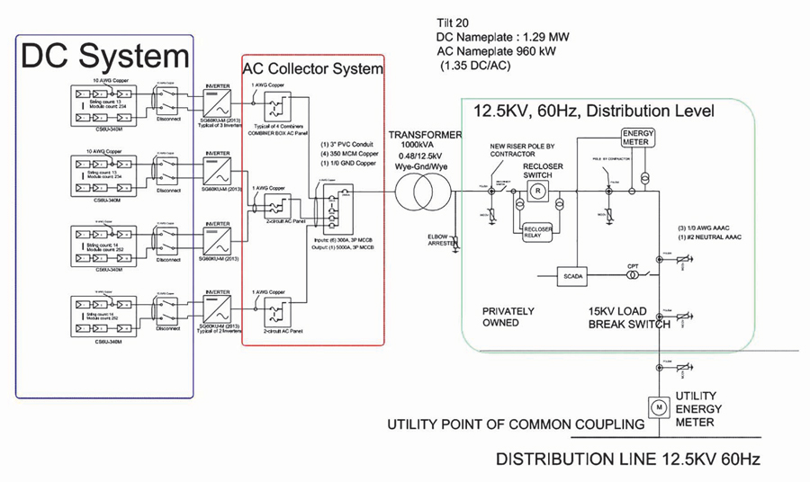
Figure 1: One-Line Diagram for Utility-Scale Solar Farm Main Zones
- The direct current system consists of solar arrays, combiner boxes, fuses, and disconnects all operating on DC power. Each subsystem’s specific overcurrent protection needs are based on the requirements of array-combiner boxes.
- The alternate current collector system is located on the AC side of the inverter and typically consists of a 480 V AC common bus.
- The distribution-level system appears at the output of the collector system. Power from the solar farm is injected via a step-up transformer, which transforms system voltage from 480 V AC to 12.5 KV AC allowing interconnection to distribution line voltages. This subsystem consists of potential transformers (PTs), current transformers (CTs), medium-voltage underground and overhead cable, a revenue meter, and a medium-voltage recloser switch equipped with an electronic relay.
Inverters in the solar farm transform energy from DC to AC. Each inverter has overcurrent and overvoltage protection. The DC protection side is isolated from the AC side, including isolated ground fault systems. Indeed, individual protection schemes apply to each subsystem. However, this paper focuses on protection requirements for the distribution-level system.
Interconnection and Protection
IEEE Std. 1547-2018 describes the requirements for interconnecting solar PV farms. A photovoltaic solar farm classifies as a distributed energy resource (DER) and therefore must comply with operational requirements to respond to abnormal voltages and frequency events in the utility line.
Conditions for interconnection include active and reactive power capability and voltage/power requirements. The three-phase inverters are responsible for adjusting these in the system. The inverters act as a link between the DC system and the AC collector system as shown in Figure 1.
Figure 2, a detailed view of the distribution level system, indicates the location of the recloser switch and relay.
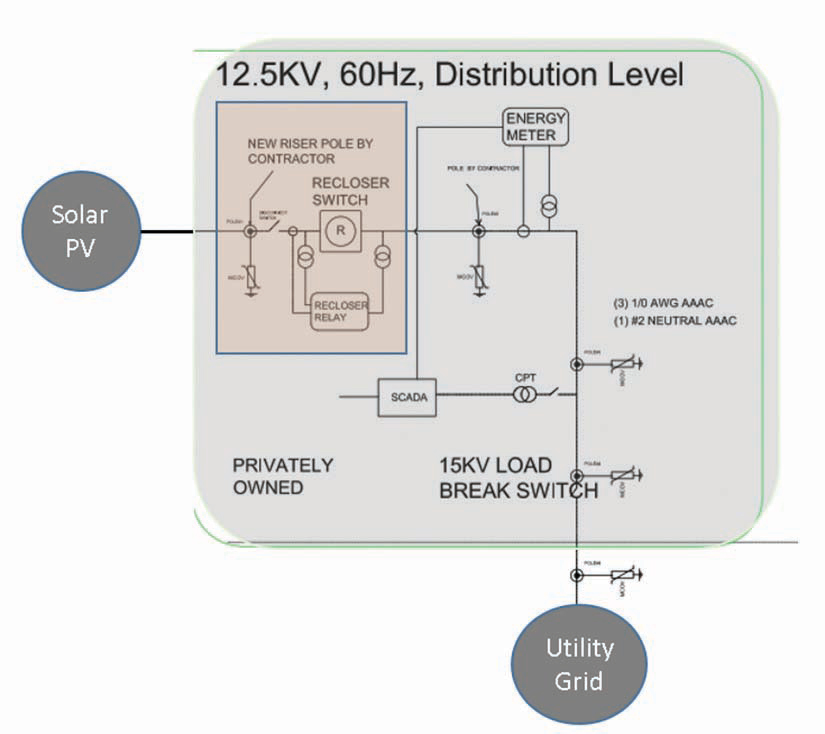
Figure 2: Distribution Level System for Solar PV Interconnection
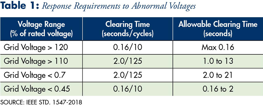
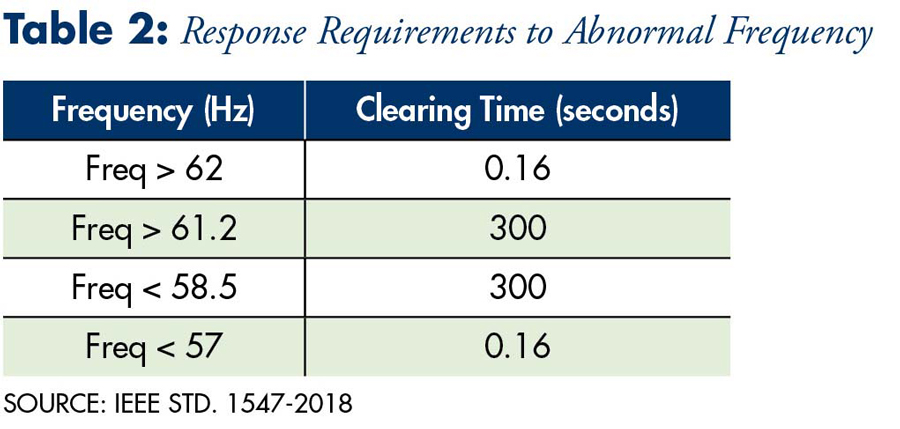
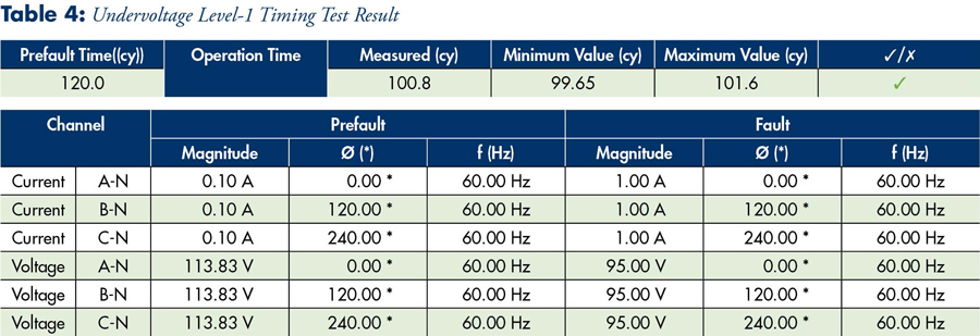
The MV recloser and its relay system should respond to utility EPS disturbances. IEEE Std. 1547 establishes response-time requirements for mandatory disconnection due to loss of phase, area EPS fault conditions, and out of limit voltage or frequency. Table 1 and Table 2 indicate boundaries for voltage and frequency, respectively.
During fault conditions, grid voltage (line side of the recloser switch) could experience excursions outside of normal operating values resulting in power fluctuations. Therefore, the standard recommends two levels of undervoltage and overvoltage. To comply, system voltage on the utility side of the recloser must be monitored. The MV recloser switch controller chosen for this article is capable of receiving six voltage inputs. Three inputs are from the utility side, sourced from three 0.5 kVA distribution transformers; three inputs are from the generating side, sourced from three low-energy capacitive voltage sensors located in the bushings of the solid dielectric recloser.
The standard also proposes underfrequency and overfrequency levels that directly address the system’s protection stability and are indirectly responsible for unintentional islanding.
When an MV recloser switch operates and isolates a PV farm from the grid, a relay mechanism must guarantee reconnection once grid conditions are normal and healthy voltage is established. Schemes involving automatic reclosing (Figure 3) can ensure proper disconnection and reconnection of the solar PV farm to maintain production while the solar PV injects the maximum power available. The recloser sequence should be coordinated with the local area EPS since automatic reclosing onto a circuit needs approval from the affected utility. Abnormal conditions should result in momentary cessation of operating mode, and restoration of connection behavior must be coordinated for proper reclosing time characteristics.
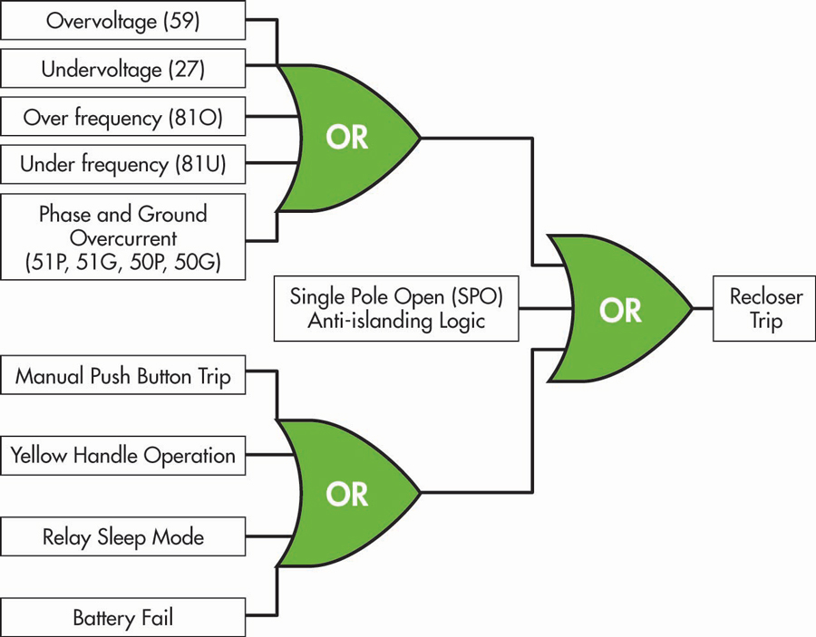
Figure 3: MV Recloser Switch Relay Trip Conditions
External conditions such as battery failure, manual push-button trip, yellow-handle operation, and relay sleep mode must be considered in the MV reclosing sequence.
Testing and Commissioning
For reliable operation of an interconnected system, testing and commissioning protection elements for the MV recloser switch must be performed with satisfactory results.
Functional Tests
Functional tests include testing individual protective elements that are used in the logic of the MV recloser switch controller for interconnection requirements. The microprocessor-based controller under test can accommodate two-phase voltage: one phase current and one neutral current winding. It is also capable of functioning as either a single-pole or three-pole trip and close for reclosing applications.
- Undervoltage/Overvoltage Elements. Two undervoltage and overvoltage elements are set in phase-to-neutral (Ph-N) volts secondary. Time delays are set in units of cycles (Figure 4). Any modern relay test equipment that can provide three-phase voltages can be used.
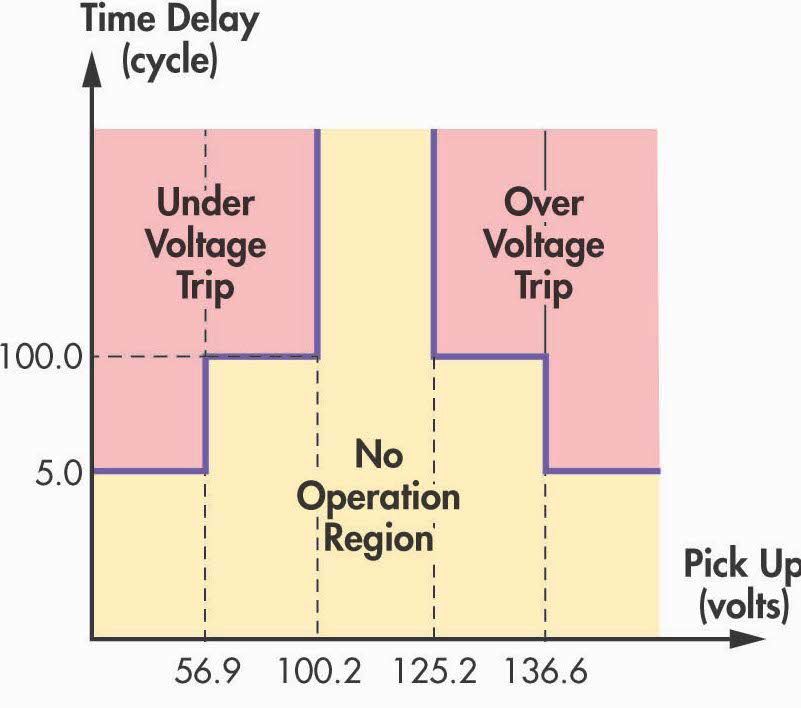
Figure 4: Voltage Element Settings
- Pickup Test. Figure 5 shows that the pickup test can be designed using step-ramp decrements with nominal secondary voltage as a pre-fault condition. The start of the ramp can be set to 110% of the expected level-1 pickup (100.2 V) value and the stop can be at 90%. Users can perform a three-phase and/or a single-phase ramp to validate all fault types: ABC, AB, BC, CA, AN, BN, CN. Setting the dwell time is also crucial in this application since undervoltage elements are associated with time delay. Figure 5 shows that the time delay between each increment is kept higher than 100 cycles.
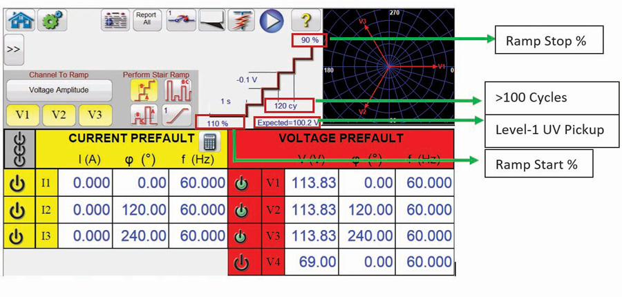
Figure 5: Undervoltage Level-1 Pickup Test Setup
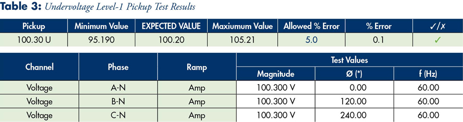
- Timing Test. This timing test can be done using two state sequences. The first state can be set to simulate nominal load conditions with a specified time duration; the second state can be set as a sudden drop in voltage to simulate the undervoltage fault condition. Figure 6A and Figure 6B show the setup. Refer to Table 4 for results. Similarly, overvoltage tests can be performed.
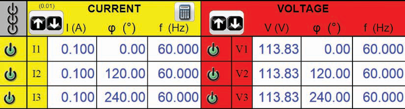
Figure 6A: Undervoltage Level-1 Timing Test Setup: Load Condition State
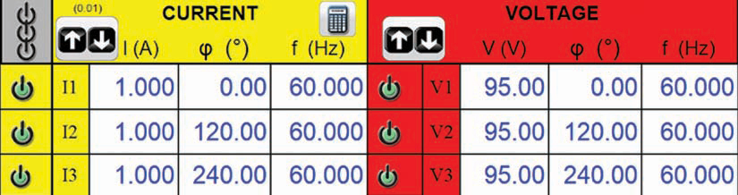
Figure 6B: Undervoltage Level-1 Timing Test Setup: Fault Condition State
- Reclosing Elements
- Unsuccessful reclose test. As the name indicates, this test can be performed to check whether the reclosing logic works as intended and the recloser goes to lockout state if any permanent fault exists. For the reclosing cycle to be initiated, the controller provides the ability to set logic equations as a setting. This setting is a rising-edge detect setting and is supervised by recloser status. It is usually programmed to trigger when the trip condition goes true. Additionally, the controller under test has independent settings for single-pole and three-pole operation mode. Special attention is needed to set the test template to work as per the set operation mode.
The scheme uses a three-phase recloser capable of tripping and closing all three phases in unison. It is designed for just one reclose shot before going to the lock-out state in case of a permanent fault.
Popularly, state sequencer is used to design a test template to validate the auto-reclosing sequence in the MV recloser switch controller. Both controller and recloser on the pole can be simultaneously tested. Any modern test equipment with an interface to connect the control cable can be used. In a situation where only controller testing is desired, there is no need for special equipment with the interface. One can use binary outputs on test equipment to simulate breaker conditions.
Depending on the number of shots, the state-sequencer file can be adjusted for the number of states. Since one shot is programmed in the controller under test, the total number of states needed will be five.- A pre-fault state 1 is needed to simulate load conditions with the breaker closed for the amount of time the controller takes to reset from a past lockout. If the controller is already in the reset state, there is no need to delay.
- State 2 can be programmed to simulate trip conditions that initiate a reclosing sequence. In this state, test equipment expects to receive a trip signal; therefore, the timeout has to be long enough in case there are any timed elements in trip logic. According to the logic diagram of the trip output described in the previous section, a single-phase undervoltage condition can be simulated as a fault.
- State 3 can be simulated similar to state 2 where the fault condition still persists. As part of an agreement with utility operators for reconnection, the controller under test is set to wait four hours before going to lockout if it doesn’t read three-phase healthy voltage.
For testing purposes, the wait can be reduced since it is just a timer. The event report shown in Figure 7 indicates a three-phase lockout (79LO3P) trigger after the timer, which is set to 23 cycles in this particular scenario, expires.
- Successful reclose test. As the name indicates, this test verifies that the reclosing logic works as intended and goes to reset state if any temporary fault exists. Similar to the unsuccessful reclose test, state sequencer can be used. Moreover, this test will ensure whether the set open interval timer for the reclose shot works as expected. State 1 and state 2 can be copied and pasted from the previous test. State 3 can be simulated as a recloser breaker opening condition with a timeout equal to the minimum trip duration timer set in the controller. The timer is usually set around 40 cycles for motor-operated reclosers; it is seen to be around 12 cycles for fast reclosers. This 40-cycle timer effectively adds on to any open interval time for auto-reclosing; therefore, it is better practice to have separate states for reporting purposes. Keeping that in mind, state 4 can be designed for the test equipment waiting to receive a reclose signal with a timeout little more than the set open interval time for shot 1.
- Yellow operating-handle test. Some reclosers are equipped with a yellow operating handle that permits manual opening of the recloser. Pulling the handle down trips and locks open the main contacts and opens the low-voltage closing circuit of the recloser. The status of the handle is provided through the control cable to the controller. The contacts in the trip/close circuits open and stay open when the respective external handles on individual poles are pulled to lock-open positions. In many situations, just one of the opto-isolated wetting inputs of the controller monitors the combined status of the handle for individual recloser poles. The controller drives to three-phase lockout after sensing a time-qualified rising edge on that input.
Binary outputs on any modern test equipment can be used to mimic the handle status when the recloser breaker is not connected to the controller. Simulating a closed contact condition to that wetting voltage input indicates a normal system, whereas an open contact condition provides a handle operation state to the controller. State 1 and state 2 in the test software can be designed in the same fashion as an unsuccessful reclose test with an addition of providing closed binary output status for the yellow handle. State 3 should have open binary output.
- Unsuccessful reclose test. As the name indicates, this test can be performed to check whether the reclosing logic works as intended and the recloser goes to lockout state if any permanent fault exists. For the reclosing cycle to be initiated, the controller provides the ability to set logic equations as a setting. This setting is a rising-edge detect setting and is supervised by recloser status. It is usually programmed to trigger when the trip condition goes true. Additionally, the controller under test has independent settings for single-pole and three-pole operation mode. Special attention is needed to set the test template to work as per the set operation mode.
- Frequency Elements
Both underfrequency and overfrequency elements must be tested for their pickup level and operation time. These elements are independent in the controller and follow a definite time operation concept where the timer starts the moment pickup is reached and stops after the set operation time irrespective of the frequency level. It is crucial to know the unit (cycles or seconds) of the set time before advancing to all the tests.
For pickup tests, frequency ramp is done with a long sequence to control the phase angle at each step of the sequence to create a smooth waveform and not one with jumps. The formula to calculate phase shift to obtain smooth is based on the rotating phasors with different pulsation (frequency).
Vectors A1 and A2 in Figure 8 represent present and future frequency vectors. The algorithm is recursive and is based on calculating the phase angle of the phasor with higher frequency to make sure that when the frequency needs to change, the previous frequency and new frequency vectors are overlapped indicating a continuous transition.
The time from one step to another must be deterministic to calculate the phase angle of the next phasor and know exactly when the frequency changes. For that reason, test software often uses the method that employs state change on zero-crossing.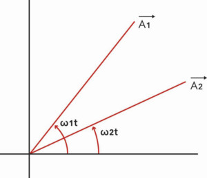
Figure 8a: Frequency Vectors on Time Axis
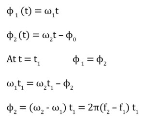
Figure 8b: Frequency Vectors on Time Axis
Another important concept is to understand the relay’s measurement technique. Most relays adjust processing algorithms to track the frequency, and this can make the operate time seem shorter or longer than expected. The response time of the frequency elements to a valid frequency change is around three cycles in the controller under test. The testing crew must be cautious not to miss entering a time interval of more than three cycles between frequency changes in the test software.
The frequency elements of the controller operate on the frequency determined from the A-phase source-side voltage terminal. An undervoltage supervision check is also programmed to ensure frequency elements do not operate for a fault condition, since faults create transients that can result in incorrect system frequency measurement. Frequency elements are blocked until the system voltage recovers above the specified threshold, which is set to 12.5 Volts in the test example. Figure 9 shows the settings considered for this article.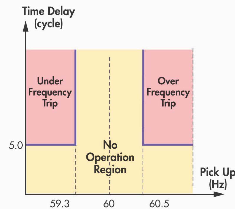
Figure 9: Frequency Element Settings
Frequency elements are pretty tight on tolerances, and entering the right information is crucial. Tri-time tolerance for the controller under test is +/- 0.25 cycle plus +/- 0.1%, and pickup accuracy is +/- 0.01 Hz. Figure 10 shows a test setup screen with all the useful information. Prefault phase-to-neutral voltage of 69 V, higher than a UV block setting of 12.5 V, is entered. Note that the software is programmed to use two binary inputs on the test equipment. Input 1 will trigger when pickup is achieved, whereas input 2 will be triggered after the operation time lapses. A start time of three cycles is typically used to account for frequency tracking purposes explained earlier.
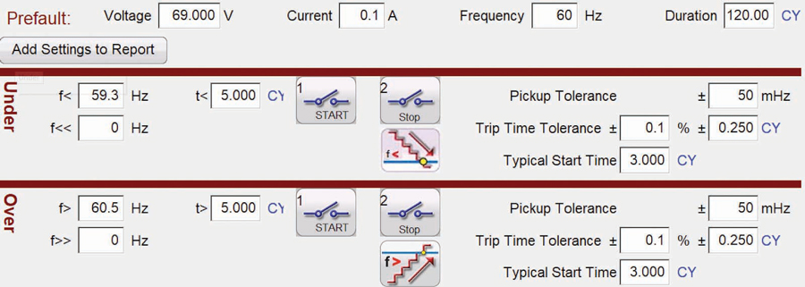
Figure 10: Frequency Elements Test Setup
Figure 11, Figure 12, Figure 13, and Figure 14 show the results of frequency elements. Pickup and timing tests are both necessary.
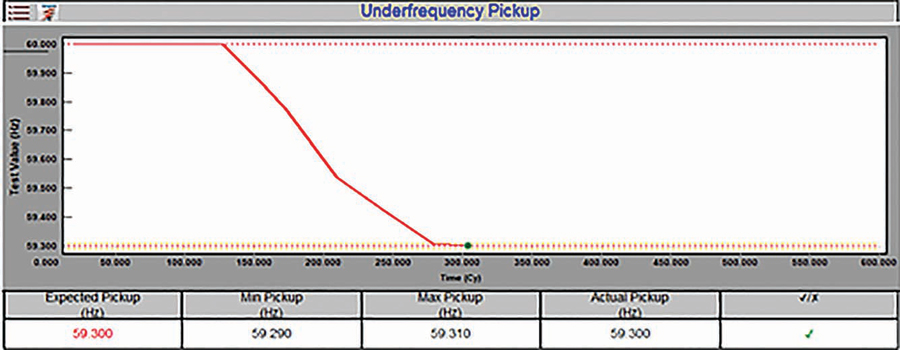
Figure 11: Underfrequency Pickup Test Results
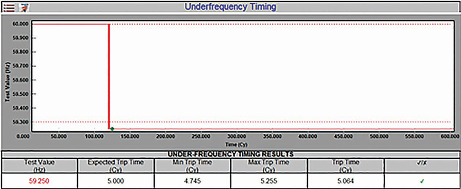
Figure 12: Underfrequency Timing Test Results
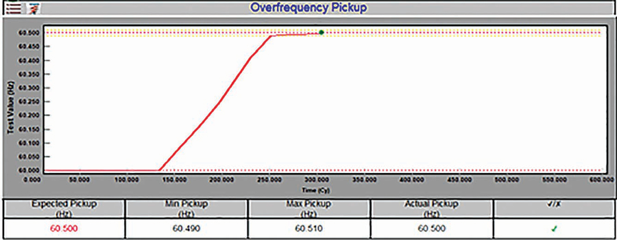
Figure 13: Overfrequency Pickup Test Results
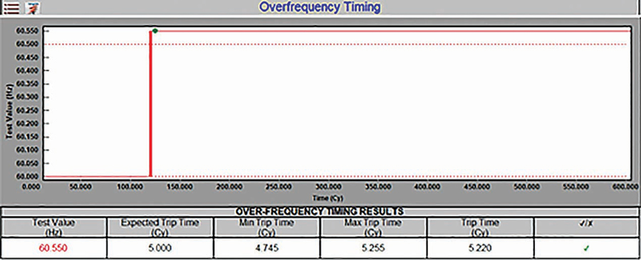
Figure 14: Overfrequency Timing Test Results
Commissioning and Interoperability Tests
This group of tests includes field tests that are useful to check system operation and interoperability — that is, the dynamic response of grid-tie inverters and recloser switch at the point of common coupling (PCC).
Step 1. Verify system components. A field commissioning group must verify the engineering parameters and confirm proper programming for the inverters and recloser control settings. Test results should be documented to comply with ANSI/NETA ATS and coordination study requirements. The local SCADA system should provide the status of each inverter.
Step 2. Verify the complete sequence:
- The utility will intentionally drop a phase.
- Immediately followed by the phase drop, the recloser switch must disconnect, and inverters should not produce any power.
- The utility brings back the missing phase and restores voltage. Immediately, the recloser takes action to verify healthy voltages on the grid side.
- Verification time is usually available as a setting in the recloser relay logic and can be tested easily.
- After this delay, reclose occurs and voltages are restored to the grid and the line side of the inverters.
- Voltage is restored, and the inverters should be timed to verify the start of power production after approximately five minutes.
- The same procedure is repeated dropping each phase.
Step 3. A final recommended step is phase sequence verification. A drop in A-phase voltage on the recloser switch side should result in the same phase drop on the recloser. Similarly, other phases should be tested for a complete phase sequence.
Conclusion
The requirements for grid connection of distributed generation need detailed scrutiny to comply with EPS requirements. This article presents relay protection testing procedures to aid in validating the MV recloser control and operation as part of a PV solar farm system.
Strategic steps in the relay testing routines included validation of the real operation for the MV recloser at the PCC, including detailed practical scenarios where the relay protection system must respond properly for continuity of service (i.e. reconnection and coordinated verifications) as well as protection of equipment assets (i.e. coordinated disconnection and lock-out.)
Even though it is not possible to subject the MV recloser protection system to all possible scenarios in a constantly changing grid, it is important to have a testing methodology to validate protection system settings and coordinated response with other parts of the solar farms, i.e. inverters.
 Mohit Sharma is currently part of the engineering team at Megger where he designs, develops, and validates testing solutions in the areas of system protection and automation. In 2015, he joined Megger as an Applications Engineer for protective relay products after receiving his MS in electrical power systems engineering from North Carolina State University, Raleigh. Mohit obtained his BTech in electrical engineering from the National Institute of Technology, Bhopal, India, and worked with India-bulls Power as an Electrical Maintenance Engineer responsible for the testing and maintenance of LV and MV switchgear. He is currently a member of IEEE-PSRC.
 Luis Montoya, PE, has worked in the industry in several positions in the electrical industry as an Engineering Manager in low- and medium-voltage electrical testing and design. He is currently a Senior Systems Engineer for FlexGen Power Systems and a PhD candidate in electrical engineering at North Carolina State University with a concentration in power system and power electronics, including active power harmonic filters. Luis was a senior engineer in designing and testing solutions for utility-scale project substations and solar farms. He most recently led efforts in arc flash analysis, protection coordination, MV and LV field testing, and power quality field testing and solutions. Luis graduated from the National University of Colombia with a BS in electrical engineering with a concentration in power systems and received his MSEE from the University of Wisconsin, Milwaukee with an emphasis in power electronics and renewable energy.