

During the life cycle of a substation automation system (SAS), it takes considerable effort and time to test the communication, interlocking logic, and proper operation of all signals transmitted to supervisory control and data acquisition (SCADA) systems. In a substation that makes use of IEC 61850 communication, all the engineering and configuration data can be saved in standard-format files — the so-called system configuration language (SCL) files. This article presents a new test approach that increases efficiency in testing the automation and control functionality of a SAS. It discusses the intelligent electronic device (IED) data model, SCL file requirements, and network design considerations that should be considered when specifying and designing a system.
THE PROCESS
Testing the protection element settings of IEDs and protection schemes are well-established practices when testing a protection, automation, and control (PAC) system. Tools and methods are available to support standardized and automated testing routines. Test plans can be created for specific relay types and schemes to be reused during distinct phases of a project, such as factory acceptance tests (FATs), commissioning, site acceptance tests (SATs), and maintenance.
On the other hand, testing the SAS, which involves automation, control, and SCADA functionalities, is usually performed manually. When looking at the time spent during commissioning, for example, testing the automation and communication system is currently more time-consuming than testing the protection functions. Automation systems have become increasingly complex, and the efforts to test communication, interlocking logic, and proper operation of all signals transmitted to SCADA systems have grown dramatically.
In substations with conventional hardwired interfaces, all wiring and cabling connections between IEDs must be checked as part of the FAT and SAT. This is performed one by one in a manual process of “green marking” all interfaces on printed functional and wiring diagrams. To test the relay logic, the physical inputs must be forced and the logic verified either by monitoring LEDs, outputs, or with assistance from IED software. To test SCADA signaling, an end-to-end (also referred to as point-to-point) check is performed by stimulating the signals directly at the equipment level in the switchyard or by forcing them at the IEDs. Additional documentation, such as a spreadsheet with remote terminal unit (RTU) signals and mappings list, is typically required.
In a substation with IEC 61850 communication-based interfaces, the process of testing the automation and control can be improved by using software to replace some of the manual steps previously described. This process can be even more efficient if some of the optional features defined by the IEC 61850 standard are used while exploiting the capabilities of the SCL.
IEC 61850 AND THE SCL CONCEPT
IEC 61850, the international standard for power utility communications, defines not only communication protocols, but also data models for substation equipment and abstract communication services. The three classes of communication services defined by the standard to be used for substation protection, automation, and control are client/server, generic object oriented substation events (GOOSE), and sampled values (SV). Moreover, the standard specifies a common, vendor-independent, configuration concept. Machine-readable configuration information in an XML-based standardized format is used in this process — the SCL.
SCL Engineering Process
The SCL concept is defined in IEC 61850-6.
Its main purpose is to allow the exchange of communication system configuration data between different configuration and testing tools in a compatible way. Figure 1 shows the general concept of the engineering process of a substation automation system using SCL data exchange.
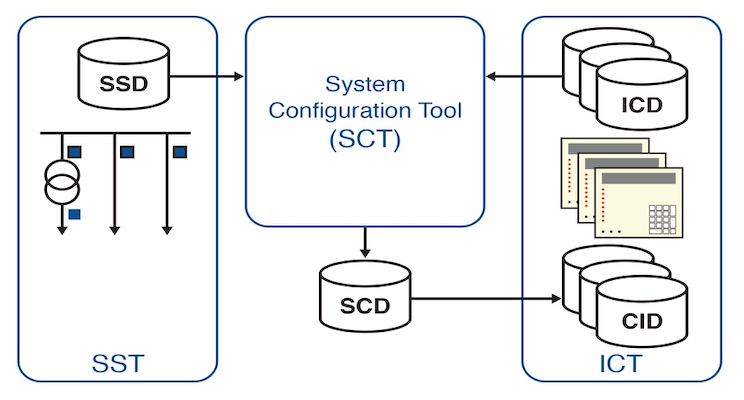
Figure 1: SCL Concept
The following types of SCL files, with different extensions, are specified for information exchange:
• SSD (system specification description) describes the single-line diagram of the substation, existing voltage levels, primary equipment, and required logical nodes for implementing substation functions. The SSD file is generated by a system specification tool (SST).
• ICD (IED capability description) describes the functional capabilities of an IED type. Each IED type has a related ICD file that contains the IED logical nodes, data, and supported services. It is generated by the IED configuration tool (ICT).
• SCD (substation configuration description) contains all configured IEDs, the communication configuration, and all IEC 61850 aspects for a given system. It is created by the system configuration tool (SCT).
• CID (configured IED description) contains a subset of the SCD file with all information related to one specific IED. Private extensions are allowed.
Edition 2 of IEC 61850 defines two other file types: the IID (instantiated IED description) file, which describes a single IED preconfigured for a specific project, and the SED (system exchange description) file that will be used for exchange of data between two different projects.
There are three types of engineering tools in this process: system specification tool (SST), system configuration tool (SCT), and IED configuration tool (ICT).
The SCT allows engineers to design and configure the system-wide IEC 61850 communication dataflow. ICD files from all IEDs and the SSD file are imported into the SCT. The tool should allow the configuration of IEC 61850-related features of the IEDs, configuration of horizontal communication links (GOOSE and sampled values), and configuration of vertical communication links (client/server reports). By using data from the SSD file, the engineer can also associate IED functions (logical nodes) to the single-line equipment and functions. Ultimately, the SCD file, which documents the complete system, is generated by the SCT.
The ICT is a manufacturer-specific tool used to generate ICD files and to load the CID configured files into the IED.
SCL Scope
The SCL language in its full scope describes a model comprised of three basic parts:
1. Substation describes the single-line diagram of a switchyard and the primary equipment and functions that are used. The substation equipment and functions are related to logical nodes contained in the IED.
2. IED describes all the hardware devices (IEDs) used in the substation automation system. The data model implemented in the IED, including its logical devices and logical nodes, is described in this part. IEDs are connected to the communication system via its access points.
3. Communication describes logically possible connections between IEDs in subnetworks by means of access points (communication ports).
The content of a complete SCD file (Figure 2) is comprised of these three parts plus a section with data-type templates describing which data and attributes are used by the IEDs.
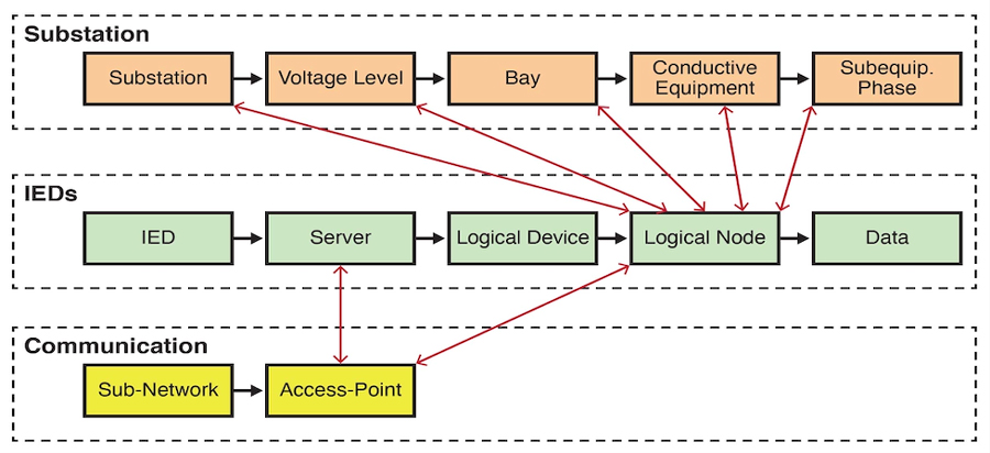
Figure 2: Simplified SCL Content
Substation Structure and Functional Naming
The substation structure represents the primary system architecture; it describes which primary equipment functions are used and how the equipment is connected. The objects in this session are hierarchically structured and designated according to IEC 81346. Figure 3 shows an example of a substation single-line diagram following the naming conventions of IEC 81346 for the substation structure and equipment such as disconnect switches and breakers.
The main purpose of this section is to derive a functional designation for the IED logical nodes from the substation structure. When naming signals, applications can make use of the IED-related naming or the functional-related naming.

Figure 3: Example Substation Topology
Functional naming is a signal identification based on the substation structure names down to the logical node (LN) class, followed by the semantically complete standardized data object and attribute names. The switch position of QB1 in bay Q01 of Figure 3 could then be identified by the path name AA1D1Q01QB1/CSWI.pos.stVal and be associated with a CSWI logical node of an IED located at bay AA1D1Q01, where:
• AA1: substation name
• D1: voltage level name
• Q01: bay name
• QB1: equipment (disconnect switch) name
Content and Usage of SCD Files
As explained above, the SCD file is the ultimate file resulting from a completed IEC 61850 system design. The SCD file is used not only by engineering tools and for documentation purposes, but also by testing tools. Testing tools can support more efficient testing by taking advantage of the SCD file information about the substation under test.
However, while the standard defines a clear concept for the engineering process, it does not define the minimum content requirement for the SCD file. Topology information in the substation section, for example, is optional. Information in the IED section depends on the capabilities of the specific IED products used in the project. It is clear that the degree of efficiency testing tools can provide depends on the capabilities of selected IEDs and on the overall information made available in the SCD file.
CONSIDERATIONS WHEN ENGINEERING IEC 61850 SYSTEMS
Testing requirements should be an integral part of the engineering process. To increase test efficiency, how the SAS system will be tested throughout its lifecycle should be clearly defined during the specification and early design phases.
IED Requirements
The previous section alluded to the fact that the information contained in the SCD file is of extreme importance to what the testing tools can deliver. Therefore, it is important to understand some of the IED and SCD key requirements for optimal testing. This section discusses some of these requirements, what to consider, and shows how to engineer the system.
Test mode and simulation flag
When testing already energized substations or during maintenance activities, precaution should be taken to isolate IEDs under test. This will avoid any accidental breaker trip or undesired exchange of signaling between IEDs due to the test. Edition 2 of IEC 61850 provides two enhanced features that should be available to accomplish the test isolation.
• One feature is the option to put a function or IED in test mode using the data object mode (Mod). Based on the Mod value of individual logical nodes within a logical device, the resulting test-mode status is determined by the attribute behavior (Beh). IED manufacturers usually opt for a simple implementation with one Mod data object used to set the entire IED in test mode. The possible values for the Mod data objects are on, blocked, test, test/blocked, and off.
• The other feature is the simulation flag in GOOSE and sampled values. Subscribers should support handling of the simulation flag. The data object LPHD.Sim serves as a switch between the messages coming from the real IEDs in the system and simulated messages coming from test sets or testing tools.
LGOS and LSVS
Verifying a GOOSE or sampled values message that is being published is not a complicated task. As these messages use a multicast mechanism, they can be easily sniffed in the network. However, verifying the subscription of these messages by other IEDs would not be an easy task without the introduction of supervision logical nodes to the data model of IEDs.
IEC 6185074, Edition 2 defines the LGOS (logical node for GOOSE subscription) to be used for monitoring the status of GOOSE subscriptions. Similarly, the LSVS (logical node for sampled values subscription) is used to monitor the status of SV subscriptions.
Instances of LGOS and LSVS logical nodes should be available for each configured subscription to allow testing tools to automatically verify, via a client/server connection, the reception of messages. The testing tool can identify a problem when the GOOSE/SV is not received or when there is a configuration mismatch between publisher and subscriber.
Report owners and static datasets
Report is a client/server service defined by the standard and used in SCADA systems to transmit an event list from a server (IED) to a client (RTU, gateway, or human machine interface (HMI)). It uses the multimedia messaging service (MMS) protocol and establishes a one-to-one connection between clients and servers.
Report control blocks in the IED data model contain configuration parameters about the reports. The standard defines an optional attribute “owner” that can be used to identify which client is using the report. By polling the report control block’s owner attribute value, a testing tool can check whether preconfigured client/server connections are active.
Datasets are used by reports to determine which attributes (signals) of the data model will be included in the report. Datasets can be created statically or dynamically. A dynamic dataset is created by the client after establishing connection to the server (i.e. the client) defines the content of the report. The content of the dynamic data set is not described in the SCD file and is typically documented in a separate and often inconsistent SCADA signal table. On the other hand, a static dataset is defined in the system configuration tool while configuring the IED and cannot be changed by a client. The use of static datasets has the advantage that the data in the report is described in the SCD file and available for documentation and testing purposes. In any case, the dataset should include only those data objects (signals) that are in fact processed by the respective client. Overloading the data set with all the signals available in the IED’s data model will just create unnecessary network loads, make the signal tests more difficult, and produce very large SCD files.
SCD File Requirements
This section discusses some requirements for the content of SCD. For illustration purposes, an example of extracts from SCD files are shown to demonstrate how the information should be included and the subsequent benefit for testing tools. It is important to mention that users configuring the system should not manually edit these SCD files. The system configuration tool should offer an easy graphical interface for creating and configuring the SCD file.
Substation topology and association between switchgear and LNs
As mentioned in the previous section, the substation portion of the SCD file is optional. If the engineering tools support the configuration and this section is structured properly, testing tools can display the IEDs and equipment in the right location in a structured way.
Figure 4 shows part of the SCL substation section for the example substation in Figure 3. The hierarchical structure <Substation>, <VoltageLevel>, <Bay>, and <Equipment> is present and configured.
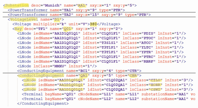
Figure 4: Example of SCL Substation Section
Figure 5 shows an example of a testing tool after importing the SCD file of the substation in Figure 3. The five bays (only three represented in the figure) of the 380kV switchgear are grouped accordingly, with the respective breakers and disconnect switches allocated to each bay. The IEDs are also allocated in the respective bays. Even though the single-line diagram information is not fully present in this case, the information is enough for the testing tool to display the equipment and IEDs in a meaningful and understandable way.
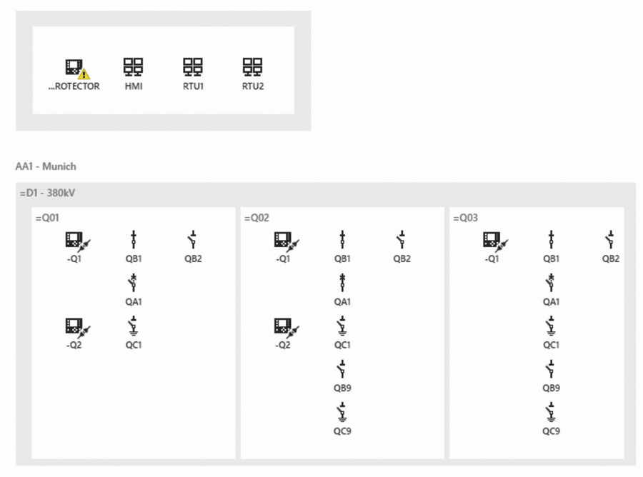
Figure 5: Example Substation Displayed in Testing Tool
Switchgear equipment (e.g. breakers and disconnect switches) should be associated to IED logical nodes. The engineering tool should allow a graphical configuration of this association and define them in the SCL substation section using the <LNode> references. Figure 4 showed the SCL example of the breaker QA1 at bay Q01, which is associated with the logical nodes XCBR, XSWI, and CSWI of the IED named AA1D1Q01Q1.
Figure 6 shows these signals associated with the QA1 breaker when selecting it from the diagram of the testing tool. As they are associated with logical nodes from IED Q1, the tool can indicate whether these signals are being transmitted by the IED via GOOSE or reports. In Figure 6, GOOSE signals are represented by purple lines, and reports are represented by the teal lines.
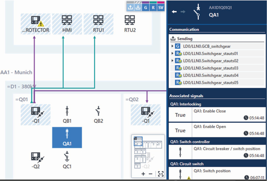
Figure 6: Signals Associated with the QA1 Breaker
Similar to the breaker, CTs and VTs can also have <LNode> references to TCTR and TVTR LNs of IEDs.
SCL description attributes
If data objects are equipped with SCL “desc” description attributes, then the testing tool can display this text as the signal name. Engineering tools often allow the user to enter custom names for data objects. Instead of visualizing IEC 61850 logical node, data object, and attribute names, the user can view signals according to those naming conventions. IEC 61850 complexity can be hidden and displayed only by request. Figure 7 shows a clear description of the breaker position in the main window, while the XCBR logical node naming is only shown in the detail view.
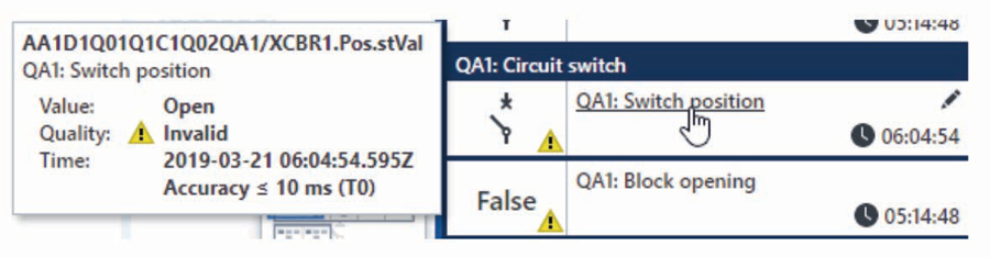
Figure 7: Display of Signal Description
GOOSE configuration
The LGOS logical node described within the IED requirements section defines which GOOSEs are being subscribed and allows monitoring the subscription status. The SCL language offers other ways of describing subscriptions. They can be described within the IED section of the SCL file by using the <IEDName> element under the GOOSE control block (<GSEControl>) or using <Inputs><ExtRef type=”GOOSE”> elements. Figure 8 shows the GOOSE configuration of IED AA1D1Q01Q1 in the SCD file of our example substation and shows that five other IEDs are subscribing to it.
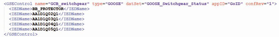
Figure 8: GOOSE Subscriptions Defined in the SCD
Testing tools are then able to represent the GOOSE links and relation between publisher and subscribers, as represented in Figure 9.

Figure 9: Representation of GOOSE Connections
Additional valuable information about the GOOSE configuration, which should be included in the SCD file, are the minTime and maxTime attributes. These attributes are optional and describe the minimum and maximum retransmission times used by the IED publishing the GOOSE.
Report configuration
Like the GOOSE described above, report connections for the SCADA system can also be described in the SCD file. HMIs, RTUs, or gateways can have report control blocks reserved for them. This should be declared using <ClientLN> in the <ReportControl> element as illustrated in Figure 10 and Figure 11.
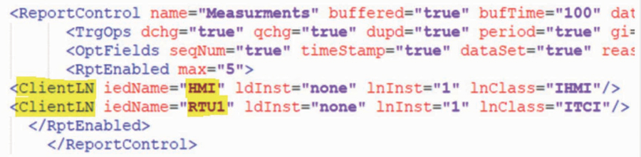
Figure 10: Report Control Block with Clients Reserved
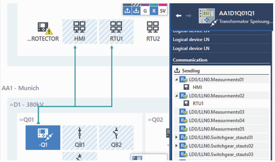
Figure 11: Testing Tool Displaying Report Connections
Network Design
When designing the communication network, engineers should take testing aspects into account. While testing during a FAT may offer flexibility in terms of plugging and unplugging devices from the network, there should be strong limitations as soon as the substation is energized. A clear test procedure and test cases for different scenarios should be specified during the SAS specification phase. The network should enable testing without exposing the system to any possible malfunction or cybersecurity issues.
Network topology
When designing the topology of the network, physical access points should be clearly defined for testing purposes and represented in the SAS documentation. The physical location of the access points must also be considered. Test personnel should be well-informed about where to connect test sets and test laptops for a specific testing event. For monitoring the communication system, access to all network segments, process bus, and station bus should be available giving visibility of the entire system. In case of HSR (high-availability seamless redundancy) and PRP (parallel redundancy protocol) redundant networks, the use of RedBox (redundant box) should be considered for connection of test sets.
Traffic control
To prevent or minimize overloads, unnecessary traffic can be limited in the network. Multicast or virtual local area network (VLAN) filtering are two mechanisms that can be used to control traffic in a network. VLAN, for instance, allows logical separation of a network. During the engineering design, each GOOSE and sampled value can be assigned to VLAN domains, while each port in the switches is configured to the VLAN it belongs to. The ability to test the SAS system should be considered when designing traffic controls to avoid the need for any posterior configuration changes only for testing purposes. One example, in the case of VLAN filtering, is to predefine which ports will be used for connecting test sets and configure the VLAN domains of these ports accordingly.
TESTING THE SUBSTATION AUTOMATION SYSTEM
As mentioned previously, testing the automation and control functionality are usually performed in a manual way. Tools offering testing capabilities on a per-IED basis, allowing test and simulation of IEDs individually, are available.
Test Approach
The method presented here extends the test from single IED testing and simulation to testing the entire substation automation system. The test is entirely based on the SCD configuration file of the system. By importing the SCD file, the entire system can be visualized, and all information available in the SCD is used. The information in the substation section is used to place IEDs and switchgear equipment within their voltage levels and bays. As was seen in Figure 5, the tester can view the system in a very similar way as the single-line diagram or the local substation HMI, which testers are already familiar with.
The method proposed is suitable for testing the SAS during its entire project lifecycle. The project phases are described at IEC 61850-4 and illustrated in Figure 12. The tool using this method should support monitoring as well as simulation of the system. When testing the system, the test set should have access to the network traffic and an MMS connection to the IEDs.
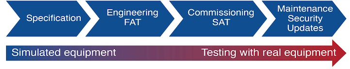
Figure 12: SAS Project Lifecycle
During specification, the SCD file can be validated and used to support the configuration of devices. Development and testing of SCADA RTUs and HMIs can start by simulating the communication behavior of all IEDs in the system. During the FAT, IEDs that are not yet present can be simulated to test the ones already installed and available. As the project moves into the commissioning stage, more monitoring and testing of the real IEDs is done instead of simulation.
One of the key factors for an efficient approach is the option to create test plans. A test procedure can be documented and reused throughout the SAS lifecycle (Figure 13). Test sequences can be performed and assessed automatically.
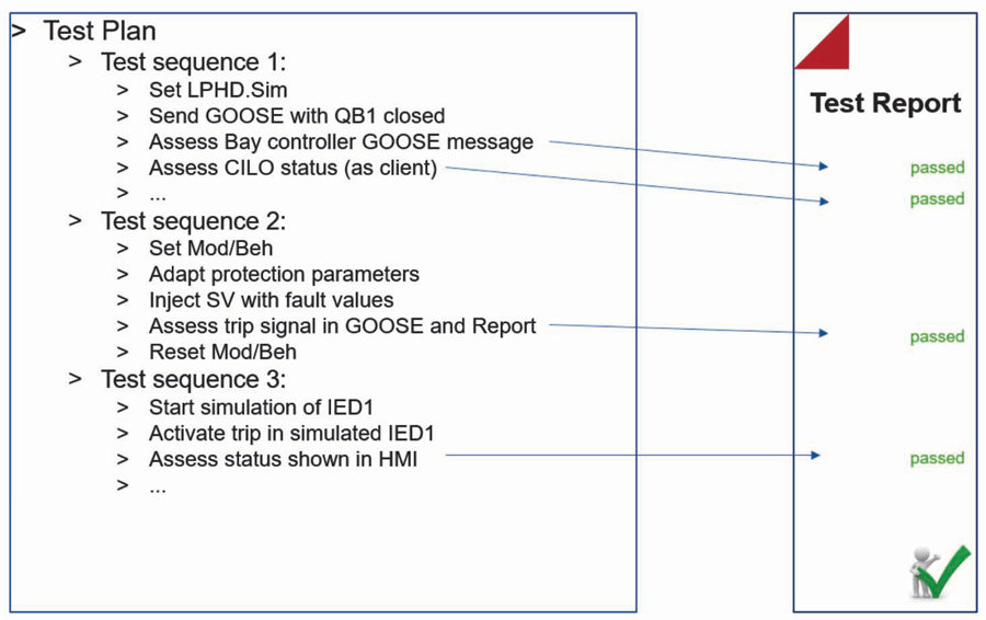
Figure 13: Test Plan Example
Several test cases related to the SAS system are discussed in the following sections of the paper.
Verifying Communication Links
By loading the SCD file and having access to the network traffic and MMS connection to the IEDs, the testing tool can automatically validate all GOOSE, sampled values, and report communication links.
The test set can poll for attributes in the IEDs and validate against the model. It can check, for example, whether the report control blocks are enabled and if the owners of the reports are the clients declared in the SCD file.
GOOSE communication links can be verified for:
• GOOSE mismatch on the sender side by verifying control block settings
• GOOSE publishing errors by sniffing on the network and comparing against SCD
• GOOSE subscription errors by verifying the LGOS statuses at each subscribing IED; mismatches are also checked.
Figure 14 illustrates an example where the GOOSE published by an IED is verified in the network but a problem is identified at one of the subscribers due to a mismatch in the configuration revision. The connection link is highlighted in yellow, and warning signs are displayed to indicate the issue.
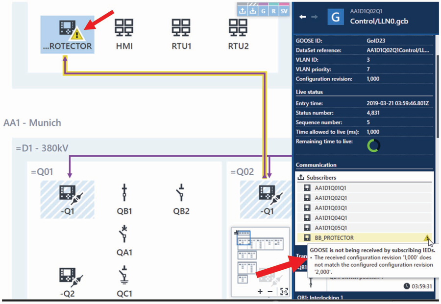
Figure 14: Check of GOOSE Publisher-Subscriber Links
Testing Interlocking Logics
Logic is implemented in IEDs to cover many automation functions. They can automatically be tested using this approach by simulating the inputs of the logic (either via IED simulation or real switchgear status) and the result of the logic can be assessed. One application example is the use of logic for interlocking schemes to ensure proper operation sequence of disconnect and grounding switches (Figure 15). To represent the result of interlocking logic conditions, IEC 61850 represents the status of the release in the logical node CILO. For testing, all combinations of inputs can be tested, and the logic output can be assessed by reading the CILO status values automatically.
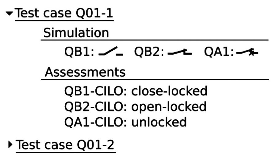
Figure 15: Testing Interlocking Schemes
Troubleshooting by Tracing Signals
There are multiple transfers of messages and signals within a SAS system. A signal passes multiple steps until it arrives at the control center. If there is an error in this communication, the commissioning engineer must follow the signal on its way through the SAS. Finding such signal errors in the case of conventional hardwired substations is very time-consuming. Using the test method indicated in this article within an IEC 61850 substation, it is possible to follow how the signals propagate through the SAS (Figure 16).
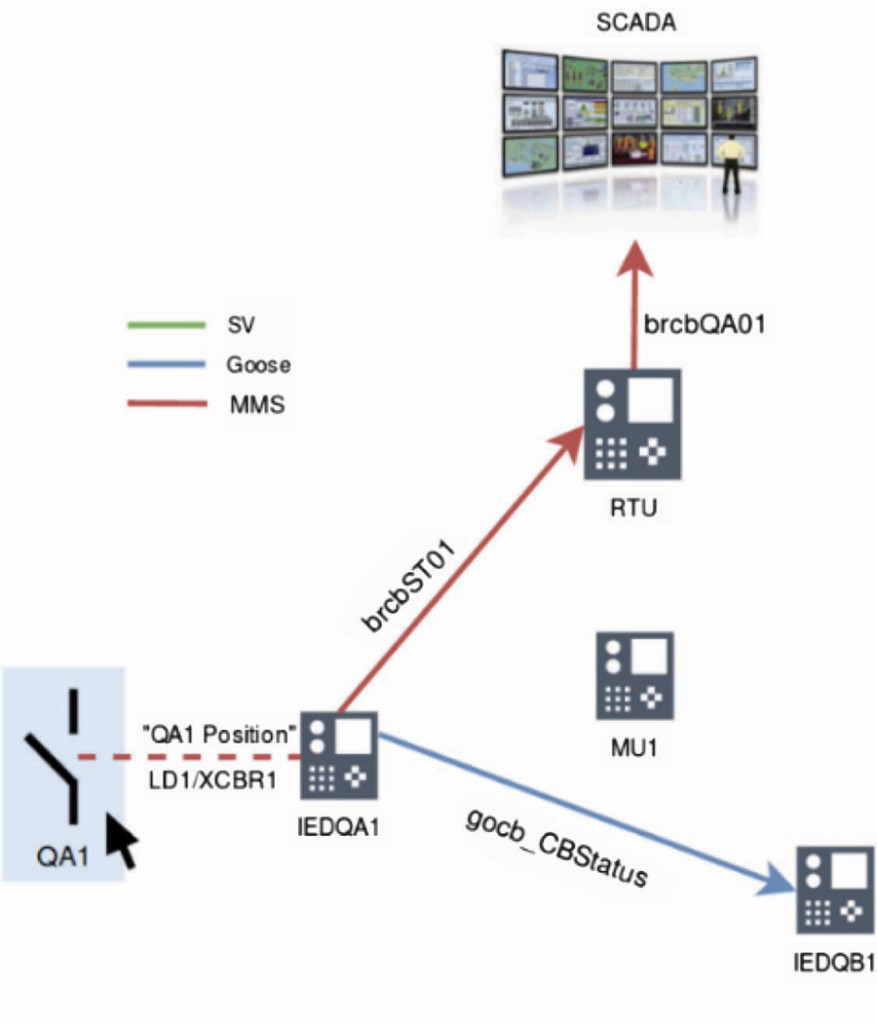
Figure 16: Breaker Position Transmitted over the SAS
Testing RTU /Gateway and Local HMI Configuration
Gateways, RTUs, and local HMIs usually communicate with almost all IEDs in the system, mainly via reports, but also GOOSE. Typically, several thousand signals need to be tested. During commissioning, at least, the most critical signals are tested point-to-point by stimulating the signal in the switchyard. All other signals can be simulated by a testing tool. A test plan can be built with the testing tool simulating all IEDs and signals of the substation for a quicker verification.
Gateways/RTUs, HMIs, and other IEDs in general are often exposed to firmware updates and security patches during their lifetime. The devices can be easily retested (sanity check) after the update by executing the test plan already prepared for that device before it is put back into operation. Those tests can be performed in the substation with all other IEDs simulated by a modern test tool without affecting the devices in operation.
CONCLUSION
The SCL described in IEC 61850–6 represents one of the biggest advantages of the standard because it makes possible the interoperability between engineering tools. All aspects of the communication system can be saved in a SCD file that represents the ultimate documentation of the system. This is particularly important as more and more of the hardwiring of signals between bays is replaced by the extensive use of GOOSE services. In that way, the SCD file becomes as relevant as the as-built drawings and wiring diagrams were before.
However, the lack of tools that exploit the full capabilities of the SCL language was one of the challenges faced by early adopters. This situation is changing with improved tools. Some key features defined in Edition 2 of the standard are also finally being implemented in the IEDs.
Commissioning and maintenance engineers using modern testing tools can also benefit from all the information available in the SCD files. To maximize the capabilities of the tools, key IED and SCL requirements should be met and consequentially requested in technical specifications for tenders and purchasing contracts. These requirements are discussed in this article to support engineers on how the SAS system should be specified and designed.
An innovative test approach was presented for testing the communication, automation, control, and SCADA part of the SAS system, which is based on the SCD file information. Test plans can now be created to document and automate test procedures that have been very time-consuming until now. Automated test plans also enable a quick retest after security patches and firmware updates, which are performed quite often nowadays. Testing is becoming an integral part of the system and quickly evolving into a supervision and monitoring role.
REFERENCES
IEC 61850–4 Ed.2: 2011, Communication networks and systems for power utility automation – Part 4: System and project management.
IEC 61850–6 Ed. 2: 2009. Communication networks and systems for power utility automation – Part 6: Configuration description language for communication in electrical substations related to IEDs.
IEC 61850–7-4 Edition 2, 2010. Communication networks and systems for power utility automation – Part 7-4: Basic communication structure – Compatible logical node classes and data object classes.
IEC TR 61850–90-4: 2013. Communication networks and systems for power utility automation – Part 90-4: Network Engineering Guidelines.
C. Brunner, F. Steinhauser. “Testing and IEC 61850 Edition 2 — What Does it Mean for the Protection Engineer,” International Protection Testing Symposium, 2010.
E. Carvalheira, J. Coronel. “A Testing Approach for Commissioning the Entire Protection System in Sampled Values-Based Substations, SIPSEP – Simposio sobre Protecciones de Sistemas Electricos, Mexico, 2013.
A. Klien, T. Schossig. “New Methods for Testing Automation and Control,” PACWorld Americas Conference, Raleigh, NC, 2018.
 Eugenio Carvalheira has over 17 years of experience in designing and commissioning power systems protection, automation, and control systems. He joined OMICRON in 2008 as an Application Engineer and is currently Engineering Manager for North America based in Houston, Texas. He is an active member of IEEE-PES-PSRC. Eugenio earned a BS in electrical engineering in Brazil and an MS in computational engineering in Germany.
 Andreas Klien joined OMICRON in 2005 and has worked with IEC 61850 since then. He has been responsible for OMICRON’s Power Utility Communi-cation business since 2016. His fields of experience are substation communication, SCADA, and power systems cybersecurity. As a member of Working Group 10 in TC57 of the IEC, he participates in the development of the IEC 61850 standard series. He received his MS in computer engineering at the Vienna University of Technology.