

As large commercial and industrial construction ramped up in the 1990s and the size of facilities grew, electrical distribution transitioned from low voltage (480 volts and below) to medium voltage (12–15 kV). These design changes brought about the need for more sophisticated electrical distribution protection, which coincided with the early generations of electronic protective relays, including the widely employed GE Multilin and ABB circuit shield relays.
As with all electrical equipment, protective relays have a finite life expectancy. Most relays installed in the 1990s and early 2000s have reached their end-of-life with manufacturers announcing they will no longer offer product support. This status means the production of the relays stops, software updates cease, and replacement parts are unavailable.
When this situation arises, facility owners have an opportunity to choose from a wide variety of replacement alternatives. Determining which relay is best requires the owner to reevaluate their functionality needs. Newer relays provide enhanced functions that can improve electrical protection while maintaining coordination selectivity.
The new relay selection process can be daunting as the market is flooded with devices that offer a wide range of features. Because of the level of complexity, many owners hire third-party consultants to assist with selection, testing, and installation. To make the correct choice, owners must consider several questions.
ARE YOUR RELAYS OBSOLETE?
Equipment manufacturers send out notices in advance of planned obsolescence. Many factors can prevent this information from reaching the current owner, such as facilities changing hands, personnel changing positions or retiring, and relays installed in equipment provided by others, including original equipment manufacturers (OEMs).
HAVE YOU CONSIDERED YOUR REPLACEMENT OPTIONS?
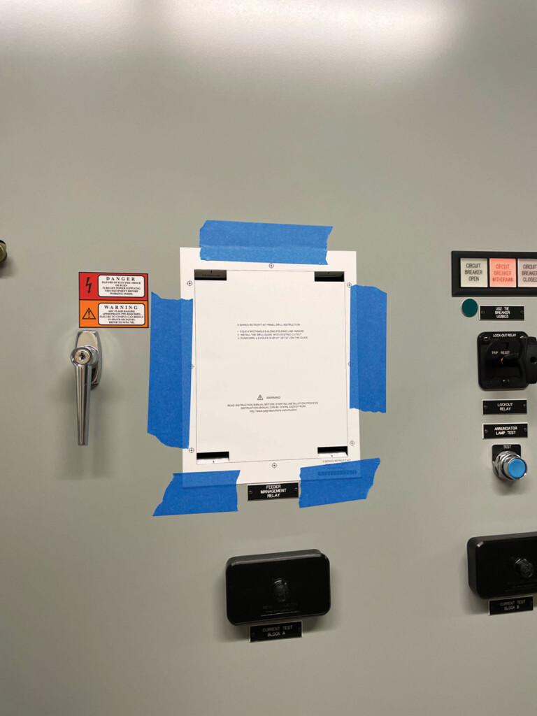
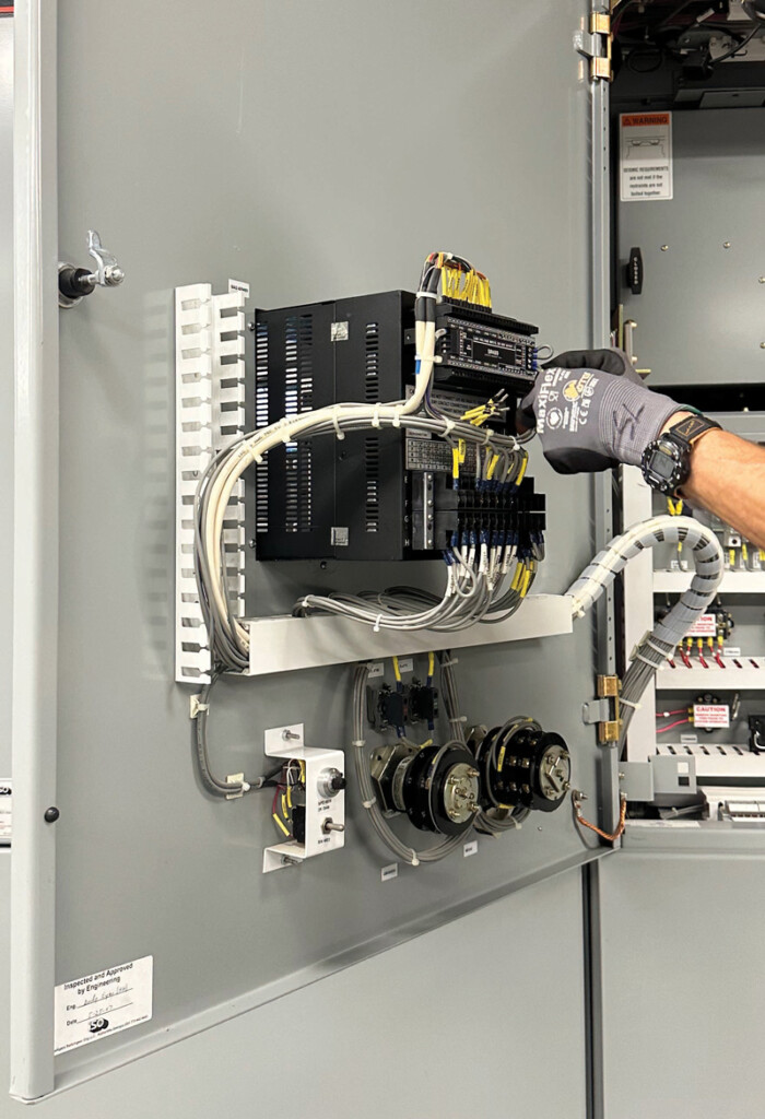
Relay manufacturers offer conversion kits that seem to make the replacement decision easy (Figure 1). However, there are many options and questions to consider. This is an opportunity to revisit the functionality of your relays and decide precisely how you want them to perform. Earlier-generation relays were limited in their options; today’s relays offer more features and capabilities. Were your original relays selected based on need or to make the engineer’s selections easier?
Often, the same relay was specified for all applications, meaning some features were not needed or used. Working with a knowledgeable consultant or testing firm, you can determine your current and future needs to take advantage of new features. You may decide to switch manufacturers based on needs, availability, functionality, or cost. Are you considering future plans for your facility and ensuring the replacement relays will match or complement the new equipment and upgraded monitoring systems you might install?
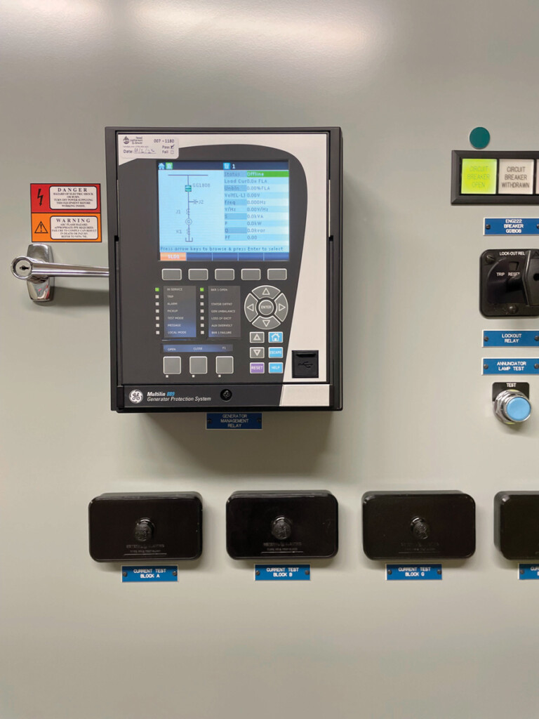
New relays are smarter than their predecessors and come with increased interaction, such as screens that allow you to view their settings and metering telemetry in real time. These screens can also be customized to allow the user to display what is important to them (Figure 2). Many of these relays accept logic statements for complex controls and typical electrical protection. In some cases, this flex-logic capability enables the operator to remove programmable logic controllers (PLCs) from the design altogether and shift this functionality to the relays, thereby simplifying the design.
Another benefit of new relays is their ability to meet the new NEC 240.87 code requirement for arc energy reduction with a local status indicator. The relay can be programmed with energy-reducing maintenance settings (ERMS) to lower the risk of personnel injury when interacting with electrical equipment. The reduced incident energy allows less restrictive PPE, making work easier and safer to perform.
WHAT MIGHT BE WRONG OR MISSING?
Older relays were often used strictly for overcurrent tripping, meaning only current transformers (CTs) were installed. As additional possibilities exist with new relays, potential transformers (PTs) must be added to monitor voltage. Network access is needed when functions such as SCADA, electrical power management system (EPMS), GOOSE messaging (IEC 61850), and other intelligence/logic functions become available. As part of the retrofit process, the testing firm must investigate existing CTs, PTs, wiring, and functionality — or lack thereof.
If the relays aren’t causing equipment to trip, owners assume the relays are working correctly, which is a false assumption. They assume there has never been a fault, and everything is working fine. However, we often find copious issues and vulnerabilities that most sites are unaware of.
Case Studies of Existing Relay Installations
These examples illustrate that relay-related problems are common and often undetected.
- Before replacement, we investigated a site with a relay that was supposed to monitor a breaker’s status. The existing wiring and contacts were incorrect, meaning the relay could not determine the breaker status. We corrected the wiring and confirmed all required functionality as part of the relay replacement.
- We reviewed 20 sites for one client. Only two had documentation of the existing power system coordination study and relay settings that matched the study. The rest of the facilities had random or default settings and no electrical testing stickers, maintenance records, or one-line diagrams. These conditions create a huge challenge when trying to replace/upgrade obsolete relays.
- At a data center, we performed a due diligence inspection and testing of the existing installation before the planned replacement. We found numerous relays with no visual indication that they were inoperative. The relay-enabled LED was illuminated, signifying the relay was in service, but upon software trip simulation, the relay was found to be unresponsive. The facility was unaware of its compromised condition and that this relay provided no protection. Had there been a fault, the upstream device would have operated, unnecessarily de-energizing a much larger section of the facility. This relay has now been replaced, programmed, and tested, restoring the protection that should have been in place.
- One manufacturing plant assumed we could install direct replacement relays in a simple retrofit project. As we inspected the existing relays and wiring, we found that the overcurrent settings in the relays didn’t match the coordination study. Furthermore, the relay outputs didn’t line up with the intended logic and wiring. No one on site had any explanation or knowledge of when and how this condition occurred. This simple project expanded into a new coordination study with new settings and retrofitted relays that were properly programmed and tested.
- An industrial plant was planning to replace the three existing single-phase relays on a medium-voltage (MV) main breaker with a single three-phase relay. While reviewing the existing installation, we performed point-to-point wiring checks and found control power for the breaker trip circuit de-energized. The lack of trip-circuit voltage left the relays unable to open the breaker during a fault condition. The facility was unaware of this issue and how long it had existed. This unfortunate condition would have remained undiscovered except for the relay replacement project.
HAVE YOU PLANNED PROPERLY FOR THE REPLACEMENT INSTALLATION?
Once you have determined which relays to purchase, you must take several more steps to ensure a successful replacement.
- Will you be able to reuse the existing wiring arrangement, or will this need to be revised? The consultant must review the physical space requirements and door configuration to determine whether the switchgear sheet metal must be modified to accept the new relay.
- The consultant or testing firm will need to study the existing wiring diagrams and review how the relays were intended to function. Was the original relay programmed correctly? Does a new relay program need to be written to take advantage of new features or needs?
- Manufacturers have conversion software, but, like most upgrades, it rarely converts all features accurately. In our experience, a detailed review of the relay settings and bench testing is necessary to ensure the programming is done properly. If you choose to change relay manufacturers, conversion software likely does not exist, and a new program must be written.
- New relays always require AC or DC voltage for control power. If this is not already available in the existing switchgear, plans must be made to run wiring from a generator or batteries. We recommend this control power be supplied from a battery-backed source, so the relay stays on if an outage occurs allowing relay protection to remain active and ensuring event recording is functional.
- When replacing generator relays, additional questions come into play. Is this relay the primary protection or the secondary protection for the generator? A generator has its own local monitoring and control/protection settings that may not coordinate with the relay settings. These settings must be determined to achieve coordination with the relay settings. Owners often want the relay to be the first line of defense and the generator monitoring and control device to be the backup.
At a minimum, the following data should be evaluated, if available, and updated as part of your relay replacement project:
- Three-line diagram
- Short circuit and coordination study
i. Utility or upstream protection settings
ii. Downstream devices and settings - Arc flash hazard study
- Available fault current
- Existing wiring, CTs, PTs
- Existing relay setting files
- Physical installation of the new relays
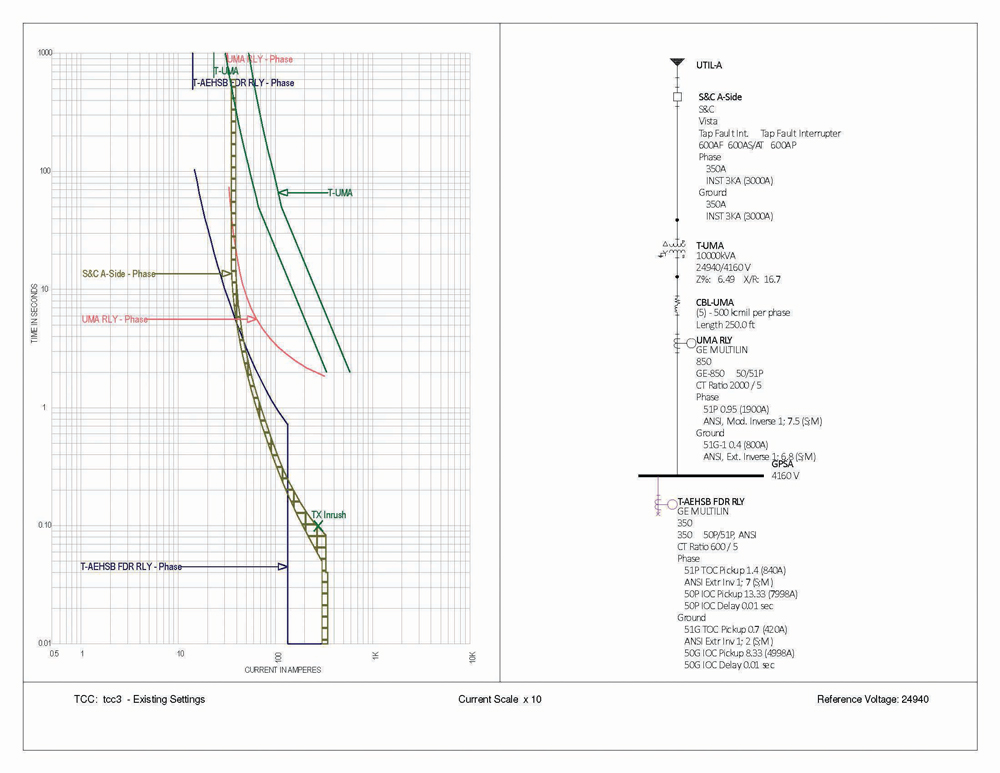
When replacing relays, we frequently discover mis-coordination with the existing system. Figure 3 shows an overlap between multiple relays (S&C to UMA and UMA to FDR) in the system that could result in the wrong device tripping to protect the circuit.
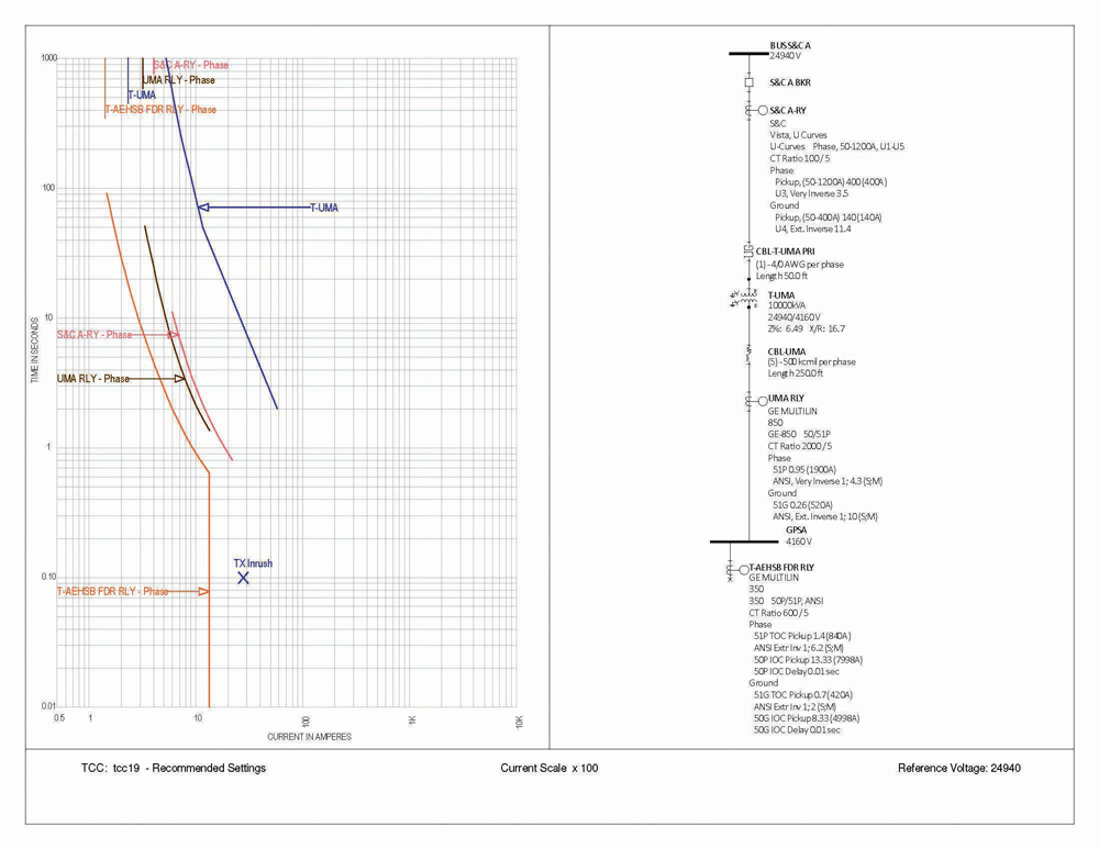
Replacing relays is the opportune moment to re-evaluate the coordination of devices, catch errors, and address changes in the system (Figure 4).
If a facility, such as a data center, has a strong track record with distribution system design, testing, commissioning, and maintenance along with an updated power system study and one-line diagram, relay replacement can go very smoothly. Unfortunately, most sites do not practice this level of investment, maintenance, and accountability. Therefore, their relay replacements are challenging and problematic.
WHO SHOULD BE INVOLVED?
Owners have two options when planning relay replacements: Hire the relay manufacturer’s team to turnkey the project or work with a third-party testing firm and/or consultant. This decision is often driven by cost, availability, and lead time. Whether it’s the relay manufacturer or a third-party firm, the relay programmer should be on-site during the changeout to troubleshoot potential issues (Figure 5).
If an OEM provides the switchgear, they are often responsible for coordinating relay replacement. In this case, their primary interest is getting the replacement accomplished as quickly and inexpensively as possible. We are working with one OEM to provide the appropriate settings for the replacement relays. On most projects, we discover a multitude of missing information and design issues that must be addressed. The OEM passes this cost information along to the owner, usually with little explanation or context, and the owner frequently rejects the additional scope and cost due to a lack of understanding of the potential consequences. In these cases, when matching setting for setting without a thorough review, we must make the disclaimer that we aren’t responsible for incorrect settings or trips as we don’t have enough information or scope to execute the retrofit project properly.
In addition, if a replacement relay is on a main service entrance device with generators parallel to the utility source, the local utility may be involved. There are usually specific utility protection requirements, and they may require witnessing the testing and proper operation of the reverse power function by primary injection testing before the relay is placed into service. The utility, the owner, and the third-party firm must agree on the appropriate settings.
LIVE SITE CONCERNS
Relay retrofits should not be done on energized circuits because the facility is without protection during the upgrade. Typically, the switchgear lineup, or at least a section or cubical, can be de-energized for the retrofit. Some facilities will have an advantage as their distribution system design allows for de-energization and isolation of switchgear (i.e., main-tie-main switchgear). Other sites will be at a disadvantage and will likely have to schedule an outage during the replacement process.
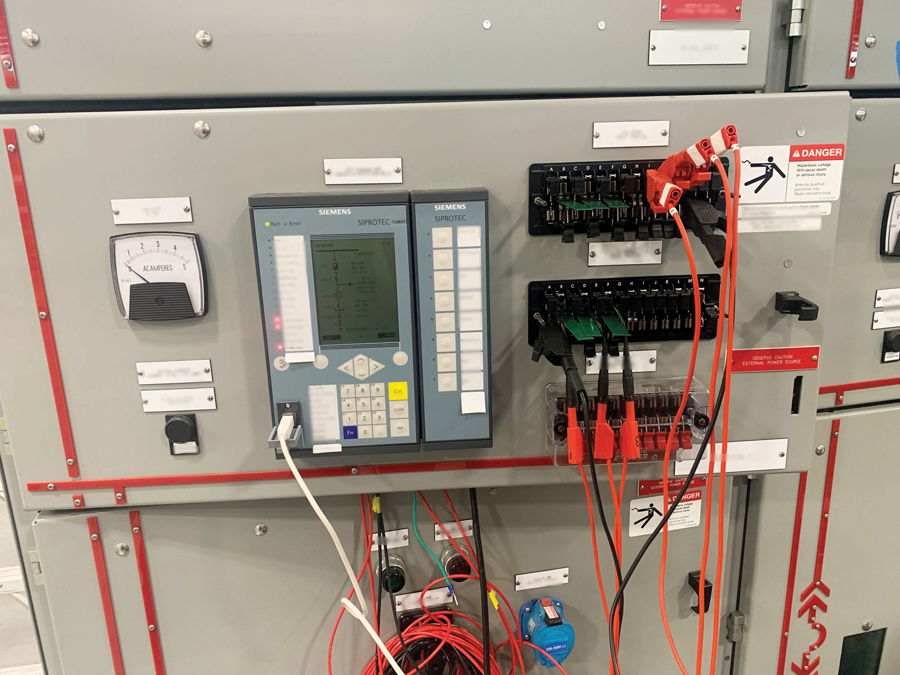
We strongly recommend doing as much bench testing as possible before energization, as primary injection testing is not feasible on a live site (Figure 6). Other nuances throughout this process are often neglected, such as the relays’ interactions with a site’s building management system (BMS) and EPMS. These systems must be checked and reprogrammed to maintain relay communication and functionality.
KEYS TO SUCCESS
Many owners are underprepared and underbudgeted when planning their existing relay replacement. These devices are a vital part of an electrical distribution system’s health and safe operation. Replacing these components without proper planning and coordination will result in an elevated risk to the facility during the retrofit.
There are multiple steps for safely and effectively replacing obsolete relays including:
- Selecting the right relays
- Updating wiring diagrams and wiring
- Conducting pretesting and performance validation
- Understanding automated switchgear responses to the replacement
- Planning the outage
- Ensuring the relay programmer is on-site/accessible during the changeout.
CONCLUSION
Relays are your site’s electrical protection. Execute these replacements incorrectly, and you could create unnecessary risk and end up with unplanned downtime or a circuit that is not properly protected, which could lead to equipment damage or personnel injury. Hiring a professional testing firm with knowledge of all the caveats involved in selecting, coordinating, testing, and installing these relays is vital for peace of mind and a successful project.


Hood Patterson & Dewar Team:
Top: Mike Bryan, PE, CEO, Testing & Commissioning Agent; Hilton Mills, Relay & Grounding Specialist; Dave Rewitzer, PE, CEM, Protection Engineer
Bottom: Brandon Sedgwick, PE, President, Testing & Commissioning Agent; and James Little, PE, Testing & Commissioning Agent