

IEC 61850-based protection, automation, and control (PAC) brings a lot of advantages. Therefore, the adoption of the standard has been consistently increasing. IEC 61850 defines much more than just protocols; it defines a data model to represent information in the power grid. It also defines services for communicating data and a system configuration language (SCL) that allows configuration data to be saved in a standard format.
This article introduces IEC 61850’s main definitions, highlights the differences to conventional systems, and shows the standard’s importance for relay testing engineers/technicians. It shows how to investigate the data model to see the status and troubleshoot issues. It discusses the importance of having configuration files for system documentation and how they are used for testing. It explains the test mode and simulation flags functionality used to virtually isolate the relays to be tested. And it presents an overall test strategy for functional testing of the relays and their interface with other components.
DIGITAL VS. CONVENTIONAL SUBSTATIONS
IEC 61850 concepts and protocols have been an enabler for the implementation of digital substations. But what is a digital substation? We must first define a digital substation and the differences from other substation types. We can divide substations into three main categories:
- Conventional substations include most of the substations around the world that are using only hardwired interfaces between the primary and secondary devices in the substation. All protection and control functions are performed by electromechanical, solid-state, or numerical devices that do not have communication capabilities or do not use them.
- Hybrid substations are the growing number of substations around the world that are using microprocessor-based protection and control devices with some communication capabilities that can be used for data acquisition, event reporting, disturbance recording, and many other things. More advanced versions of hybrid substations use IEC 61850 as the communications protocol and especially GOOSE messages to replace hardwired signals between the protection and control devices.
- Digital substations are those where all interfaces between the sensors, relays, and other devices performing protection, automation, control, measurement, monitoring, recording, etc., are based on digital communications, predominantly using IEC 61850. The only hardwired interfaces are the power supply and the interfaces with the primary equipment, e.g., circuit breakers and switches and power and instrument transformers. Digital substations with nonconventional instrument transformers are a more advanced version of a digital substation.
In IEC 61850 systems, relays are called intelligent electronic devices (IEDs) that can perform protection and/or control functions. In this article, the word IED is used interchangeably with relay.
Digitalization of the analog interfaces of PAC in substations is typically accomplished using standalone merging units (SAMU or simply MU) connected to the secondary of conventional current and voltage transformers. The digitalization of the interfaces to the breakers and switches in the substation is achieved using switchgear control units (SCUs). They send information about the status of the circuit breakers and disconnector switches using high-speed peer-to-peer communications defined in IEC 61850 as GOOSE messages. SCUs also have a hard-wired interface with the trip coils of the breakers and subscribe to GOOSE messages from the protection IEDs to clear faults or operate the switchgear as necessary. MU and SCU functionalities can be combined in one device known as a process interface unit (PIU).
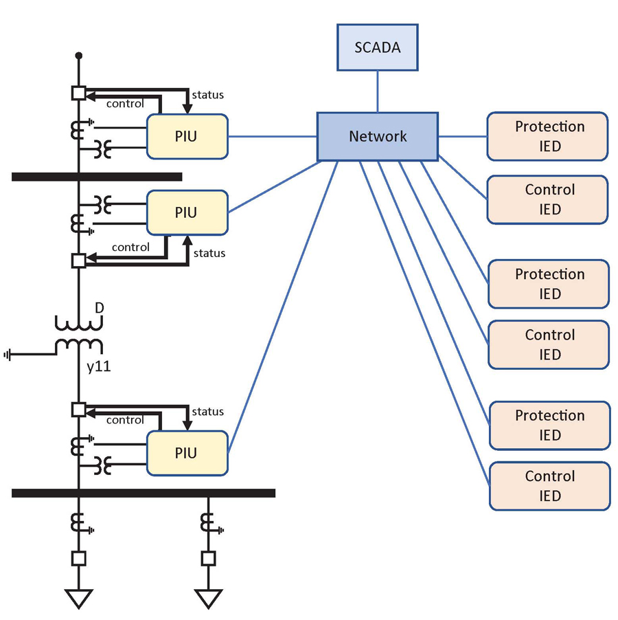
The architecture of digital substations is typically distributed as illustrated by Figure 1 with PIUs providing the interface between the primary substation equipment and all devices in the bay level over the substation’s local area network (LAN). The interfaces are based on GOOSE and sampled values (SV) messages. The interfaces between the multifunctional IEDs themselves are typically performed via GOOSE messages in the process or station bus. Finally, client/server communications over the digital substation’s station bus are used for the interface between the bay and SCADA level.
INTRODUCTION TO IEC 61850
The IEC 61850 series of standards defines not only a communication protocol — i.e., how bits and bytes are to be sent from one device to another — it also specifies different aspects of a whole communication concept. It goes far beyond many other communication standards.
IEC 61850 defines a standardized configuration language for system engineering as well as several specifications, guidelines, and features regarding the testing of IEC 61850 systems. The various defined aspects are:
- Data Model. Data that can be communicated via IEC 61850 is defined in the so-called data model. It specifies which information is available to be exchanged with other devices and how this data is to be stored.
- Communication Services and Protocols. Information provided in the data model of a device can be exchanged with other devices using several services defined by the IEC 61850 standard. Depending on the data transmission requirements, the amount of data, and the application, a specific service is to be used. Services are then mapped to a specific channel or medium for data transmission like mapping to Ethernet protocols.
- Engineering. The system configuration language (SCL) is specified to allow for the exchange of configuration information between various IED and system configuration tools.
- Testing. The standard defines how to test to verify whether a device is conformant to IEC 61850. It also provides several specifications for network performance testing. Moreover, it defines some features that are important for the functional testing of devices
Data Model
Data in IEC 618560-capable devices is stored in the data model in a standardized way. One function represented in the data model is called the logical node. Logical nodes are the central elements in a data model, as each one represents an elementary function of a device or the substation in general. Within a logical node, all information related to the function is stored in data objects and subsequently in data attributes that are strictly defined in the standard. The data model of an IED can contain dozens to hundreds of logical nodes, depending on the capability and functional scope of the IED. The data model has a hierarchical structure as shown in Figure 2. The physical device level is represented by the IED name, which is defined by the user during configuration. Logical devices are used to sort data out. They are typically defined by the IED manufacturer, but many IED tools allow the user to change them.
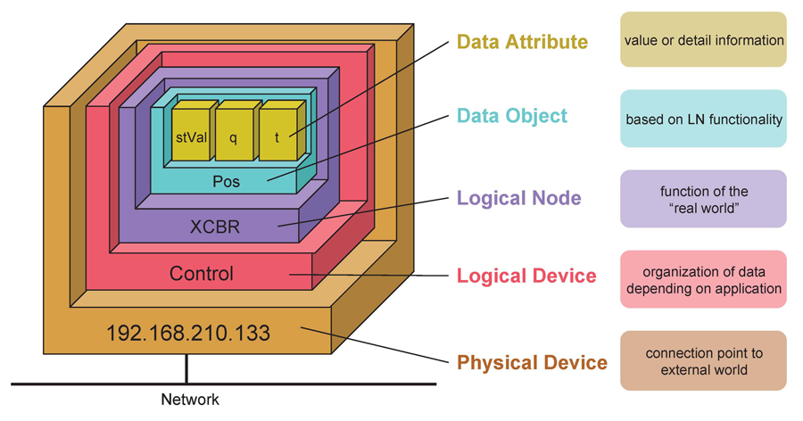
Figure 2 shows how the function Circuit Breaker is modeled as Logical Node XCBR in the data model of an IED. In this example, only one data object — the position (Pos) of the breaker — is shown. The breaker status (stVal) is double-bit information representing the 52a/b contacts of the breaker. The data is represented by its data path name IEDname.LogicalDevice.XCBR.Pos.StVal. In a digital substation, this data is typically present in the PIU interfacing with the breaker. For a protection relay, the general trip output can be represented by a PTRC type of logical node, where the trip attribute is called IEDname.LogicalDevice.PTRC.Tr.general. Vendor-specific naming and structuring of data is therefore replaced by a common naming and data structuring concept.
Figure 3 shows an example of some parameters configured in a conventional relay. The physical binary Input 1 (IN101) of the device is hardwired to the breaker auxiliary contact (52a) and is assigned to the relay internal variable called 52A_S. The transformer trip logic variable TRXFMR is mapped to the physical Output 1 (OUT101) of the relay, which is hardwired to the breaker trip coil.
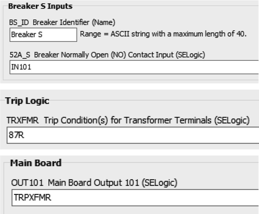
For an IEC 61850 implementation, the same IED will have only digital interfaces, and the data used will come from the IEC 61850 data modeling. Instead of 52A_S and TRXFMR from the example in Figure 3, XCBR.Pos.StVal and PTRC.Tr.general data are used for the communication configuration.
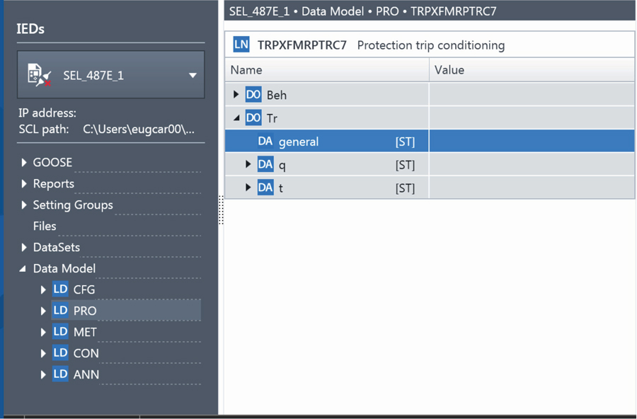
Figure 4 shows an example of a trip logic data attribute of an IEC 61850 transformer protection IED. The data is in the logical device PRO, and the PTRC logical node type was assigned a prefix (TRPXFMR) and suffix (7) to help identify the signal. The data’s full name is then PRO.TRPXFMRPTRC7.Tr.general. For conventional and digital IEDs, it is important for the tester to know the data structure and naming so they can easily monitor data status when testing or troubleshooting.
Now that we know how data is represented, let’s look at how this data is exchanged between the devices.
Protocols and Digital Interfaces
Three main communication services are defined in the standard to be used for PAC: client/server, GOOSE, and sampled values.
Client/server represents the services used by a client to retrieve information and send control operations to and from IED servers, forming a typical SCADA system for supervising and controlling the substation. For the implementation of such communication services, the standard defines the mapping and use of the multimedia messaging service (MMS) protocol. Testing tools can also make use of the MMS protocol and act as a client to retrieve status information from the IEDs or to send control commands to the IEDs during a test.
GOOSE is used for peer-to-peer communication and fast exchange of information between the bay and process levels and between IEDs in the bay level. It is a multicast Layer 2 message published by an IED over the network that can be subscribed to by any other IED connected to the same network. The message is repeatedly published, even when no changes occur, to increase reliability. With GOOSE, any real-time information (conventionally transmitted via binary outputs, copper cables, and binary inputs) can now be exchanged through the communication network.
Sampled values (SV) uses a multicast communication mechanism for the transmission of sampled current and voltage measured values from instrument transformers through the communication network. They are published by the MU (or PIU) interfacing with the secondary analog signals from CTs and VTs.
A conventional transformer protection relay is hardwired directly to both CTs on the high-voltage and low-voltage sides of the transformer. The relay is also hardwired directly to the breaker auxiliary contacts and trip coil. Figure 5 shows how this same transformer protection IED is implemented in a digital substation. The XMFR1_IED performs the protection functionality, but digital interfaces are built through the exchange of GOOSE and SV with the respective PIU. It measures currents from all CTs via SV subscription from multiple PIUs and sends a trip command via a GOOSE message to the PIU.
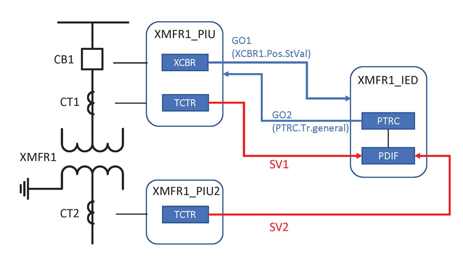
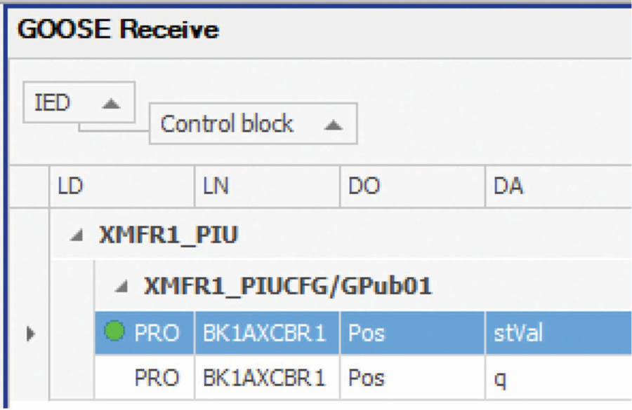
If breaker status is needed, it is acquired via GOOSE subscription to the message published by the PIU. A GOOSE subscription example is illustrated in Figure 6.
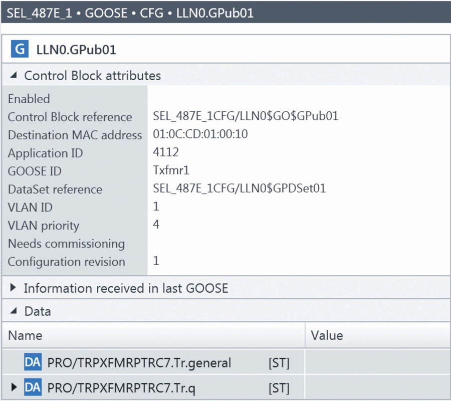
A trip GOOSE published by the IED is illustrated in Figure 7.
SCL Configuration Files
The IEC 61850 standard specifies a common, vendor-independent configuration concept. The machine-readable configuration information in an XML-based standardized format called system configuration language (SCL) is used in this process. Its main purpose is to allow the exchange of communication system configuration data between different configuration and testing tools in a compatible way.
The two main types of SCL files used by testing tools are:
- Substation configuration description (SCD) contains all configured IEDs of a project, their data, communication configuration, and all IEC 61850 aspects for a given system. This file is created by the system configuration tool (SCT).
- Configured IED description (CID) contains a subset of the SCD file with all information related to one specific IED.
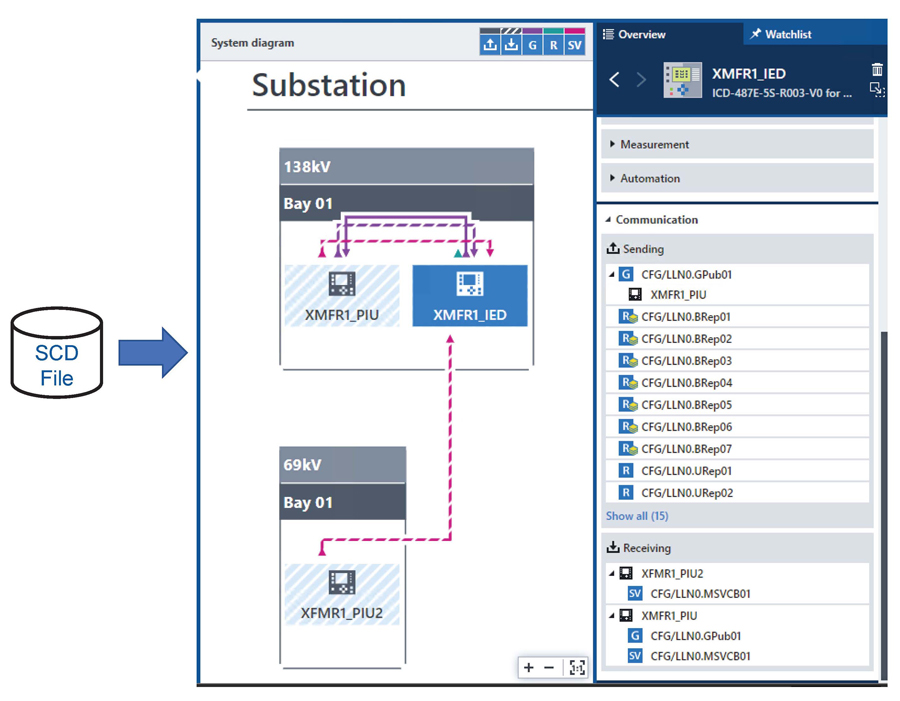
The SCD file is the ultimate file resulting from a completed IEC 61850 system design. The SCD file is used by engineering tools and for documentation purposes, as well as by testing tools (example in Figure 8). More details are available in Carvalheira and A. Klien.[2] When commissioning and testing an IEC 61850 digital substation, the SCD file should be part of the documentation package provided to the testing group along with other documents such as single-line diagrams and functional drawings.
PROTECTION TESTING STRATEGY
When defining the test procedures to validate protection relays and schemes, we must define which equipment will be part of the test. If the entire system is to be tested together, this could be accomplished by using primary injection to CTs and VTs to simulate fault scenarios and observe breaker operations to assess the system response. For testing protection relays, this approach is not entirely feasible, as it would require simultaneous primary injection in multiple CTs/VTs.
Another option is to use secondary injection to the MU and PIU. The test set would have hardwired interfaces only to the MU/PIU; therefore, this test is performed very similarly to conventional substations. Even though this seems to be an attractive option, this approach poses many challenges. The MU cabinet is typically located in the substation yard and for many test cases (e.g., a transformer differential relay), simultaneous injection to multiple MUs is required. When on-site during commissioning where multiple groups are working to install and wire the PIU cubicles in the substation yard, it is challenging to get all equipment available altogether. This test would only be possible at the very end of the installation; therefore, it is difficult to plan and it is not time efficient. For maintenance, it is also common that only the IED is taken out of service while the PIU is kept in service.
The best option is to separate the entire system into subsystems in which test coverage should overlap each other providing maximum reliability. The test would be divided by:
- MU/PIU testing
- Network testing
- Protection IED testing
Testing the MU/PIU involves the injection of secondary voltages and currents, and many of the traditional methods used in conventional substations apply. Validation of the digital interfaces requires new tools and is done similarly for the IEDs. This test is not specifically covered in this article.
Network testing can be divided into multiple activities. One is the validation of the network traffic itself, confirming all IEDs are publishing the configured messages and that all data is reaching its destination. This test is covered as part of the protection testing procedure. Testing of network performance such as bandwidth, latency, and redundancy is another aspect not covered in this article but is available in McCreery.[4]
The protection IED functionality and configuration are tested by isolating the IED from the PIU. The test set is configured to interface digitally with the relay. All incoming SV and GOOSE messages to the IED are simulated by the test set, while all GOOSE outputs from the IED are subscribed by the test for validation. Typically, the protection test procedures are divided into two activities:
- IED (relay) unit tests. The IED is completely isolated and tested as a single unit to validate its main settings and configurations. This is typically performed for all IEDs in the system.
- System (group) tests. A group of IEDs that are part of a protection scheme are isolated and tested simultaneously. For test scenarios where multiple IEDs are tested together, the actual communication interface between them is validated as part of the test and does not have to be simulated by the test set. The number of test scenarios and involved IEDs will depend on the schemes implemented in the project. In the example of Figure 5, if a breaker failure function is implemented in a separate IED, the breaker failure IED and the transformer protection IED could be tested together as a system when validating the breaker failure scheme. This article will focus on the aspects of IED unit tests. System tests are covered in more detail by Carvalheira and Wilson.[3]
Before exploring how protection IED unit tests are performed, we should investigate how to isolate the device’s digital interfaces.
IED TEST ISOLATION
The requirements for isolation in conventional hardwired substations are met using physical test switches that completely disconnect the device under test and the test equipment from the substation environment.
In an IEC 61850-based digital substation, such physical isolation is not possible because hardwired interfaces are replaced with communication messages. It is necessary to find another way to isolate. The IEC 61850 standard includes features that can be used to achieve what is known as virtual isolation. It is based on the appropriate use of the mode of the tested components, as well as the ability to distinguish between the normal messages over the communication network and the simulated messages published by the test system.
Mode and Behavior in IEC 61850
The behavior of the function elements in IEC 61850-based devices is controlled using the data object Mod defined in the standard. Five modes are available as described in Table 1.
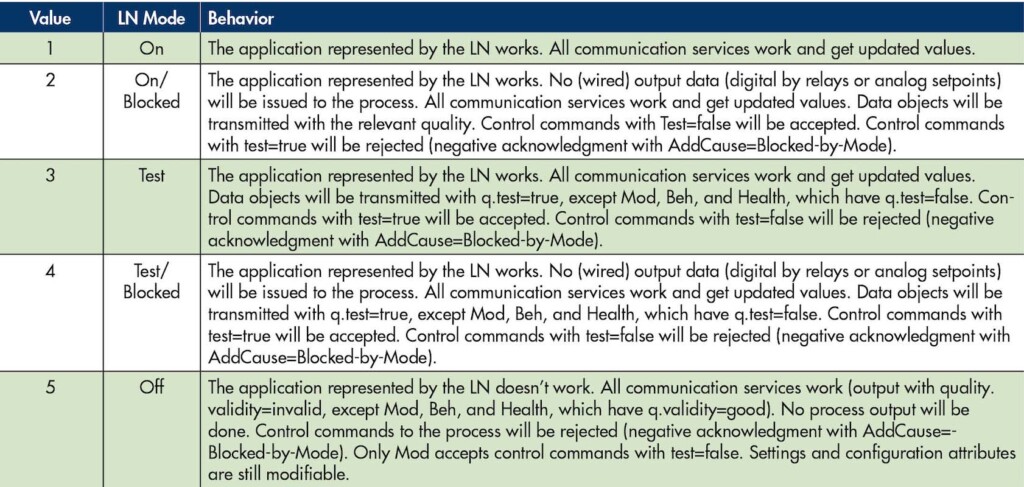
Table 1: Mode and Behavior in IEC 61850
From this table, it is clear that the isolation of the tested function is achieved by setting the mode to test or test/blocked. Depending on how it is implemented, switching between the modes (Mod.stVal) can be performed via a command from the test set or via a local action (e.g., a push button in the IED).
Even though the standard allows for individual functions (logical nodes) in an IED to be placed in test mode, a typical implementation is to have a single Mod data object controlling the entire test mode behavior of the IED.
When a device is put in test mode, all quality attributes of associated data objects are tagged as in test (bit q.test=TRUE). If a device is publishing data within a GOOSE message, the data quality should also be included in the GOOSE message so subscribers can check whether incoming subscribed data is from devices under test. Devices in operation (Mod=On) should ignore data coming from devices under test (Mod=test or test/blocked).
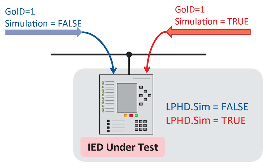
Message Simulation
Another feature gives the IED the option to subscribe to GOOSE or SV messages that are simulated by test equipment. GOOSE and SV messages have a flag indicating whether the message is the original message from an IED or if it is a message simulated by a test set (Figure 9). On the other hand, the IED subscribing to the message has a Sim data object in the logical node LPHD (logical node for the physical device) defining if the IED shall receive the original GOOSE/SV messages or the simulated one. If Sim is set to TRUE, the IED should subscribe to all GOOSE/SV messages that have the simulation flag set to TRUE. If no simulated message exists for a specific GOOSE message, it will continue to receive the original message. This feature can only be activated for the whole IED since the IED shall receive either the simulated message or the original message.
IED Isolation Process
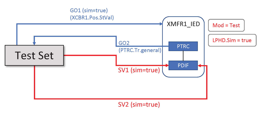
Combining the mechanisms described in the previous sections, it is possible to test a device that is connected to the system. Let’s assume we want to test the IED XMFR1_IED from Figure 5. The IED should first be put in test mode by setting the appropriate Mod virtual switch in the IED to either test or test/blocked. The IED continues functioning and publishing GOOSE messages, but it will now tag the quality of all its data as in test (bit q.test=TRUE). The test set can receive and process the data, but all other IEDs that are in normal operation will discard the messages. Referring back to Figure 5, the PIU will ignore any trip coming from the IED that is in test. This process then has the same outcome as physically opening the test-switch blade connected to the trip circuit in a conventional substation. Next, the data object Sim in the IED should be set to TRUE. The test set can start simulating the SV with the same identification as those normally received by the protection IED from the PIU but with the simulation flag in the message set to TRUE. The protection IED will now receive the SV from the test set and no longer from the PIU. This process has the same outcome as physically opening the test-switch blades connected to CT/VT in conventional substations to physically connect the test set.
IED UNIT TESTS
As explained previously, the IED is completely isolated and tested as a single unit for this test. The test set is connected to the communication network. The exact switch port connection point(s) is to be specified in the project documentation. The switch port should be configured to allow the traffic flow from/to the test set. Depending on the network topology, the test set needs to be connected to multiple network switches. This is typically the case when the project has separate process bus and station bus networks. Special attention is required when configuring the test set ports defining where the SV messages are to be published and where the GOOSE messages are to be published and subscribed. Also, if the test set is to establish a client/server MMS connection to the IED, the test set needs to be connected to the appropriate network, typically the station bus. Figure 10 shows the test set digital interface with the IED from Figure 5 (switches and network connections are omitted). There should be no physical intervention for the IED. Instead, the IED is isolated by setting the Mod and Sim virtual switches as explained in the previous section.
An IED unit test procedure (Figure 11) should include verification of:
- SV subscription mappings
- GOOSE subscription mappings
- GOOSE outputs
- Protection settings (e.g., pickup, time delays)
- Protection logic and schemes
- Control logic (if implemented)
- SCADA points
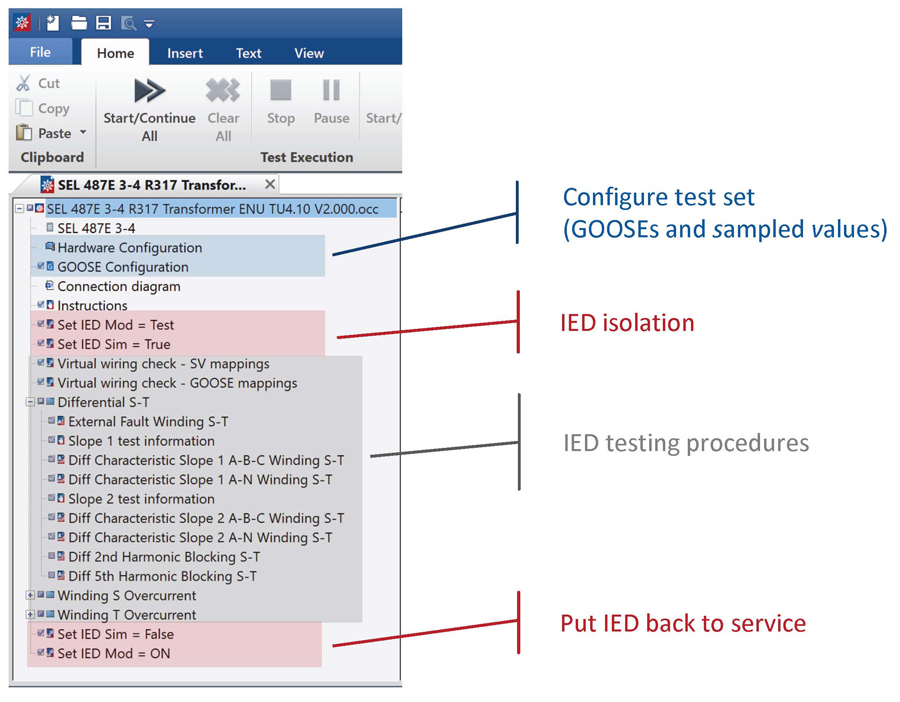
The SCL configuration files are used to configure the test. This represents a big advantage and allows for efficient test preparation and execution. Depending on the implementation, the process of isolating the IED can be executed by the test set itself and can be included in the test plan file in the test set software.
The SV subscription mapping validation is similar to the meter check performed in conventional relays. The test set injects voltage and current values and the IED metering is checked. Even though there is no risk of any physical miswiring, this test is important to validate that the virtual wiring of current/voltage signals was done correctly in the software.
Many of the GOOSE signals — inputs (subscription) or outputs (publishing) — can be verified while running the protection setting tests. For all other remaining signals, a specific test can be included to validate that they were correctly mapped in the software.
Testing the protection settings and logic is performed very similarly to conventional relays. The protection itself is the same; just the interfaces were replaced by digital ones. However, it should be noted that more extensive logic capabilities are likely to be found in digital IEDs. If compared with older conventional technologies, there is a trend to decrease the number of element tests that are performed and increase the amount of communication and logic tests.[3]
After the IED unit test is performed and the IED is put back into operation, proper communication of the IED with other IEDs and PIUs in the network should be checked. Alarms can be built into the SCADA system to give warnings in case a communication link is not established. The testing tool itself can also provide warnings and let the tester visualize the whole system with the status of each communication link. Figure 8 gave an example of how a testing tool can display the information. All communications links are known by the testing system from importing the SCD file, so the test system can sniff for messages in the network and also interrogate IEDs to check for subscription status.
CONCLUSION
Testing protection relays (IEDs) in digital substations is not substantially different than in conventional substations. The main difference is in how the test set interfaces with the IED by establishing the required communication links. However, testing personnel must be familiar with certain aspects of an IEC 61850 digital substation. This article discussed many of these aspects that are needed to commission and test such a system.
Knowledge of the new standard naming and data model structure is important when troubleshooting signals and trying to run IED diagnostics. A basic understanding of the SCL files and how to use them for the test configuration is also a requirement. Understanding how the IEDs are configured is also very important when defining which test procedures will be performed. It helps to focus the tests on those aspects that are more likely to be a source of misconfigurations and therefore more likely to contribute to a possible misoperation. The trend is to perform less element testing and more communication and logic tests.
Despite the initial learning curve that is part of adopting new technology, IEC 61850-based substations bring a lot of benefits that allow for overall better test quality and efficiency. Training of all stakeholders, including testing engineers/technicians, and familiarity with modern testing tools are key to success.
REFERENCES
[1] IEC. IEC 61850, Communication Networks and Systems for Power Utility Automation, Parts 6, 7-1, 7-2, 7-4, 8-1, and 9-2. [2] E. Carvalheira and A. Klien. “Simplifying the Testing of Automation and Control Systems,” NETA World, Summer 2021. [3] E. Carvalheira and G. Wilson. “System-Based Protection Testing in Digital Substations,” PACWorld, December 2021. [4] S. McCreery. “Digital Substation LAN Design and Testing,” NETA World, Summer 2023.
Eugenio Carvalheira joined OMICRON in 2008 as a Training and Application Engineer developing test automation solutions for protection relays, providing technical product application support, and being responsible for the IEC 61850 training courses at OMICRON. He is currently Engineering Manager for North America based in Houston, Texas. He is an active member of IEEE PES and serves on many PSRC and PSCC working groups. Eugenio has 20-plus years of experience in power systems protection, and automation and control (PAC). He spent part of his career as a project engineer responsible for the design, implementation, and commissioning of PAC systems at electrical substations and power plants. Eugenio received a BSc in electrical engineering from UFPE University in Brazil and an MSc in computational engineering from the University of Erlangen in Germany.