

Circuit breakers used in low-voltage applications include air circuit breakers, insulated-case and molded-case circuit breakers, and miniature circuit breakers. Air circuit breakers or low-voltage power circuit breakers typically function as the incoming device on a low-voltage switchboard. In the event of an overload condition or short circuit, current sensors in low-voltage power circuit breakers measure high currents and send the feedback to an electronic trip unit.
The trip unit is the brain of the circuit breaker; it causes the circuit breaker to act according to the logic programmed in the trip unit. The molded-case circuit breaker incorporates an electronic trip unit; however, in smaller frame sizes, the trip unit may not be as sophisticated as those found in air circuit breakers. Some MCCBs include an electromechanical thermal trip and electromagnetic trip in place of the electronic trip unit.
To properly isolate a fault, the circuit breaker must act in a timely and reliable manner. Failure of a circuit breaker to do so can result in a more widespread outage area, loss of revenue, damage to equipment, injury, or loss of life in a worst-case scenario. Hence, it is essential to carry out maintenance work at regular intervals throughout the service life of a circuit breaker. Various activities can be undertaken as part of preventive maintenance. This article focuses on electrical testing that can be carried out on low-voltage circuit breakers.
Testing Low-Voltage Circuit Breakers
ANSI/NETA MTS, Standard for Maintenance Testing Specifications for Electrical Power Equipment & Systems recommends the following electrical tests as part of maintenance testing on low-voltage circuit breakers:
Resistance Measurement
By measuring the contact resistance on each pole of the circuit breaker, we can check for contact-related issues that can interfere with the circuit breaker’s ability to conduct current adequately. For instance, contact erosion over time can lead to heating issues that eventually lead to breaker failure. Resistance values are typically measured in the range of µΩ, although resistance can exceed 1 mΩ in the case of some low-amp-rated MCCBs. As current rating increases, the resistance values measured on the poles typically tend to drop. Similar values should be measured on the poles of the same breaker, and any deviation of more than 50% warrants investigation. The breaker manufacturer can be consulted on the expected pole-resistance value.
Insulation Resistance Measurement
Insulation resistance can be measured between phases and between phase-ground with the breaker closed and across each pole with the breaker open.
Primary Injection Testing
Primary injection testing involves injection of current through the poles of the circuit breaker to verify that the breaker will operate as per the trip unit logic. Four tests can be carried out:
- Long-time delay and pickup. The long-time delay characteristic provides overload protection. The pickup is typically set equal to the overcurrent protection device’s continuous current rating. The test current injected is typically three times the long-time pickup. The test current is injected through each pole, and the trip time is recorded each time. The results are validated by referring to the time-current curves provided by the manufacturer. The trip time recorded is typically in the order of seconds to avoid spurious tripping.
- Short-time delay and pickup. The short-time delay characteristic provides protection against short-circuit or fault conditions. An intentional delay is provided for coordination or selectivity with other protection devices. The short-time pickup is a multiple of the long-time pickup. The test current typically used is 1.5–2.5 times the short-time pickup. The test current is injected through each pole of the breaker and the trip time is recorded each time. The results are validated by referring to the time-current curves published by the manufacturer (Figure 1). The trip time recorded is typically in the order of cycles or milliseconds.
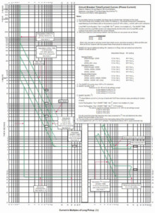
Figure 1: Sample Time-Current Curve from a Manufacturer
- Instantaneous pickup. The instantaneous trip characteristic provides protection against short-circuit or fault conditions but doesn’t include any time delay. In this test, pulses of current (pulse duration between 5 and 10 cycles) with steadily incrementing magnitudes are injected through each pole until the circuit breaker trips. The starting pulse is set at around 70% of the expected pickup. The value of the pickup at which the breaker trips is recorded. Manufacturers typically provide a tolerance of ±10% to ±25% on the pickup.
- Ground-fault delay and pickup. The ground-fault trip characteristic provides protection against ground faults. The ground-fault pickup is typically a fraction (20%–60%) of the continuous current rating of the overcurrent protection device. The test current injected is typically 1.5–2.5 times the pickup. This test is required for many service entrances by NFPA 70, National Electrical Code (NEC 230.95).
Primary Injection Test Procedure Factors
Several factors must be appropriately determined for a successful test.
Input Specifications
The output of the primary injection test set depends on the input voltage. It is essential that the input voltage provided should be within ±5% of the specifications for the test set. The input breaker must be sized appropriately. As the test set is operated at higher currents, higher losses occur. As a result, the relationship between the input current and the output current for primary injection test sets is exponential (Figure 2). When procuring a high-current test set, it is important to install an input breaker that is sized to handle the input power required for the maximum test currents that would be applied in the course of testing the breakers.
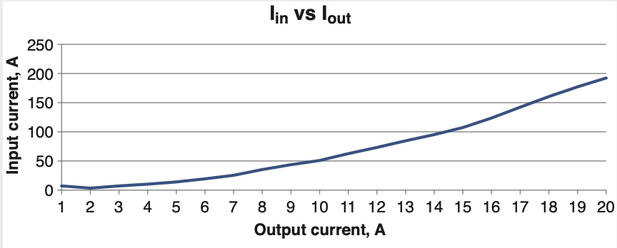
Figure 2: Input Current Measured for Primary Injection Test System at Various Output Currents
The connection leads between the input voltage supply and the input voltage terminals on the test set also must be appropriately sized and short in length. Unnecessarily long connections can result in a drop in voltage at the input voltage terminals, thus affecting the performance of the test set.
Test Connections
As high-current test sets have very-low open-circuit voltage (typically 5–10 V), the maximum output from a high-current source is limited by the circuit impedance, which in turn primarily depends on the test connections. For lower-amperage breakers, the connection is typically done using cables. These cables need to have sufficient ampacity. This can be achieved by connecting multiple cables in parallel. The shortest possible cables should be used. The cables can be twisted together whenever possible to further reduce the impedance of the circuit.
High-current test sets used for testing draw-out-type circuit breakers use stab sets for connections to ensure the circuit impedance is negligible. Stab sets of various designs can be created for use with different types of circuit breakers.
To overcome high circuit impedance while testing at relatively lower currents, some high-current test sets have a modular design that allows multiple high-current sources to be connected in series to achieve a higher open-circuit voltage to drive the desired current through the breaker.
DC Offset
During an instantaneous trip test, an error can be introduced into the result because of the presence of a DC offset in the current pulse (Figure 3).
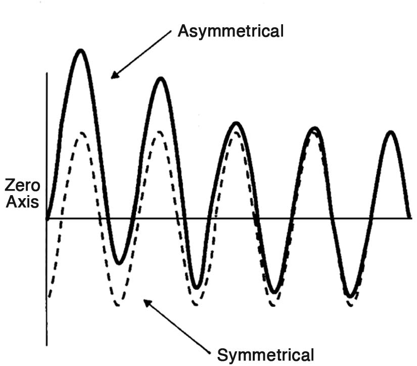
Figure 3: DC Offset as Shown in NEMA AB-4
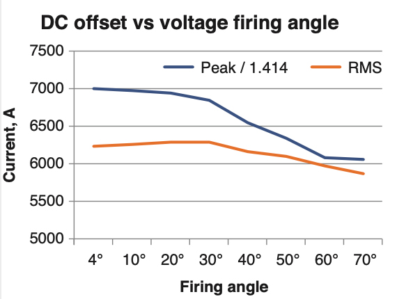
Figure 4: Difference between Peak/√2 and True RMS Value Observed in Output Current for Various Firing Angle Values
The asymmetrical nature of the first few current cycles results from a high X/R ratio in inductive circuits. The DC offset can be minimized by manually or automatically adjusting the firing angle (the point on the voltage wave at which the output is energized). A measure of the DC offset is the difference between the peak/√2 and RMS (Figure 4, Figure 5, Figure 6, Figure 7). They should be equal for a perfectly sinusoidal wave.
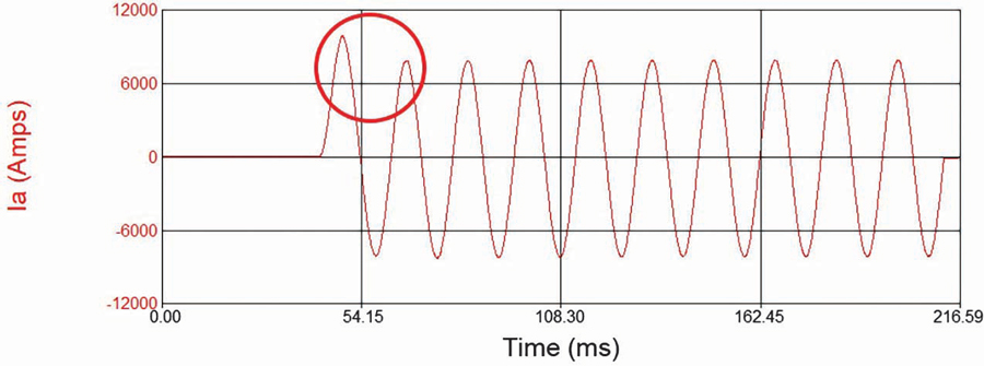
Figure 5: Current Waveform at Firing Angle of 4 Degrees
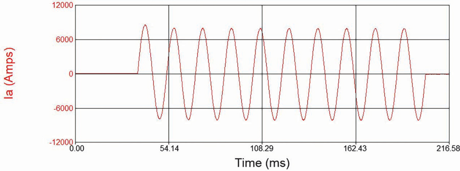
Figure 6: Current Waveform at Firing Angle of 70 Degrees
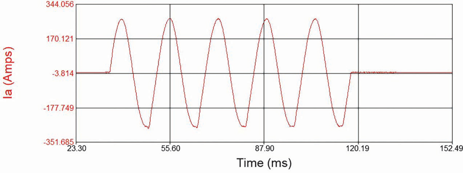
Figure 7: Current Waveform with Automatically Adjusted Firing Angle
Ground-Fault Protection on Trip Unit
While testing circuit breakers equipped with trip units having ground-fault protection, it is important to disable the ground-fault protection to be able to run the other tests, as the currents involved in other tests tend to be higher than the ground-fault pickup. While some trip units provide the option of disabling ground-fault protection, a breaker without that option can still be tested by injecting current through two poles connected in series as shown in Figure 8.
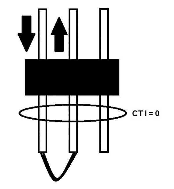
Figure 8: Two Poles Connected in Series to Bypass GFP on Trip Unit
Selecting a Primary Injection Test Set
Primary injection testing has been done for decades. The traditional technology is still relevant, along with the introduction of newer technology with some advantages.
Primary injection test sets are available in various sizes depending on the output current range. Primary injection test sets used for testing power circuit breakers are typically large and weigh hundreds of pounds.
Primary injection test sets that operate at relatively lower currents can be mounted on carts, which enables testing outdoors in substations, for example. Still smaller portable primary injection test sets can put out current in the range of a few thousand amps. Having a portable test set certainly helps if testing needs to be done in elevated or difficult-to-access locations.
As mentioned earlier, primary injection test sets may have a modular design that provides the tester with some flexibility in achieving different output currents and output voltages. Higher currents can be achieved by connecting multiple sources in parallel, whereas a higher open-circuit voltage can be achieved by connecting multiple sources in series.
Some primary injection test sets include additional features like secondary measurement channels. This enables them to be used in other applications such as CT ratio testing or measurement of other parameters (Z, R, ,
etc.) in a circuit.
Traditionally, output current control has been done manually, but newer technology permits automatic current control. This eliminates the additional step of adjusting the output setting to achieve the desired current prior to starting the test, as well as the need to manually adjust the output current to maintain a certain level during a long-time test.
Software with a library of time-current curves from various manufacturers means the user doesn’t have to spend time finding and then interpreting the manufacturer’s published time-current curves to determine the trip-time limits for a certain test.
The wide variety of primary injection test systems offers an informed choice based on multiple factors including portability, ease of use, size of breakers to be tested, and magnitude of test currents.
Conclusion
Primary injection testing is the complete test for a circuit breaker. It verifies the entire protection chain in a circuit breaker. The current flows through the pole(s) of the circuit breaker, thus verifying the current-carrying path. The current sensors and wiring are checked. The trip unit logic is verified. The operating mechanism of the breaker is also tested. Thus, it can be said that it is a complete test of the circuit breaker.
References
National Fire Protection Association. NFPA 70, National Electrical Code (NEC 230.95). Quincy, Massachusetts.
National Electrical Manufacturers Association. NEMA AB 4-2017, Guidelines for Inspection and Preventive Maintenance of Molded-Case Circuit Breakers Used in Commercial and Industrial Applications. Arlington, Virginia.
 Sanket Bolar is a substation applications engineer at Megger. From the beginning of his professional career, Sanket was directly involved with testing and condition assessment of power transformers working for Siemens Ltd (India). While working on his MS, Sanket became part of Megger’s internship educational program. Upon graduation in 2015, he joined Megger as an applications engineer covering a broad spectrum of substation products from transformer to power quality applications. Sanket graduated from Mumbai University, India, in 2009 with a BS in electrical engineering and received his MS in electrical engineering specializing in power systems from North Carolina State University in 2015. He is a member of IEEE.