

A test technician’s toolbox can never have too many options. The more ways we can detect or confirm a problem in a piece of equipment, the better.
Early in my career at Duke Energy, I was never satisfied with just one test result indicating a problem, and I often second-guessed myself as to whether the equipment was bad or if I had performed the test improperly. So I would repeat the test, more to prove to myself the test was performed accurately than to check for different results.
Later working for Doble Engineering, I learned they kept statistical records on testing procedure quality. To my surprise and confirmation of my theory, I found an exceptionally large proportion of test results showing that bad equipment was, in fact, due to poor testing procedures. Bad test gear accounted for a much smaller proportion of bad tests, and a very small slice of the pie was truly bad equipment. That solidified my opinion that test technicians need advanced training on more than one way to prove a piece of equipment is at fault.
I regularly tell our technicians we are married to the Ability Sisters: liability, accountability, and credibility. Thinking about each one, every technician can relate to jobs where they verged on violating one or more of the sisters. Any violation can have serious consequences.
Competition in the testing business is tough. Maintaining yourself and your company as a customer’s trusted advisor takes diligence in testing, but most important is being able to provide accurate testing results and peace of mind so you feel good about the results when you walk away from the job.
When a job called for testing low- and medium-voltage breakers in the past, the only qualitative dielectric tests performed were contact resistance and insulation resistance. Sometimes, a customer would require a high potential test in addition to the insulation resistance test. This was strictly a go/no-go test rather than a qualitative analysis where the test tech could assess where on the lifeline a piece of equipment resided. A good test tech could tell by the numbers on the milliamp gage whether the specimen was close to failing or not; however, in reality, if the test set did not trip, the test was considered good.
When I discovered the benefits of power factor testing, I began to apply the test to medium-voltage breakers and discovered a much more accurate means to determine breaker health. With a little training, a technician can determine where the problem lies, how to isolate the problem, and finally whether the breaker can be repaired in the field or needs to be removed and taken to the shop.
BREAKER DIELECTRIC MEDIUM
Breakers can be categorized into voltage classes and the types of dielectric medium they use to extinguish the arc; each type has its individual set of problems. Breakers can further be broken down into the composition of the insulation components: plastic, fiberglass, porcelain, epoxy, or wood. Each material has its own set of dielectric constant characteristics, as do the dielectric mediums of air, SF6, and oil. A well-trained technician understands the differences in the leakage currents found when testing fiberglass versus porcelain or wood and knows if it’s likely he can cure the problem in the field. For example, leakages found on porcelain can be cleaned away in most cases since the cause is commonly contaminants on the surface. In wood, the cause can be surface contamination, but it is more likely moisture ingress, and the leakage current is traveling through the wood rather than on the surface. Knowing which test to run will point the technician to the problem rather than just showing there is a problem.
POWER FACTOR
To use power factor testing for breakers, the setup is similar to the insulation resistance test. The technician tests each pole piece or bushing, as I call them, with respect to ground since this makes up the largest percentage of the leakage path. In the last three tests, the technician measures only the current from the bushing under test to its mating bushing looking for leakage line to load. If all tests well, this concludes the required tests. But if the breaker tests bad, the following tests provide the answers needed to determine whether the breaker can be field repaired.
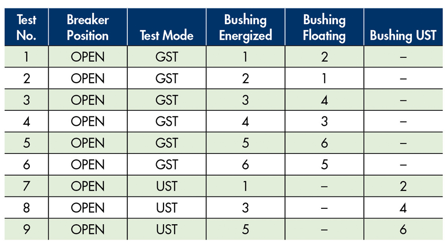
Table 1: Doble Test Procedure for Circuit Breakers
GST and UST Test Modes
The first six regular tests in Table 1 are in grounded specimen test mode (GST), meaning the test measures from where the hook is connected to ground by any path and returns through the measurement meter through the large copper ground cable. Be sure to have a clean connection where the ground clip attaches to the frame of the breaker since this is the test result return path. This test yields the highest leakage path. Comparing the readings points to a bad bushing, but if all readings are high, the question becomes whether that is normal for that type of breaker or if all six bushings are leaking to ground.
Some software provides breaker algorithms that compare the specimen under test to known breakers of like type. This provides a reference to what the readings should be. In many cases, no comparisons are available, so the technician must do further testing to determine health. The final three tests are conducted in ungrounded specimen test mode (UST) and measure the leakage current across the open bushing line to load.
Arc Chute Tests
The next step is to isolate various parts of the breaker to see if the test results change. This is not the easiest test to perform, but for accurate testing, arc chutes must be removed. Most arc chutes are constructed of materials that are hygroscopic, meaning they absorb water readily and provide a large path to ground. Many arc chutes contain asbestos, and care should be taken not to cause any material to become loose and airborne.
After removing the arc chutes, the same nine tests are repeated, paying special attention to the last three tests performed in UST. If the breaker now tests good, the leakage path is due to wet chutes, and they must be placed into a drying oven to resolve the problem. If the chutes are dry and therefore are not the leakage current path/paths to ground, more testing is required.
Diagnostic Test Mode
The next tests are done using the diagnostic test mode and open breaker. The test technician now adds a low-voltage lead to the opposite bushing, performs GST guard, and looks for a reduction or no change to the leakage (Photo 1). If the leakage is smaller, the mating bushing is a suspected source of the leakage.
Looking for Reduced or Unchanged Leakage
If the leakage result is the same, the technician adds a conductive band around the same bushing the hook is attached to (Photo 2), then attaches a clip lead between the band and the guard ring on the hook, and runs the UST test isolating the two bushings away from the other four.
UST Test Isolating Bushings
If the readings improve, the leakage current is moving along the surface of the bushing and normally is field repairable by cleaning and drying the surface of the bushing with a heat gun and then applying a good wax such as Collinite® The test is then reversed by energizing the mating bushing and determining the leakage current change. Very seldom will a test tech find just one bad bushing unless it is cracked or damaged in some way; most often, they all test bad. This is due to the environment they are housed in. A check for cubicle heaters should be completed and written up as a needed repair if found bad or missing.
The technician continues the testing by repeating the tests on all six bushings. Once the tests are completed, a comparison of the test results should be accomplished.
NOTE: The UST test is my personal favorite. When using it, the test set only looks at the leakage between the hook and the low-voltage lead being used. This test totally eliminates any other leakage source or path and provides the test tech information on just the two points between the connections. It provides exact data on the area of interest and can be connected between any two points.
Once a technician uses and understands power factor and sees the benefits, they can develop other tests they see beneficial and add them to the test list of any device — not just circuit breakers.
ENVIRONMENTAL ISSUES
Circuit breakers are often located in poor environments with contaminants from the production line and elsewhere. Thinking about what is being produced helps a technician understand the potential problems. A material that is conductive or absorbs water readily is going to be more of a hindrance to testing than a material that is inert and does not stay suspended in the air long. Knowing the material gives the technician a good idea what to expect when they begin testing.
This brings us to a continual argument between techs and test companies. Is testing performed as found, or is the testing performed after the breaker is cleaned thoroughly? Two trains of thought emerge:
- Testing in the real-world environment where the breaker must operate day to day provides the worst-case conditions, and so it is obvious more failures will show up.
- Testing after cleaning (my preference) largely eliminates the effects of the environment and points to true failure modes in the breaker.
Unfortunately, the customer’s work scope document dictates which test(s) will be performed.
COMPARING POWER FACTOR DATA
This section compares a breaker with arc chutes to the same breaker without arc chutes.
Power Factor Test: Arc Chutes Installed
The actual power factor of the breaker is not as important as comparisons of watts loss, leakage current, and capacitance. Power factor is a function of watts and current and will vary as they do. It is more important to compare the watts losses between bushings of like tests. Watts losses are typically derived from the resistive element and should be very close in a good breaker. As contamination and moisture are introduced to the breaker, watts losses increase. Leakage current measured in mA should also be consistent and typically changes as deterioration and contamination change the physical characteristics of the breaker. In this test result (Figure 1), we see consistency in the mA current measured, but some variations in watts losses. Doble considers these acceptable until the open UST test is performed. If the leakage current and watts losses are higher than expected, this is a sign of wet arc chutes when only the UST line-to-load test are in question.
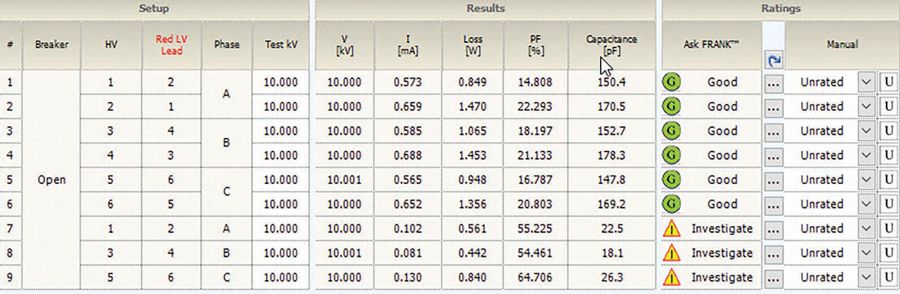
Figure 1: With Arc Chutes
Power Factor Test: Arc Chutes Removed
Once the arc chutes are removed (Figure 2), the first six lines change very little because it is not the actual bushings of the breaker passing the leakage current. In lines 7–9, the current and watts losses both return to low levels with a slight negative power factor due to the remaining resistive watts loss. This is not uncommon. Notice the consistency of the capacitances. The breaker is otherwise in good shape; it just has wet arc chutes.
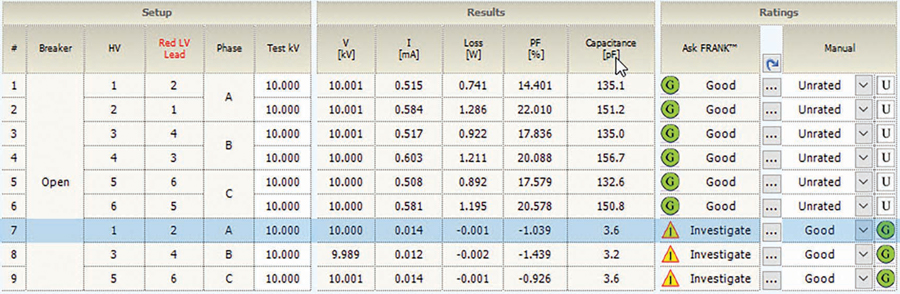
Figure 2: Without Arc Chutes
Doble still rates them Investigate, but now the rating is because the change between the first and second set of tests is so large. If the test tech instructs the software not to use test 1 as a comparison, the second set of results will show Good on all test lines. Seeing the values and knowing why the software rated the breaker as Investigate, the tester rated them manually to Good.
NOTE: One common question ask by technicians is why the watts losses on bushing 1,3 and 5 are similar but do not match the higher levels of 2,4 and 6. The short answer is that the connection of the operating arm to the moveable bushing arm adds a leakage path to ground on the higher measured set of bushings. This causes an increase in mA and watts loss and therefore capacitance. These should be similar and considered.
Power Factor Test: Bad Bushing
In this breaker (Figure 3), the obvious bad bushing test made it easy to isolate and identify the major problem, but the technician still must determine whether the other results are bad or normal for this breaker. Comparing like bushing watts is the first step. Bushings 2,4 and 6 are rated Good and are consistent at 0.5+ watts. The bad bushing lines 1,3 and 5 results are slightly harder to judge because there is no matching pattern in the watts. An investigation into why bushing 1 readings are so much lower would then be required. Using the UST tests in lines 7,8 and 9, the comparisons of 1,2 and 5,6 are close. This leaves the possibility that the watts loss in bushing 3 is higher than normal and bushing 5 cannot be used for any comparisons. Once bushing 5 is repaired and the breaker is cleaned, bushing 3 should be lower and the comparisons should be much closer. Final testing will determine whether this breaker is ready to go back in service or if further work will need to be done.
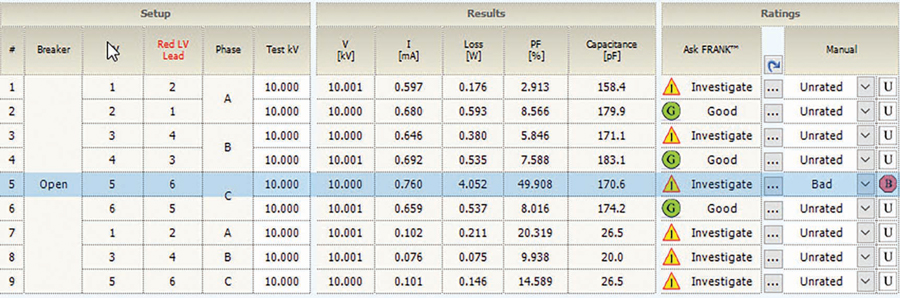
Figure 3: Bad Bushing
Power Factor Test: Wet Breaker/Bushings
In Figure 4, the initial tests, which would be GST measuring all six bushings to ground, showed apparent high leakage. But when lines 7–9 are tested in UST, the test tech is only measuring the leakage across line to load, and the tests are good even though lines 5–6 are 10 units different in watts and mA and therefore capacitance, too!
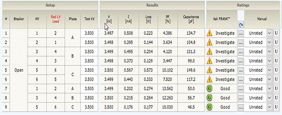
Figure 4: All six bushings will seldom test equally bad unless wet or contaminated.
Same Breaker After Drying
After drying, the same breaker has interesting test results (Figure 5) but not what would be anticipated. The watts losses would be expected to drop and pF would improve. Moisture is not the only type of contamination that causes bad results, so in many cases, the watts do not drop as expected after drying. This breaker may need further cleaning. The balance of the 1,3,5 and 2,4,6 watts and mA are closer. Therefore, the software changes the ratings to Good.
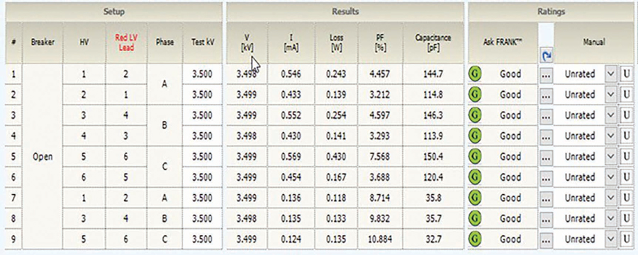
Figure 5: Dry Bushings
Power Factor Test: Good Breaker
As can be seen in this set of test results for a good breaker, the saying “It’s good if it tests below 0.5%” is not accurate for breakers. Confirming that the watts, milliamps, and capacitance are in balance defines a good breaker.
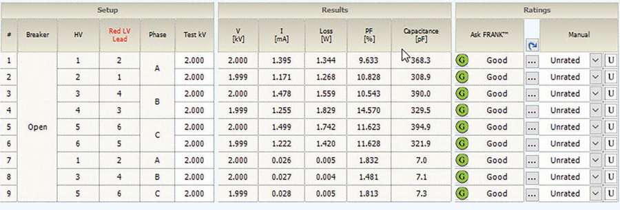
Figure 6: Good Breaker
Vacuum Breaker Test
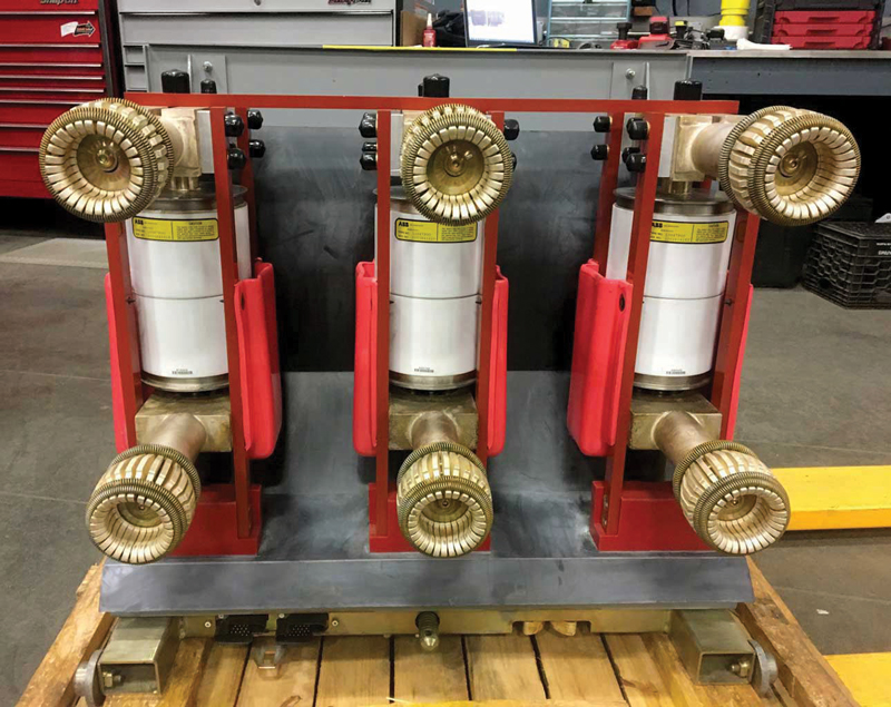
The sequence of tests on vacuum breakers is basically the same as on air magnetics, but the test tech must recognize some common problems that can and do affect the test results. The most common occurs during the UST check in the open breaker mode (Photo 3) when testing line to load: The technician appears to have interrupter failure due to very high leakage across the bottle. Most often the interrupter bottle is not bad but is conductive across the surface of the bottle due to electrostatics causing dirt and manufacturing product to collect on the surface of the interrupter.
UST Check in Open Breaker Mode
A very good cleaning and waxing with Collinite® will typically remove the conductive path and the bottle will test good. If it does not, the next test is to place a hot-collar strap around the middle of the bottle and guard off any leakage that is passing across the surface of the bottle. If the test is good, then a second cleaning is required.
If the test still shows a current path and the breaker has a mechanical jumper between line to load, it will need to be either removed or guarded out to ensure the leakage path is not through it. If the path is found to be through the strap, it must be dried in an oven or replaced. Finally, if the leakage across the bottle remains after all the possible paths have been removed, the leakage path is internal and the bottle will need to be replaced before a failure occurs.
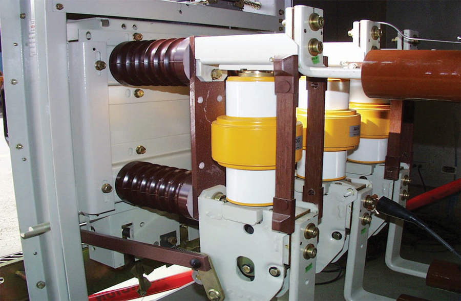
The second most common problem in a vacuum breaker is conductivity in the fiberglass shields between bushings similar to grids in an air magnetic breaker (Photo 4). Over a period of time, the fiberglass can absorb water and conductive contaminates that will contribute to poor tests. Typically, the method to determine whether the fiberglass is conductive is to remove it or guard it out. The test tech must be creative as to how they eliminate each obstacle to proper testing.
Vacuum Breaker
CONCLUSION
The PF column should not be used to judge any breaker. The use of watts, mA, and capacitance as the comparators provide the most accurate information. As shown, it is normal for some variation in test results from bushing to bushing, and the moveable bushing set will generally test differently — typically higher — than the fixed bushing set. Finally, using UST to localize problems is most helpful when isolation is needed. Lastly, adding one more tool to the technician’s toolbox provides peace of mind that accurate analysis and test results were given to the customer providing the credibility to maintain your customer’s allegiance for another year.
 Rick Youngblood is responsible for utility contracts as well as in-house training for all technicians at Electrical Maintenance and Testing, which is now owned by Potomac Electric, a NETA member company. After leaving active-duty Air Force, Rick finished his engineering degree at Purdue University and worked for PSI Energy as a Project Engineer responsible for substation maintenance and testing. He finished his 25-year career with Duke Energy as Manager of Substation Services responsible for all aspects of substation maintenance and testing. After retiring from Duke, Rick and his partner opened up a branch of American Electrical Testing in Indianapolis concentrating on utility business; here, he earned NETA Level 2 and Level 3 Technician certification. Rick retired a second time after seven years and closed the Indianapolis division of AET. Finding retirement unsatisfying, Rick became a Client Service Engineer for Doble Engineering, where he again dealt with all utilities from a training perspective for the Great Lakes region.