

Installed wind power capacity in the United States has been growing at an incredible pace during the last two decades. In the middle of 2020, the total American wind power capacity was nearly 110,000 MW with over 60,000 turbines installed (Figure 1).
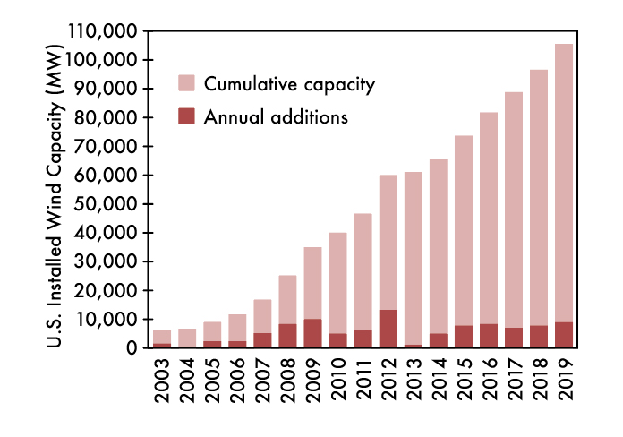
Figure 1: U.S. Wind Capacity in 2019
It is known that power equipment used to connect renewables faces very specific and increased stress when sources of fluctuating nature are involved. Large-scale wind and solar power often utilize transformers of different types within one installation. A typical wind farm electrical installation includes several small transformers (referred to as generation transformers in this article) connecting single wind turbines to a main bus feeder. Several feeders then connect the substation to the power grid using one or more larger power transformers.
For a better understanding of typical topology, please refer to Figure 2. While these power transformers typically do not show reduced life expectancy compared to other grid transformers, a higher rate of failures has been reported for generation transformers installed in wind farms, including liquid-filled as well as cast-resin transformers. The latter are widely applied when special measures for fire or ground water protection are required.
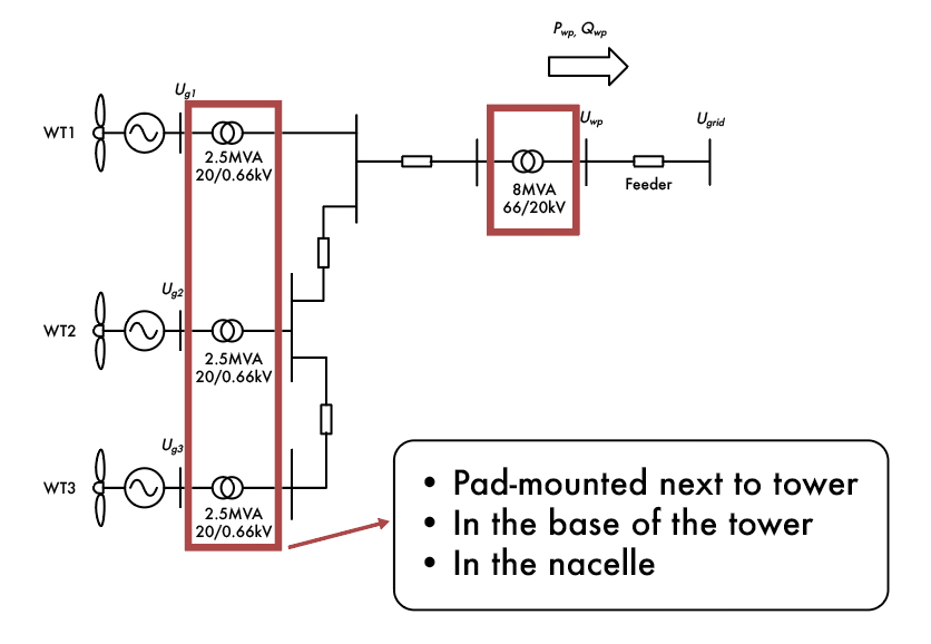
Figure 2a: Typical Topology of a Wind Farm
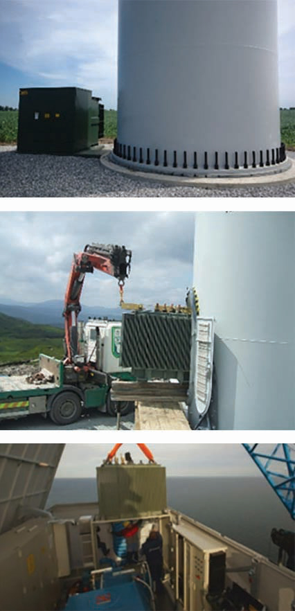
Figure 2b: Typical Topology of a Wind Farm
Generation transformers used in wind power plants typically have rated power ranging from 1 MVA to 4MVA, with primary voltages usually below 1,000 V and secondary voltages of up to 36 kV. Larger units with rated power up to 14 MVA are also available, but their failure rates seem lower.
In most cases, problems occur in the insulation system. Identified reasons include overheating due to very narrow design restrictions, vibrations, frequent thermal cycling, impact of frequency converter signals, high humidity, and salty air. Consequently, periodic diagnostic condition assessment is requested more frequently, as failures cause increasing outage costs for repairs and, often even worse, undelivered energy.
For cast-resin transformers, the application of typical diagnostic tools is very limited due to the specifics of molded, air-cooled windings. The most common reason for failure of this type of transformer is electric breakdown of the epoxy-resin insulation. Therefore, including off-line partial discharge measurements during commissioning and in a periodic maintenance plan can reduce the risk of in-service failures.
PD measurements on transformers can be quite challenging when performed onsite. If done online, the level of interference is usually above the permissible limit of a factory test. Therefore, PD occurring below the noise floor can go undetected. On the other hand, the logistics to perform offline PD measurements on transformers installed in remote and constricted space locations, such as wind farms, can be very complicated.
This article shares a modern method to perform offline PD measurements using induced voltage on medium-voltage transformers installed in the field in challenging environments such as remote locations, constricted space conditions, and areas with high electromagnetic interferences.
MEASURING PARTIAL DISCHARGE IN TRANSFORMERS
Partial discharges are localized dielectric breakdowns of a small portion of an insulation system under electrical stress. It can occur in solid, liquid, and gaseous electrical insulation. Most insulation systems used in transformers are not resistant to PD, and sustained PD activity will therefore result in erosion of the insulation. Over time, this can lead to in-service failures.
Accurate PD measurement can help identify weak points within the insulation system before complete insulation breakdown. For this reason, many international standards require or recommend PD measurements during the production of various MV and HV equipment. Commissioning and preventive maintenance of equipment during its service life is also increasingly recommended.
PD measurement may be performed on the windings of all types of dry-type transformers. For transformers with solid-cast windings with rated voltage above 1.2 kV, partial discharge measurements are an integral part of the routine tests performed at the end of the manufacturing process. The measurement is done during the induced voltage test by applying voltage to the low side of the transformer and measuring PD on the high side. Unlike the conventional applied voltage test, commonly called hipot, the induced voltage test stresses both the turn-to-turn insulation and the insulation to ground above the rated voltage.
In order to increase the test voltage above the rated voltage of the transformer, the frequency must be higher than 60 Hz to avoid core saturation without introducing significant interference pulses that may be detected as PD signals. In addition, the voltage source must be powerful enough to supply the needed reactive power at higher frequencies. Traditional voltage sources used in factories include large motor-generator sets (MG sets) or frequency converters. On many occasions, a capacitor bank is also used to compensate completely or partly for the needed reactive power.
PD test procedures are described in IEEE C57.12.91, IEEE C57.124, IEC 60076-11, and in IEEE C57.113 in the case of liquid-filled transformers. In dry-type transformers, a phase-to-phase pre-stress voltage of 1.8 x Ur is induced for 30 seconds, followed by a phase-to-phase voltage of 1.3 x Ur for 3 minutes, during which PD is recorded. For in-service or aged transformers, the voltage level is usually reduced to 80% of the factory acceptance test (FAT) level. The maximum level of PD must be less than 10 pC for solid cast windings and 50 pC for resin-encapsulated windings. As an example, the test sequence according to IEEE C57.12.91 and a three-phase connection diagram according to IEC 60076-11 are respectively illustrated in Figure 3 and Figure 4.
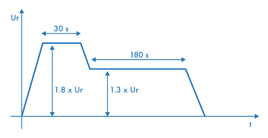
Figure 3: PD Test Procedure According to IEEE C57.12-91
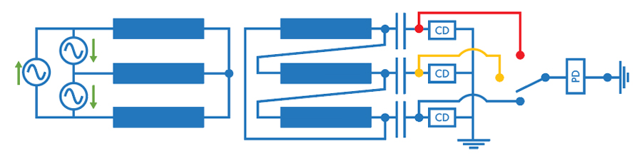
Figure 4: PD Test Arrangement According to IEC 60076-11
FROM THE FACTORY TO THE FIELD
For onsite PD measurements on transformers, the expectations for a voltage source are raised. In addition to the previously stated requirements to perform induced voltage tests at the factory, the voltage source must be able to function on the limited power available from a regular power outlet, as mobile diesel generators are not always available and must be portable for confined space conditions. A great example of such a space requirement is when testing a transformer installed inside the tower or the nacelle of a wind turbine or installed deep inside a facility with difficult access.
To reduce the power requirement, the onsite test is performed using a single-phase voltage source. The required power is therefore significantly reduced compared to the conventional three-phase test. In addition, energizing one phase at a time is usually the next step when PD is detected during a three-phase measurement. To further reduce the required power, a modern voltage source that can freely control the frequency and that can measure the impedance of the complete test circuit is used. The test frequency can therefore be tuned to the resonance frequency of the given test circuit, including the inductance of the transformer, the winding capacitance, and the coupling capacitor used for PD measurement. Figure 5 illustrates an example of the frequency response of such a system. If the test frequency is set to the maximum value in the blue curve (highest impedance), the required test power is minimized.
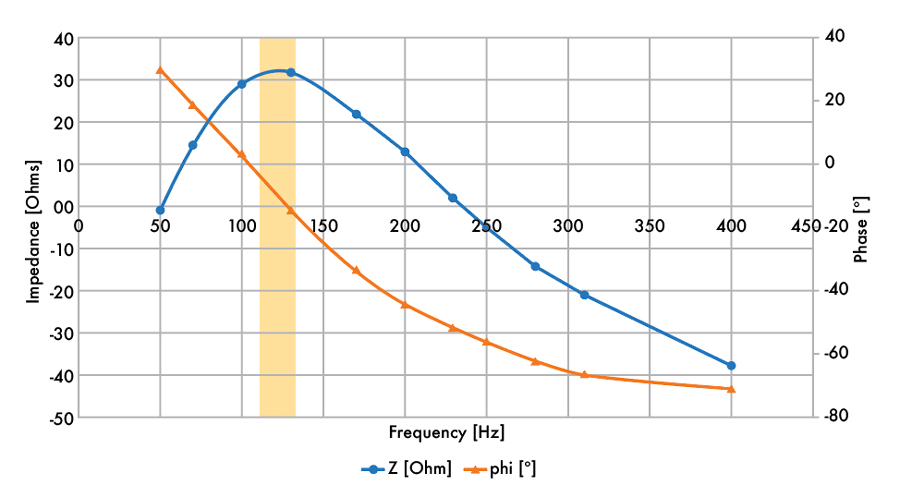
Figure 5: Test Circuit Impedance vs. Frequency
In rare cases, the required power can still be too high for a conventional power outlet. In these cases, additional low-voltage capacitors can be used to compensate for part of the reactive power needed to energize the winding. Practical experience has shown that 10–100 uF are enough. Since these capacitors are installed on the low-voltage side of the transformer (typically 600–690 V), commercial availability is usually not an issue. Figure 6 shows an example of the test setup used for onsite testing with low-voltage capacitors for reactive power compensation.
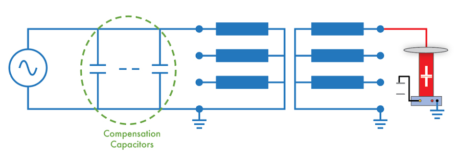
Figure 6: Voltage Source with Capacitive Compensation, Test Object, and Coupling Capacitor
ONSITE INTERFERENCE
Partial discharge measurements outside of Faraday cages are most often troublesome due to electromagnetic interference from the surroundings. For example, PD in cast-resin insulation will sooner or later lead to severe problems, as these types of insulation are not self-healing. PD will erode the insulation over time, and the dielectric strength will decrease more and more. Thus, very small levels of PD must be found and clearly identified. External interferences are often far higher than the PD signals to be detected. To overcome these challenges, modern fully digital PD instruments employ several denoising methods that can reduce or even eliminate such noise problems. A great advantage of digital compared to analog filters is their flexibility to adapt bandwidth and mid-band frequency to the actual measuring conditions. While the strict boundary conditions of IEC 60270 apply for measurement in the factory, this standard is not intended to be used on-site, even though it is recommended practice to apply its rules if possible.
As the aim of on-site PD testing typically is risk assessment, the steps to achieving the goal include reliable detection of harmful PD, identification of PD type, and location of the PD spot(s) if necessary. Evaluation of the pC-value describing the intensity is of less importance, especially if assets with non-self-healing insulation are to be investigated. Therefore, it is common for practical reasons to set the digital measuring filters of the PD instrument to frequency ranges with a lower background-noise floor. Variation of the filter bandwidth can also help to achieve a better signal-to-noise ratio (SNR).
Another powerful method is to utilize multi-band measurement filters, often referred to as the 3-center frequency relation diagram (3FREQ or 3CFRD) method. This requires three PD bandpass filters measuring every PD event simultaneously at their predefined mid-band frequencies. The synchronous consideration of three different frequency parts of the spectrum of each single PD pulse provides information on its discharge nature, signal propagation, and path attenuation. A comprehensive investigation of the spectral behavior of different types of pulses is given in reference. Selection of these three bandpass positions in the frequency domain is the key to gaining optimum benefit. By applying 3CFRD, it is possible to discriminate between pulses of different type or same type but different origin.
Figure 7 shows a simplified theoretical schematic of the principles behind 3CFRD. The red arrows indicate the response of PD pulse #1 at the discrete filter frequencies. These response values are represented by the star-shaped 3CFRD diagram as shown on the right side of Figure 7. The lengths of the phasors represent the measured response magnitudes, and the axes indicate the respective filter frequency. By adding the phasors of the PD responses, one single dot is the final representation of the initial triplet. Figure 7 shows an example of a measurement where 3CFRD was applied to separate different types of PD.
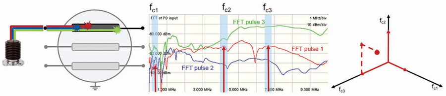
Figure 7: Simplified Theoretical Schematic of 3CFRD
PROOF OF CONCEPT
Like any innovative solution, the concept had to be proven first. Therefore, measurements took place in collaboration with manufacturers of cast-resin transformers and with wind turbine manufacturers. Figure 8 shows an initial test that was performed on a 6 MVA wind farm transformer in the factory, along with its corresponding installed location in the wind turbine.
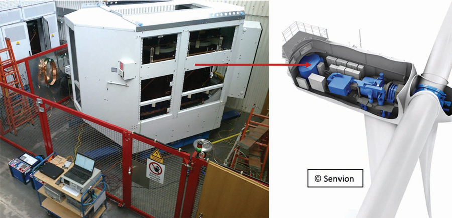
Figure 8: Test Setup in the Factory and Installed Position in the Nacelle
A pre-stress voltage of 52 kV was induced for 30 seconds, followed by three minutes at 42 kV where PD was measured. No PD activity was detected during the test.
To test the applicability of onsite induced voltage testing with PD measurements once the transformer is installed in the nacelle, a test was successfully conducted on a preparation site of a large, offshore windfarm. Figure 9 shows the test setup.
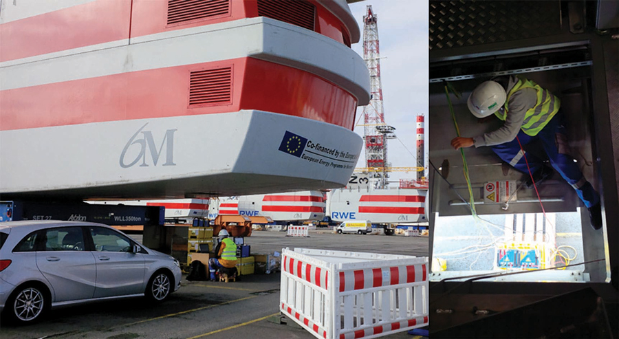
Figure 9: On-Site PD Measurements during Induced Testing of an Installed Transformer
CASE STUDIES
In recent years, several measurements have been performed using this innovative testing solution. It has also been applied outside wind farms at other applications including transformers used for the excitation of hydro-generators and transformers installed in constricted space conditions inside industrial facilities or on ships.
Case Study #1: 34.5 kV Transformer with Known PD Activity in a Wind Turbine
A 34.5 kV wind turbine transformer known to have PD activity was tested at 40 kV, and several PD sources were able to be identified. Figure 10 shows the transformer during the test and its regular position in the wind turbine. In this case, it is obvious that a small, portable test set was a necessity.
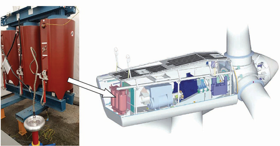
Figure 10: PD Measurement on a Transformer (left) and Position in a Wind Turbine (right)
Figure 11 shows the initial phase-resolved partial discharge (PRPD) diagram on the left and its corresponding 3CFRD diagram on the right.
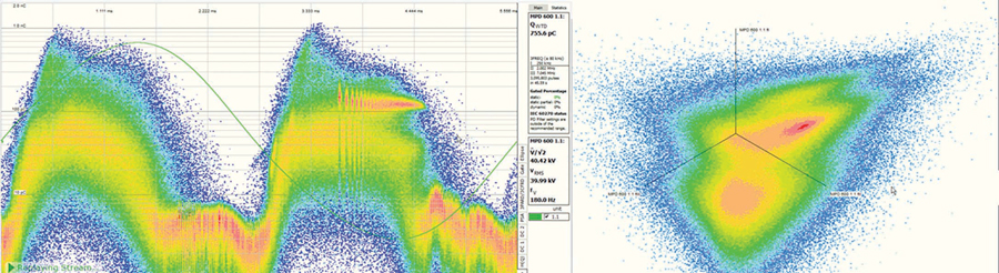
Figure 11: PRPD Pattern of the Three Filters (left); 3CFRD Measurement (right)
Figure 12 shows the individual PRPD diagrams from each selected cluster of the 3CFRD diagram. The top PRPD diagram shows contact-related PD activity; the other two PRPD diagrams show signs of internal and surface discharges. The transformers had visible signs of carbonized tracks, which indicates PD activity sustained over some time.
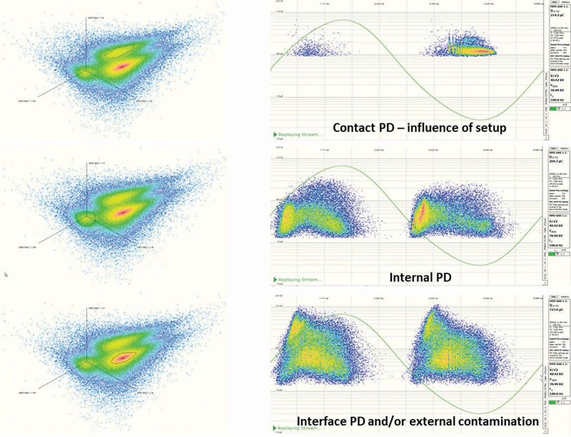
Figure 12: 3CFRD with Cluster Selected (left); Corresponding PRPD Diagram (right)
Case Study #2: Commissioning a Hydro-Generating Station
Following the commissioning of a remote hydroelectric power plant, PD measurements were requested after two of eight 10 MVA transformers, installed to excite the 400 MVA asynchronous generators, had failed. The goal of the measurements was to assess the insulation of the remaining six transformers. The transformers’ rated voltage was 19 kV on the high side and 3.9 kV on the low side. For this reason, an additional step-up transformer was needed. Figure 13 is an aerial photo of the remote generating station and a photo of the test setup.
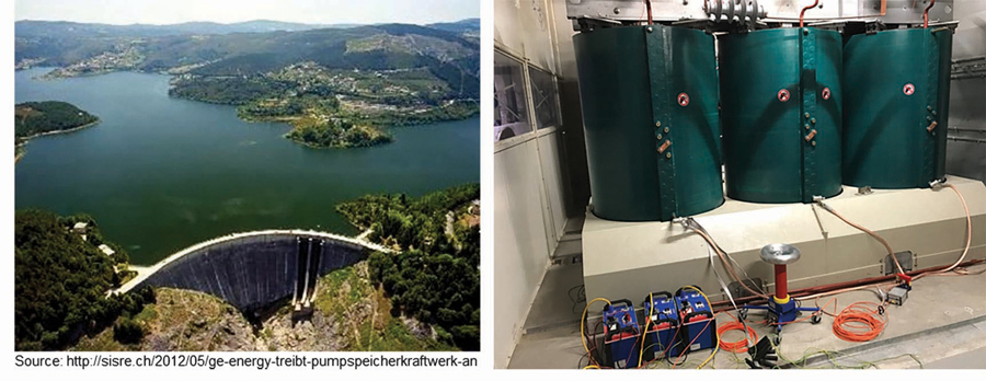
Figure 13: Aerial Photo of the GS (left); MVA Transformer under Test (right)
For these measurements, an equivalent of the factory test was required and therefore had to be done according to IEC 60270. This led to higher background noise due to external signals from nearby power electronics that could not be switched off. Using an advanced, fully digital PD instrument and the 3CFRQ cluster separation method, it was possible to confirm that no internal PD was present with a sensitivity of less than 30 pC, which was considered acceptable under the given circumstances. All transformers passed the test successfully.
Case Study #3: Diagnostic Measurement in a Data Center
Partial discharges were detected by an online PD monitoring system for a length of medium-voltage cable in an important data center. An offline PD measurement showed clearly that the cables were PD-free. A connected 2 MVA/20 kV transformer was identified as the possible source of the detected PD signals. A subsequent induced voltage test provided clear indication of the presence of void-type discharges within the solid insulation. The inception and extinction voltages were both below the transformer’s rated voltage; therefore, the risk of failure was considered high. As all phases were affected, replacing the windings was not economically justifiable; thus, the transformer had to be replaced. Figure 14 shows the test setup and the measured PRPD diagram depicting void-type discharges.
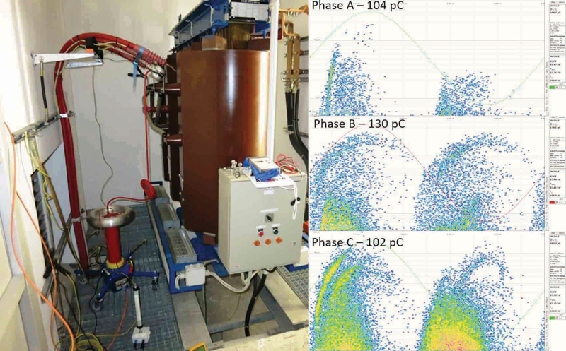
Figure 14: Test Setup (left); PRPD Diagram for all Three Phases (right)
CONCLUSION
Modern test equipment opens all kinds of new testing possibilities. Historically, onsite PD measurements for medium-voltage transformers have been difficult to perform. With the latest advancements in technology, use of a flexible and portable voltage source for PD testing combined with fully digital PD measurement technology opens new onsite testing possibilities. This results in increased reliability for modern power generation and industrial facility operators in addition to creating new business opportunities for service providers.
REFERENCES
IEEE Std. C57.12.91-2020, IEEE Standard Test Code for Dry-Type Distribution and Power Transformers, (Revision of IEEE Std C57.12.91-2011).
IEC 60076-11, Power transformers – Part 11: Dry-type transformers, International Electrotechnical Commission, Geneva 2004.
IEEE Std. C57.124, IEEE Recommended Practice for the Detection of Partial Discharge and the Measurement of Apparent Charge in Dry-Type Transformers, 1991.
IEC 60270, High-Voltage Test Techniques – Partial Discharge Measurements” International Electrotechnical Commission, Geneva 2015.
A. Kraetge, K. Rethmeier, M. Krueger, P. Winter. “Advanced noise suppression during PD measurements by real-time pulse waveform analysis of PD pulses and pulse-shaped disturbances,” IEEE ISEI, San Diego, 2010
A. Kraetge, C. Engelen, W. Guo, M. Kruger. “Field-Testing of Cast-Resin Transformers in Wind Farms, industrial and Marine Applications under Constructed Space Conditions,” Proceedings of TechCon Aus-NZ, Sydney, Australia, 2018.
 Mathieu Lachance joined OMICRON electronics Canada Corp. in 2019 and presently holds the position of Regional Application Specialist for rotating machines and partial discharges. Matthieu previously worked as a test engineer in the fields of partial discharges and high voltage. He received a BS in electrical engineering from Université Laval in 2014.
 Dr. Alexander Kraetge is a transformer expert and key account manager for the transformer industry with OMICRON electronics in Germany. After working as a professional electrician, he studied high-voltage engineering at the Berlin University of Technology and earned a PhD in transformer condition assessment. Alexander has held several technical and senior management positions within OMICRON, Austria, and Highvolt, Germany. He is an IEEE Senior Member, a member of the IEEE Transformers Committee, and is actively involved in Cigré D1 and A2. He has authored more than 100 technical and scientific publications, mainly about condition assessment of transformers and partial discharge diagnostics.