

Partial discharge (PD) measurement has been used for several decades to assess the condition of high-voltage (HV) and medium-voltage (MV) electrical apparatus. In the past, PD measurements were largely limited to the production stages of various assets (e.g., during R&D, factory-type tests, and factory acceptance tests). However, the advantages of such testing have resulted in it being used more often during onsite commissioning, periodic maintenance, and monitoring.
Partial discharge is defined as a localized dielectric breakdown of a small portion of an insulating material. PD events occur when the local electric field exceeds the local dielectric strength of the insulation. When a PD event occurs, a short-duration current pulse (in the nanoseconds range) is generated. This current pulse can be measured using various types of sensors.
In many cases, PD events are detectable at the early stage of insulation deterioration. Therefore, PD measurements can provide early warning to operators and allow time to plan corrective actions when needed. For this reason, PD measurements are commonly performed on apparatus such as rotating machines, transformers, cables, instrument transformers, and switchgear. Figure 1 is a schematic of a typical PD measurement setup according to IEC 60270.
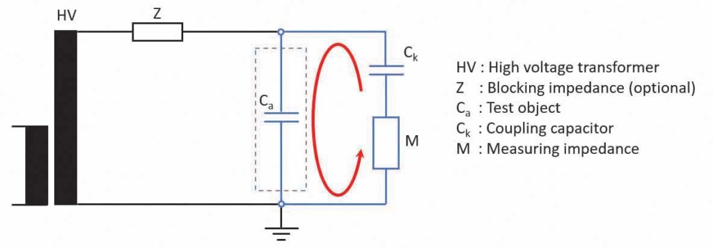
Figure 1: PD Measurement Setup According to IEC60270
This article shares a recent case study of onsite commissioning of a medium-voltage air-insulated switchgear. It exposes the benefits of PD measurement as an onsite diagnostic test and highlights the advantages of using an advanced partial discharge measuring system to enhance, facilitate, and accelerate PD data analysis.
Case Study
In April 2020, Advanced Electrical Services (AES) was contracted to perform commissioning of a newly installed 27.5 kV air-insulated switchgear (Figure 2) located in Nisku, Alberta. The commissioning was to include offline partial discharge measurements and would be performed according to ANSI/NETA standards.
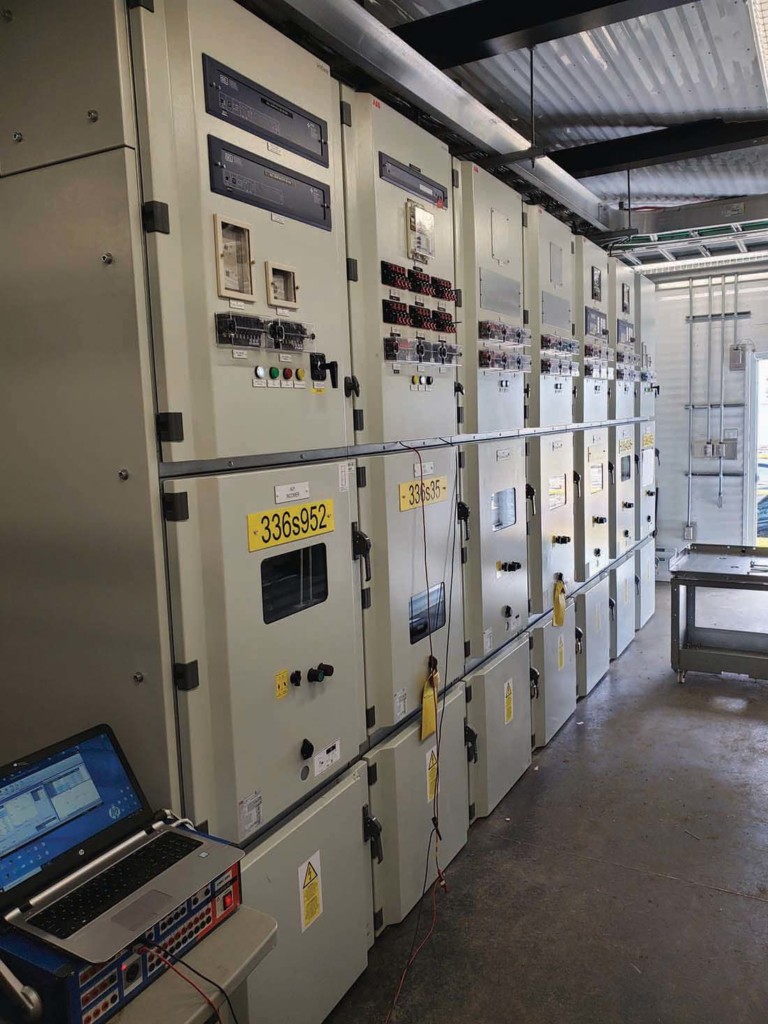
Figure 2: Air-Insulated Switchgear
To take full advantage of the advanced functions of a newly released PD measurement and analysis system, onsite support from the PD equipment manufacturer was requested. However, the COVID-19 travel and safety restrictions implemented across many Canadian provinces and regions made onsite support impossible. Therefore, after consideration, the PD measurements would take place with remote virtual support from the PD equipment manufacturer. This solution allowed the test to take place without increasing the risk of transmitting the novel virus.
A safety hazard always exists when a high-voltage source is used to energize the test object. In this case, the maximum test voltage was 30 kV AC. Since the company had experience testing medium- and high-voltage air-insulated, vacuum, and GIS switchgear, all parties felt comfortable to go ahead with remote PD measurement testing. The PD measurement and analysis system would be shipped to the site, and the test would be conducted by onsite personnel with live virtual support from the manufacturer’s application engineers.
It was important for onsite personnel to feel comfortable with the new PD equipment. Therefore, the equipment was received approximately one week prior to the scheduled testing date. This allowed the manufacturer’s application engineers to provide initial training on the new PD measurement system. In addition, a customized profile was created for that specific application, enabling the operator to visualize only the functions he would require during the test (Figure 3 and Figure 4).
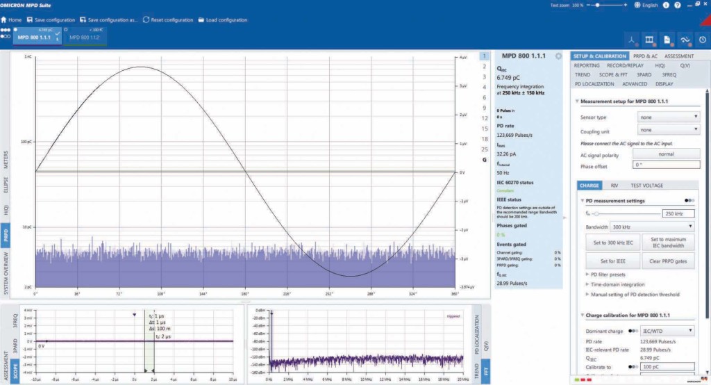
Figure 3: Default View of MPD Software
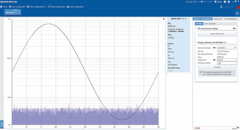
Figure 4: Customized View Used for PD Test
On the first day of onsite testing, performance and safety checks determined that partial discharges were present on one of the cables from the high-voltage source, and the cable would need to be replaced for the measurement. Once completed, the actual testing of the switchgear could begin.
Prior to the PD measurements, the switchgear had successfully passed an AC dielectric withstand test, commonly referred to as a Hipot test. However, during initial PD measurements, high PD levels were measured on all three phases at a voltage of approximately 5 kV. The remote connection to the manufacturer’s engineers allowed fast response, and analysis of the phase-resolved partial discharge (PRPD) diagram (Figure 5) determined that conductive parts were left at floating potential inside the switchgear. This meant those conductive objects were neither insulated nor grounded properly.
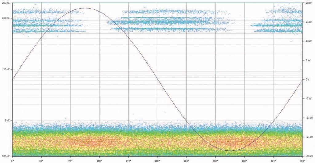
Figure 5: PRPD Patterns Indicating Objects at Floating Potential
To locate the source of the partial discharges, various areas of the switchgear were isolated and tested by opening and closing some of the breakers. This process of elimination helped narrow down the search area to the main bus compartment. Visual inspection to verify the findings of the PD measurements was initiated, and after opening and inspecting the switchgear, the team found several anomalies inside the main bus compartment. Numerous pieces of hardware used for assembly had been left uninstalled inside the switchgear along with a pair of electrical pliers. In addition, critical errors in switchgear assembly, such as unconnected corona rings (Figure 6), were discovered. These findings confirmed the initial diagnosis from the PRPD analysis.
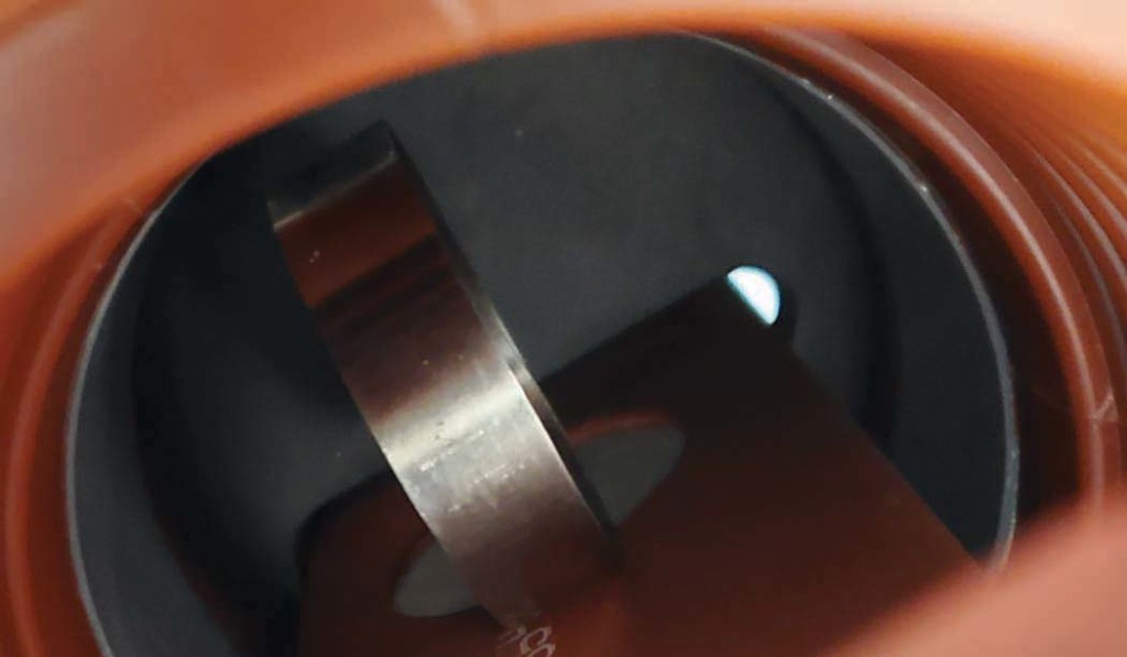
Figure 6: Corona Ring Improperly Connected
The pieces of hardware were removed, and the corona rings were connected according to the manufacturer’s specifications. PD measurements were then repeated, and all PD apparent charge levels were below 100 pC, which was the passing criteria at a voltage of 19 kV (Figure 7).
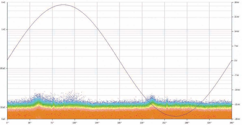
Figure 7: PRPD Pattern at 19 kV after Corrective Actions
These types of anomalies are commonly found in air-insulated switchgear after onsite assembly. Unfortunately, they are too often only detected by visual inspection several years after the original commissioning because of obvious signs of deterioration, or in the worst case, after a failure.
Conclusion
The AC dielectric withstand test is typically the only onsite insulation test performed on these assets, and it only detects major defects. Objects left behind can cause partial discharges that deteriorate the insulation over time and create an abnormal amount of ozone. This can eventually damage the equipment, lead to in-service failure with significant economic losses, or more important, pose considerable risk to the health and safety of onsite personnel.
Partial discharge measurements can be used to assess the insulation of various medium- and high-voltage apparatus. Technology advancements in recent years have made PD measurement systems more attractive for onsite testing. They provide users with a high-end and robust system, and customizable profiles allow users to optimize their testing experience based on the specific application.
Acknowledgments
The authors thank Joshua Blanchette, Stive Hailu, and Zak Houk for their on-site support during the measurements.
 Mathieu Lachance joined Omicron electronics Canada Corp. in 2019 and presently holds the position of Regional Application Specialist for rotating machines and partial discharges. Mathieu previously worked as a test engineer in the fields of partial discharges and high voltage. He received a BS in electrical engineering from Université Laval in 2014.
 Tim Gannon, a Red Seal Journeyman Electrician, is currently the Field Service Manager for Advanced Electrical Services (AES) in Edmonton, Alberta, Canada. His career spans 20 years in the electrical industry in roles relating to construction, manufacturing, and more recently, testing and commissioning.