
Measuring the winding resistance of generators and motors is one of the essential tests used in factory acceptance testing and during periodic routine testing procedures. This test can detect various problems in rotating machine windings, including a turn-to-turn short circuit in windings, which reduces a motor/generator’s ability to produce a balanced magnetic field, and a phase-to-phase short circuit, which in most cases results in a motor/generator trip, etc. The usual procedure for winding resistance measurement tests is using DC current, waiting for resistance stabilization, and recording the resistance value. The resistance value is dependent on the winding temperature; therefore, it is necessary to correct the value to the reference temperature.
Recently, manufacturers of rotating machines and test instruments have joined forces to develop a new testing method capable of detecting even small irregularities in winding integrity (weak connections) that could not be spotted using the traditional way of testing winding resistance. The new method requires a high DC test current of at least 300 A and the capability to run a continuous test to generate heat in the weak points in the generator. The measurement circuit must continuously record resistance values with very-high accuracy to detect even very-low resistance changes (in the range of a few µΩ).
This test has high value for asset owners and manufacturers of large generators with nominal currents of thousands of amperes. Even small irregularities in connections can cause significant temperature increases concentrated in a single point. Since rotating machines usually operate under high vibration and mechanical stress, small irregularities can develop into big failures.
MAINTAINING ROTARY MACHINES
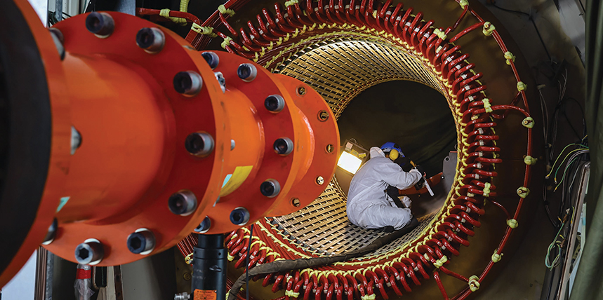
The market offers a wide range of electrical rotating machines (motors and generators). They are key components in the power generation and industrial sectors. Electrical machines operate in important applications and must be reliable since failure can introduce huge damage to the machines as well as the entire system, causing high economic losses. Generators are exposed to various negative influences during operation:
- Thermal: High and low temperatures, overload, hot spots
- Electrical: Partial discharges, surges, overvoltages
- Ambient: Contamination, humidity, particles
- Mechanical: Vibration
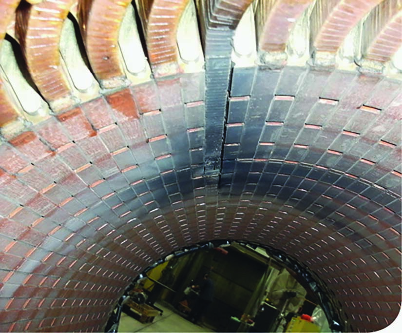
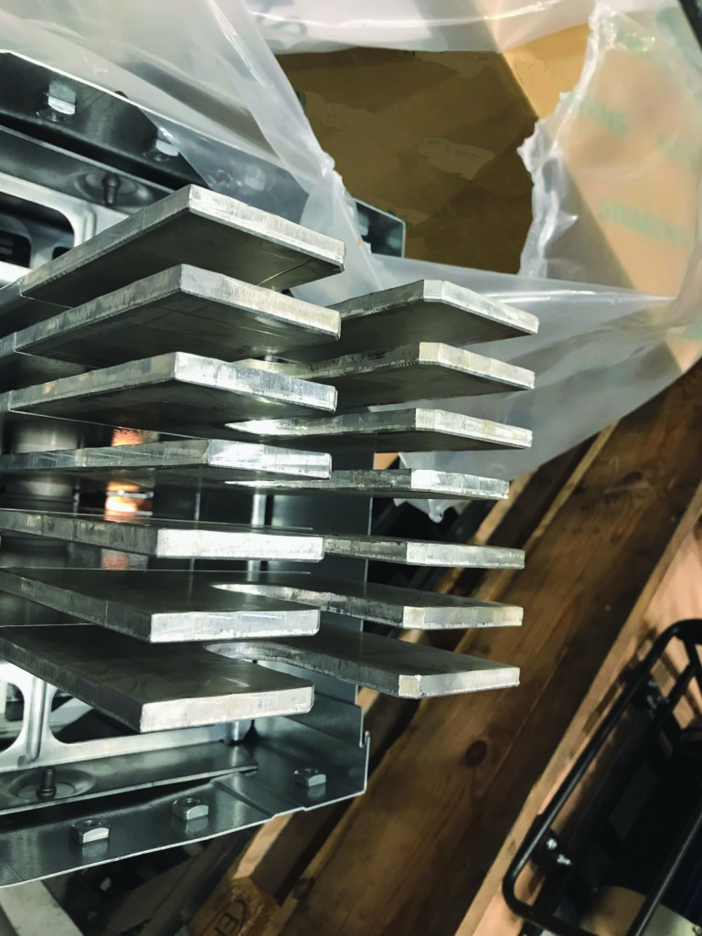
It is critically important to create a maintenance strategy that will not only find a failure but also predict possible failures (such as a missing wedge shown here) and provide an estimate of the remaining asset life span. The strategy should include a set of testing methods employed to investigate the condition of various parts of the motor by checking insulation, connections, power losses, vibrations, etc., to increase the reliability of the asset and extend reliable service life.
RELEVANT STANDARDS
Fortunately, relevant standards and guides clearly define testing procedures for rotating machines. Standards and guides are defined based on the collaborative work and experience of numerous relevant companies worldwide. It is important to mention these relevant standards:
- IEEE Std. 43-2013, IEEE Recommended Practice for Testing Insulation Resistance of Electric Machinery
- IEEE Std. 112-2017, IEEE Standard Test Procedure for Polyphase Induction Motors and Generators
- IEEE 1415-2006, IEEE Guide for Induction Machinery Maintenance Testing and Failure Analysis
Additionally, handbooks and maintenance guides created according to the relevant standards and internal experience are available from manufacturers.
TESTING METHODS
A rotary machine should be tested and inspected during each phase of its life cycle, including manufacturing and final testing, commissioning, periodical routine testing, after experiencing a faulty condition, and after repair/refurbishment. Several electrical diagnostic testing methods that allow condition assessment of various components of the rotary machine are available and recommended. Common electrical testing methods include:
- Capacitance and tan δ test
- Partial discharge (PD) test
- Voltage withstand test
- Insulation resistance test
- DC winding resistance test
- Connection resistance test
- SFRA (sweep frequency response analysis)
This article focuses on two similar tests: DC winding resistance and contact resistance.
Winding Resistance Measurement
The DC winding resistance test checks stator and rotor windings and all circuit connections. Winding resistance measurement procedures are provided in IEEE Std. 118-1978, IEEE Standard Test Code for Resistance Measurementand IEEE Std. 119-1974, IEEE Recommended Practice for General Principles of Temperature Measurement as Applied to Electrical Apparatus. The procedures should be followed when measuring the resistance of the stator winding and the rotor winding on wound-rotor machines. The test results are also used to calculate power losses in stator windings (I2R).
Connection Resistance Measurement
The contact resistance measurement test focuses only on checking individual contacts. Contact resistance is usually very low, from a few to tens of microOhms. Accurate and reliable measurement requires a higher test current to create a higher voltage drop (measured signal). During the manufacturing process in the factory, the connection resistance test is important to verify that all wires, windings, and leads are connected properly, which means tight contact with good pressure without the possibility of moving and shaking. Insufficient contact will cause higher resistance, which will be followed by higher power losses in the form of heating. Heating is concentrated in the weak point (connection) and can create a larger problem in the form of damage to windings or insulation.
A DC voltage instrument is used to measure winding resistance R. The test cables should be connected to the outputs of the machine, and the resistance will be measured between those points. DC and DC voltage are measured simultaneously for each phase, and the resistance is calculated simply as:
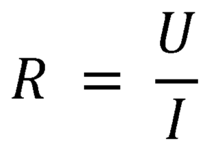
However, motors and generators are inductive loads, and the stator and rotor windings have inductance L and capacitance C in addition to resistance R. This means the reach of the test current should be slightly longer than in the case of a purely resistive shunt. At the beginning of the measurement, it is common to see a slightly different resistance value than expected, but this will stabilize on the expected value after a certain period defined by the time constant of the RLC circuit.
When the test is finished, some of the inductive or capacitive energy remains in the circuit. The test device must have a safe discharging circuit capable of discharging remaining energy after the winding resistance test has been completed.
Four-Wire Testing Method
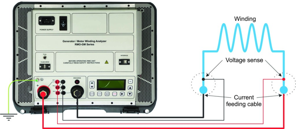
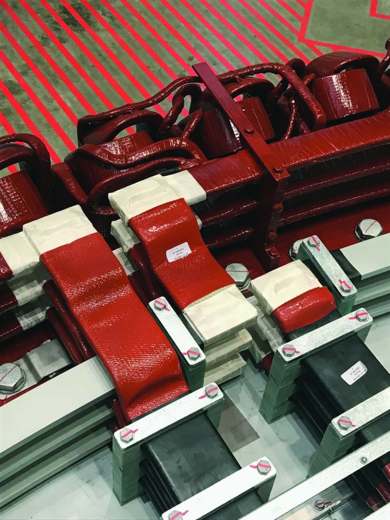
The winding resistance test is usually performed by using a four-wire measurement approach. This enables the most reliable test results and minimizes the influence of the test setup because it ensures that the resistance of the connecting current cables is not included in the measurement.
The test current is passed through the windings using high-current cables. The voltage drop across the windings is measured using sensing cables. The placing of the cables is very important. The current cables should always be placed outside of the sensing cables. That way, the resistance of cables and clamps is almost completely excluded from the resistance measurement (Figure 1).
Resistance Temperature Compensation
Generator windings are made from materials (usually Cu) whose resistance is dependent on temperature. Since the winding resistance test is a comparative method, the resistance values must be temperature corrected to a reference temperature to compare the results. Resistance correction for temperature is performed according to the following equation from IEEE Std. 112-2017[3]:
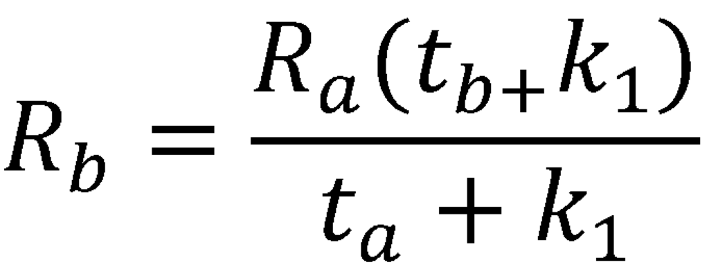
Where:
Rais the measured winding resistance value at temperature ta
tais the temperature in ˚C of winding when the resistance Ra was measured
tb is the reference temperature for resistance compensation
Rb is the measured winding resistance value corrected to the temperature tb
k1is the specific temperature coefficient for the winding material (e.g., 234.5 for copper or 225 for aluminum)
The test device’s temperature channel enables the temperature value to be measured whenever the resistance value is recorded. Additional temperature sensors can be used to increase temperature measurement accuracy. The average temperature of all measured sensors should be used when the resistance was the measured winding temperature at the moment of the resistance measurement. This is to compensate for the resistance value to a reference temperature.
NEW TESTING APPROACH
The proposed testing method’s main goal is to detect small contact irregularities in the windings of large generators with high nominal current where even a small irregularity in windings, connections, or joints has the potential to create a huge problem. Any contact irregularity will increase resistance.
Power losses through heating are proportional to the square of the current (P = RI²). In the case of generators with high nominal current, even small changes in resistance will create significant heating concentrated at that point. To get a better feeling for a potential issue, 10 microOhms of increased resistance with a nominal current of 8,000 A results in additional heating of 640 W at that point.
The new test could have a huge benefit in the factory to verify that everything is connected properly before transporting the generator to the customer site. It would also be useful to perform this test during commissioning to determine whether transportation and installation have caused any connection issues.
The method to detect changes is to inject a high current through generator windings — high enough to initiate heating on weak points. The initiated heating should influence resistance, which can be detected by measuring the device while continuously recording resistance values. It is also important for the test current to flow continually for a certain period. During that measuring period, the winding resistance will be recorded periodically (e.g., every second). Based on numerous experimental tests on large wind turbine generators, a test duration of 60 seconds and a sampling time of 1 second are proposed.
The test device should be powerful enough to run a high test current through the generator windings for a longer period. The electrical circuit contains cable resistance and winding resistance. The test device (Figure 2), specially designed for this application, can provide a test current of 300 A DC for a period of 600 seconds (a lower test current can run for an unlimited time) and can measure the winding resistance of the majority of large generators with a winding resistance up to approximately 30 mOhms.

Since the goal is to detect even small changes in resistance (range of µΩ-s), the test device should have high accuracy. The device used for this test has a typical accuracy of ± (0.1% rdg + 0.1% FS) and resolution of 0.1 µΩ for the range 0 µΩ–999.9 µΩ and 1 µΩ for the range 1,000 mΩ–9.999 mΩ, where rdg is reading and FS isfull-scale value. IEEE Std. 112-2017 requires the test device to have a valid calibration certificate within 12 months and minimum accuracy of ±0.2% of the full scale.
When inspecting test results, winding resistance and behavior resistance in the test period should be analyzed (Figure 3). Based on experimental tests, it was concluded that 60 seconds is enough time to catch the stable value of the resistance. This period is also long enough to show the change in resistance if some irregularity is presented.
If unexpected resistance value and resistance behavior during the measurement period is detected and confirmed, additional testing and inspection should be performed. This includes visual inspection of each connection and joint in the windings and measuring connection resistance directly on the connections using a high test current of 300 A DC. A good connection between connections and test leads must be confirmed.
TEST RESULT INTERPRETATION AND ANALYSIS
When the winding resistance test is performed, the test results should generally be compared with the reference results between different phases or with the sister unit. A variation indicates a potential connection problem or winding damage. In some testing methods, it is important to focus not only on the value of the behavior of test results but also on a predefined period.
CASE STUDY
The tested generator is a wind turbine direct-drive generator with permanent magnets. The continuous nominal power is 11 MW. The generator has two systems, each with 3 phases, connected to a converter. The converters control the generator and the grid feed (usually it is between 20 kV and 66 kV).
Because of the high nominal current, the tested generator’s two cable systems must be tested separately. Test results between the three phases for both systems are presented in Figure 4 through Figure 9.
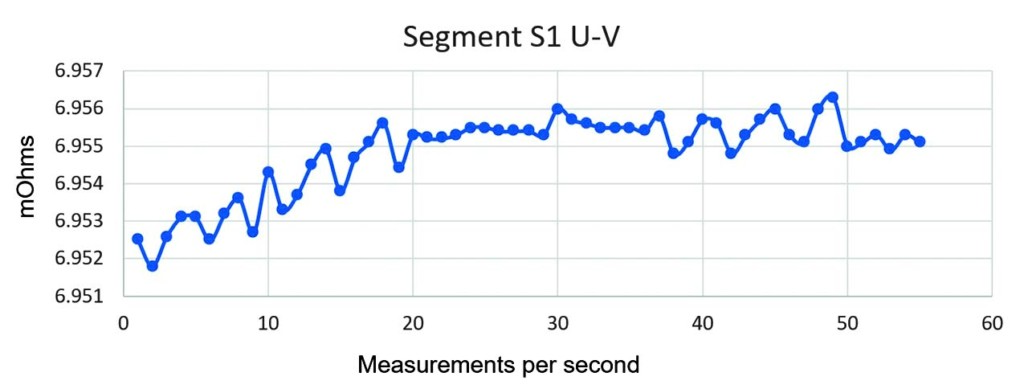
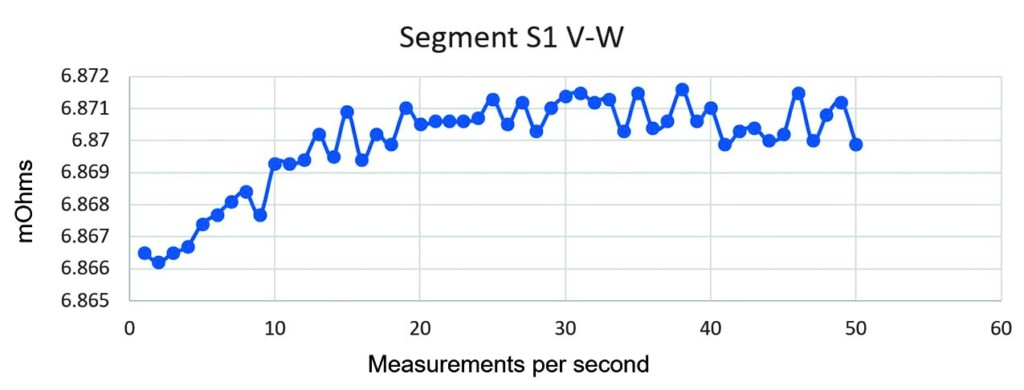
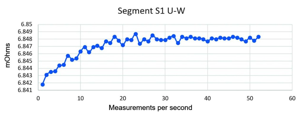
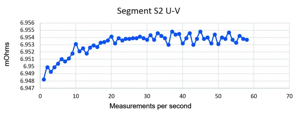
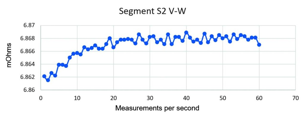
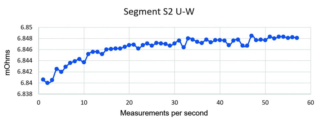
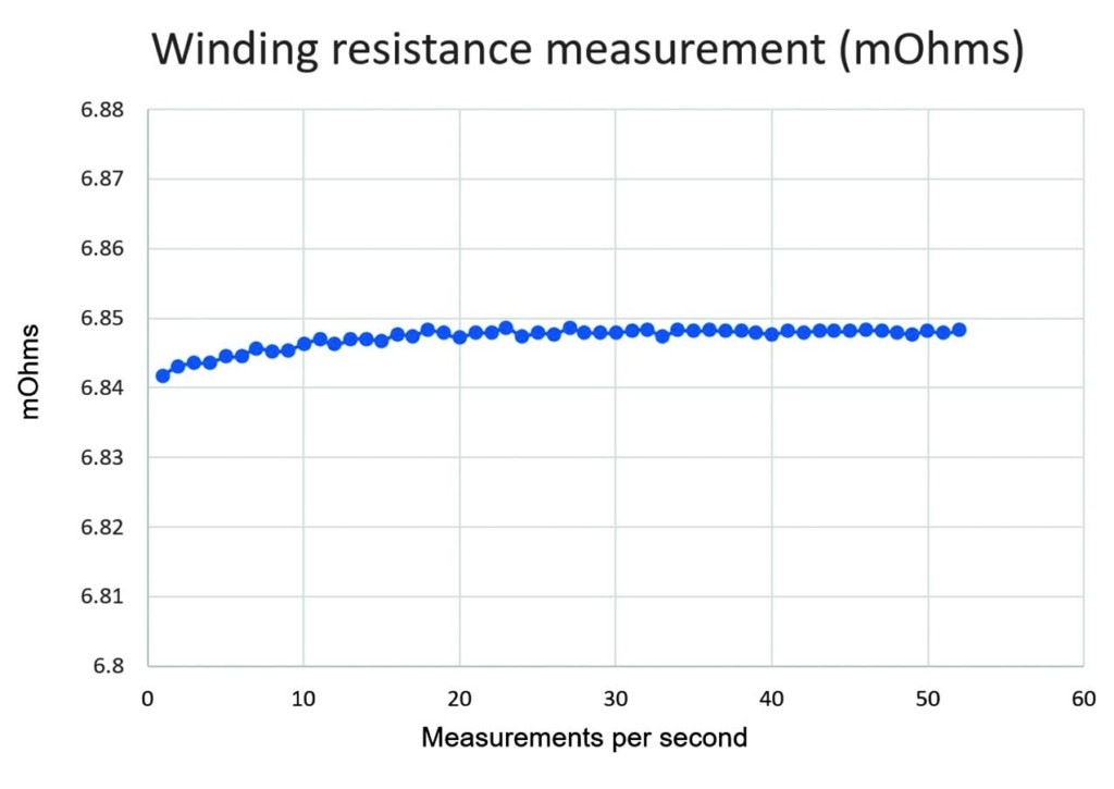
Figure 10 shows the typical winding resistance graph for the tested wind turbine generators.
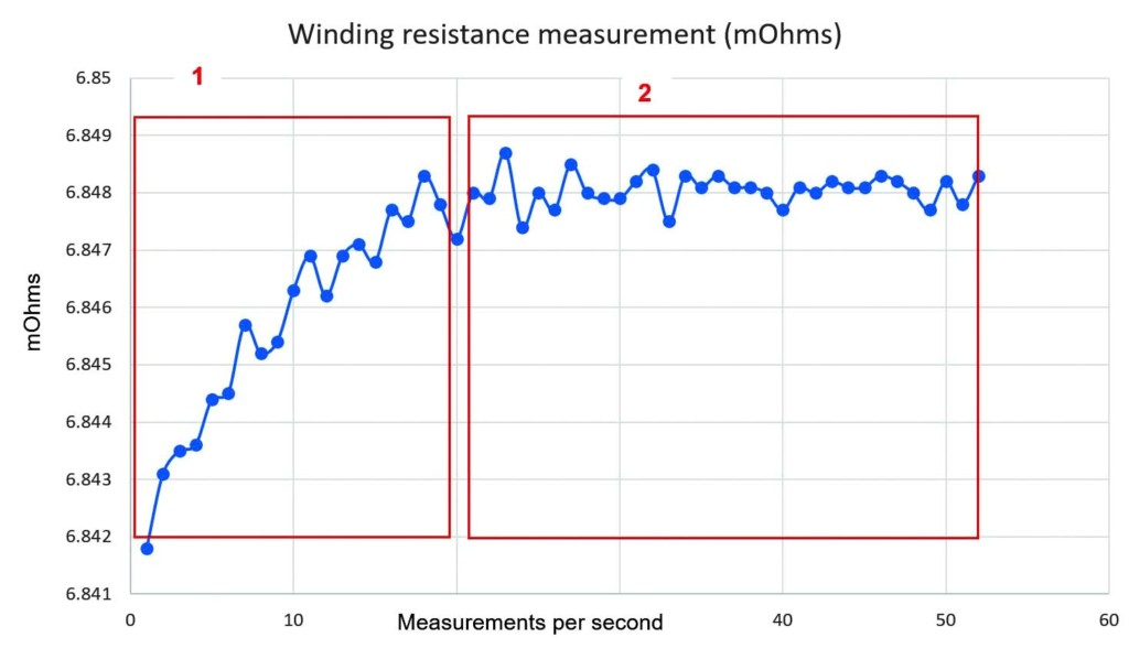
Note: The graph is zoomed in, and the total resistance change is quite small — approximately 6 µΩ. However, two zones can be detected on the graph:
- The first zone is the stabilization process. In this case (big generator with a permanent magnet instead of the rotor windings), the dominant component is capacitance, not inductance. The generator has high capacitance, which charges over time and causes the stabilization process defined by the time constant RC. High cross-section windings with a lot of insulating materials and large surface connections all cause high capacitance between components and components to ground.
- The second zone is where the dominant component in the circuit is resistance R, which is the focus of interest. Changes in resistance value in this graph are most likely caused by heating. Small changes between samples (0.5 µΩ) are not of interest, as they are caused by the imperfection of the real test device. We are interested in the tendency for the resistance value to change if the slope of the graph in the second zone increases.
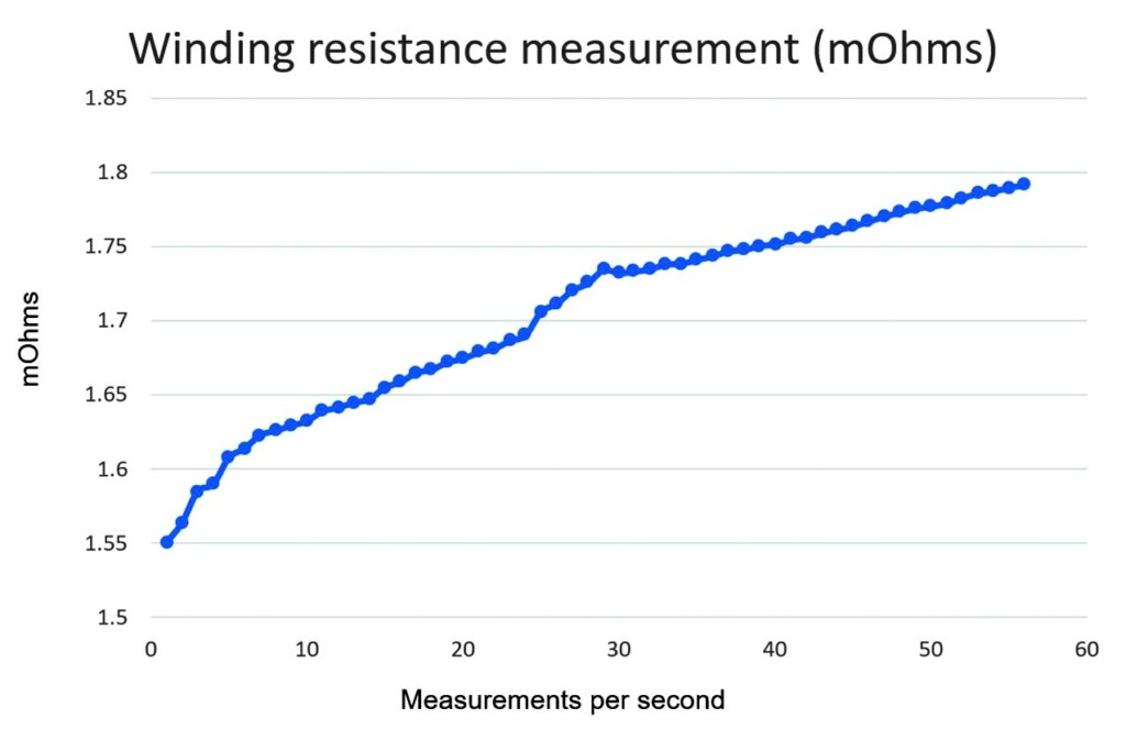
An example of changing resistance caused by heating is presented in Figure 11. The trend of changing (increasing) resistance is noticeable even in the second part of the graph.
CONCLUSION
Understanding how large and expensive problems can appear in the case of a generator or motor failure will determine the various inspection and maintenance strategies. For example, the reliability of generators used in power generation is crucial, so the maintenance strategy is quite strict and is continuously being improved by using new testing methods and online monitoring.
The proposed test method provides benefits in various stages of a generator’s lifecycle. The method can be used to verify the manufacturing process and eliminate possible manufacturing imperfections. The test will provide information about the winding resistance value as well as the tendency for the value to change. Questionable results could initiate an additional inspection of all connections and joints in the generator windings.
The test can be useful during commissioning testing to verify whether transporting the generator caused any damage to the joints and connections of the winding. Since the wind turbine generator operates in a demanding environment due to weather, vibration, mechanical stress, etc., it could be useful to periodically perform the routine procedure.
Since the method is new, failures and experiences collected over time could bring some modifications to the method. One potential improvement is to use a higher test current. Higher test current has the potential to generate more heating in weak points of generator windings that would cause changes in resistance. However, the nominal generator current should be considered as well, and the test current should not be too high; otherwise, it can heat a complete winding and increase resistance. This would require a more complex analysis. For operators who follow ANSI/IEEE standards, the maximum test current should not be higher than 15% of the nominal current. For those who follow IEC, the maximum test current should be 10% of the nominal current.
REFERENCES
[1] Penrose, Howard W. “Why Wind Generators Die Young and How to Make Them Work Longer.” Windpower Engineering. Accessed at www.windpowerengineering.com/why-wind-generators-die-young-and-how-to-make-them-work-longer/. [2] DV Power. DV Power Manual RMO-GM — M-RXX0MN-307-E. May 2019. Accessed at www.dv-power.com/download/rmo-a-series-user-manual/. [3] IEEE Std. 112-2017, IEEE Standard Test Procedure for Polyphase Induction Motors and Generators. [4] IEEE Std. 43-2013, IEEE Recommended Practice for Testing Insulation Resistance of Electric Machinery. [5] IEEE 1415-2006, IEEE Guide for Induction Machinery Maintenance Testing and Failure Analysis.
Edis Osmanbasic is an Application and Testing Specialist at DV Power, Sweden. His work involves the analysis and development of test methods for condition assessment of transformers, OLTCs, and generators. He is responsible for DV Power transformer test equipment field application and diagnostics of transformer test results and is also involved in defining and proposing the maintenance strategy for the HV equipment. Edis has published numerous papers on DRM methodology and transformer testing methods. He holds an MS in electrical engineering from the University of Sarajevo.

Normen Kaemena is an Electrical Engineer for test benches and production support at Siemens Gamesa Renewable Energy GmbH. He is responsible for testing methods, laboratory test development, production support, and production process optimization. He is also involved in creating maintenance plans and maintenance strategies. He specializes in partial discharge measurement.