
Conventional testing of medium- and high-voltage circuit breakers (MV/HV CBs) involves measuring the timing and travel of the main contacts and their corresponding resistors (pre- or post-insertion) if any, along with the current profile of the operating coils, and occasionally the timing of auxiliary contacts.
This article explains several techniques available to improve or extend the scope of testing. Aspects reviewed include improving the safety and efficiency of conventional practices, testing circuit breakers that are normally not tested due to the difficulty they present, and using additional or alternative testing techniques to assess specific circuit breaker components.
Circuit breaker analyzers (CBAs) are versatile instruments that can be used to extend testing capabilities beyond conventional testing to achieve better or focused assessment of circuit breakers depending on their application or criticality — all by simply adding accessories. This article provides insight into techniques that can be implemented and the advantages of adding them to a maintenance plan.
CONVENTIONAL CB TESTING
MV/HV CBs are installed in systems above 1 kV with various insulating media: air magnetic blast, vacuum, oil (low and bulk volume), SF6, or new insulating gases developed by CB manufacturers. Vacuum is the most common for MV CBs and SF6 for HV CBs. The mechanism that drives operation of the breaker is commonly spring-based, but pneumatics and hydraulics are also used. Magnetic mechanisms are currently common on MV vacuum CBs. Depending on size and application, the breaker may have one or three mechanisms:
- One single mechanism for the three phases, commonly known as three-pole operated
- One mechanism per phase, known as single pole or independent pole operated (IPO)
A circuit breaker isolates the source from the load when it is in open position as well as any side from ground under any circumstance. Insulation tests, such as insulation resistance, power factor, vacuum bottle integrity, or gas analysis, are required to assess the condition of the insulation.
When the breaker is closed, it should provide continuity to the circuit with extremely low impedance to avoid losses and consequent heat that deteriorates the contacts and can cause catastrophic failure of the breaker. A contact resistance test is used to determine whether the contacts are within specs. High values from the reference or elevated differences between the contacts are indication of wear, contamination, or looseness of the contacts.
The third main function of a circuit breaker is to act as a switch for operational maneuvers or protection against faults in the system. MV and HV circuit breakers rely on external commands to operate under protection conditions. External commands are applied to a control circuit, which in turn uses coils and contacts to actuate the mechanical or electrical restrain to release the energy stored in the mechanism to close or open the breaker. The breaker should also be capable of opening correctly immediately after closing in cases where the breaker is closed under an existing fault; this function is called close-open or trip-free. In other instances depending on the system and the type of breaker, the breaker should be able to open and close after a certain delay to act as a recloser. If the fault persists, the breaker should open again immediately. These operations are called open-close and open-close-open.
All of these operating characteristics are included in manufacturer specifications and should be within certain timing and travel parameters. They can therefore be verified with a test that simulates the external commands to the control coils, measures the operating times of main and resistive contacts, calculates synchronism of the poles, and characterizes mechanical behavior by plotting the travel curve and calculating the speed, acceleration, rebounds, stroke, and penetration, among others. This comprehensive test, called timing and travel analysis, is performed with a circuit breaker analyzer (CBA) and the appropriate transducers.
CIRCUIT BREAKER ANALYZER
In a very simplified description, a CBA is a test instrument that simulates the operating pulses from relay and control systems by closing a contact in a control module to initiate a timer and operation of the breaker. Simultaneously, another set of modules or channels are activated to measure different parameters. These modules operate with analog or digital signals.
One module is dedicated to simulating the operating signals. Other modules are dedicated to measure:
- Timing of the main contacts by applying voltage to each pole and detecting the make- or-break by measuring current circulation or interruption, in essence a continuity measurement. Resistor contacts (pre- and post-insertion) timing is measured the same way and includes measurement of the resistance.
- Timing of auxiliary contacts using a similar concept of continuity measurement.
- Travel of the breaker mechanisms through analog or digital channels and the usage of the corresponding transducers mechanically attached to a specific point of the circuit breaker drive. The module measures the analog or digital signals for the entire operating period and converts the information to travel parameters (length, angle, speed) using manufacturer conversion factors or tables. Results are displayed numerically and graphically to show the behavior of the mechanism throughout the entire operating time.
The analog channels of a CBA can be used to measure signals from various accessories. This allows the instrument to be used for the following tests, thus expanding the usage of a CBA as a comprehensive and efficient tool.
Dual Ground Testing
The conventional timing method requires the breaker to be isolated from ground at least from one side. Even though the circuit breaker under test is isolated from high voltages and grounded on one side, three main possibilities still exist for the breaker to become energized to a dangerous high potential:
- Accidental energization of the line from some unwanted source of potential
- A lightning strike on the lines or bus connected to the circuit breaker
- Most common, capacitive coupling from another conductor that is energized. The voltage from capacitive coupling can sometimes generate 20 mA or more of current that can be pushed through a human body.
To minimize the safety hazard, the common practice is to ground both ends and only remove one of the grounds for the testing operations. When the timing equipment is connected to the circuit breaker under test, it provides a direct path to the technician for this capacitive-coupled current. Timing equipment should always be grounded while testing in a substation, but the induced current will still flow through the equipment to ground as seen in Figure 1.
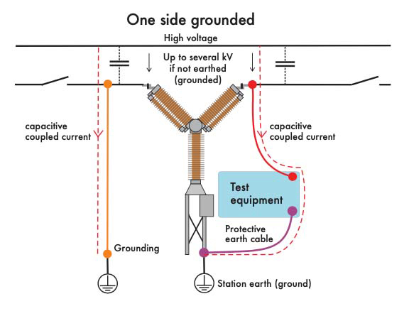
Figure 1: CB with One Side Grounded for Testing
If the ground fails or the technician inadvertently removes one of the timing leads from equipment, the technician is now the easiest path to ground, and the induced current will flow through the technician. When the circuit breaker is grounded on both sides as in Figure 2, the induced current flows directly to ground and not through the test equipment or test technician.
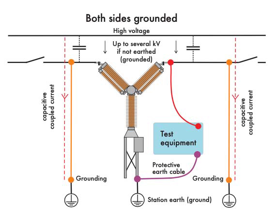
Figure 2: CB with Both Sides Grounded for Testing
The added step of disconnecting the ground to test and reconnecting it to complete the setup and return the CB to service adds extra time to the procedure, which can represent one or two extra hours to complete the testing depending on the size of the breaker and internal company practices. Additionally, safety is compromised as was shown in Figure 1 while the tests are conducted. Some international standards, including IEC EN 50110-1, require working on components in high-voltage environments only when both sides are grounded.
CBA analyzer manufacturers have implemented techniques to be able to time breakers with both ends grounded, and utilities are gradually implementing them in their procedures due to the benefits of increased safety and reduced outage time.
DCM Testing
One leading technique uses dynamic capacitance measurement (DCM), which relies on the natural capacitance of the circuit breaker to distinguish between closed and open states. A simple representation of a circuit breaker (Figure 3) consists of a moving contact and a stationary contact separated by some type of insulating medium, commonly vacuum, oil, or SF6 gas, i.e. the circuit breaker is a capacitor.
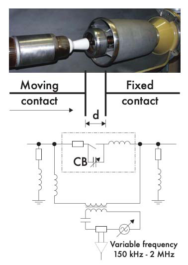
Figure 3: RLC Model of a Circuit Breaker and DCM Test Setup
By placing a variable frequency generator in parallel with the circuit breaker, an LRC circuit is formed. The inductance and resistance is composed mainly of the leads connecting the frequency generator to the circuit breaker and the ground leads; the capacitance is from the circuit breaker itself.
Measuring the dynamic capacitance allows the maximum capacitance value for each contact to be determined. This happens when the contacts have the minimal separation before the make of the contacts. The moment of this maximum capacitance is used to start and/or stop the timer to measure the breaker operating times.
Figure 4 includes two graphs of current vs. frequency — each with its own resonance point. When the circuit breaker is in the closed position, frequency varies between 150 kHz to 2 MHz to establish a minimum current response, at which point the frequency is locked into this position. When the circuit breaker is operated, the test current is continuously monitored at a high frequency (typically 40 kHz). When the contacts first separate upon opening, or right before they first touch on closing, the capacitance in the circuit is at maximum, and the resonance point shifts from the established minimum recorded while the circuit breaker was closed. As stated previously, if a timer records from close or trip coil energization to this shift in current response, accurate contact times per IEEE Std. C37.09 and IEC Std 62271-100 are recorded.
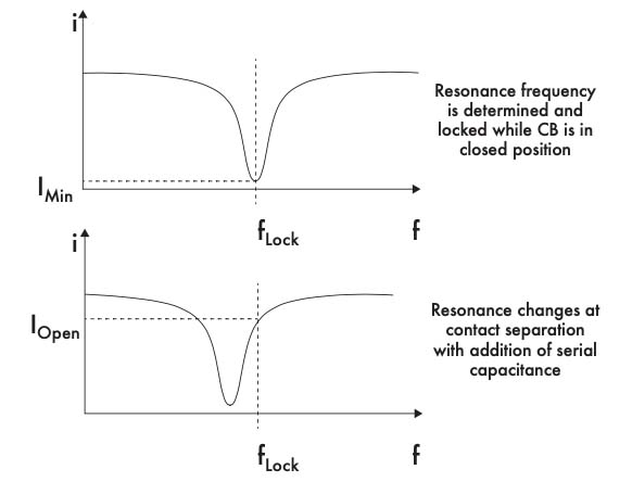
Figure 4: Current vs. Frequency for Contacts Closed and Contact Separation
A CBA with the ability to operate with a DCM accessory allows a breaker to be tested more safely and efficiently, totally immune to 50/60 Hz interference, and with the added advantage of displaying the results in the conventional timing format.
Dynamic Resistance Measurement (DRM)
This testing technique monitors contact resistance by circulating a DC current and measuring the voltage drop across the contacts of the breaker while it is opened or closed. The purpose is to plot the resistance rather than obtaining a specific contact resistance magnitude. This plot depicts the condition of the surfaces of the contacts and the various sections along the travel of the moving contact over the fixed contact.
The typical DRM response of the open operation of a breaker with arcing contacts (Figure 5) shows a flat line during the first milliseconds, then a slight increase in resistance as the moving contact begins to travel towards the open position. Then, when the main contact opens and the swipe continues over the arcing contact, the plot reflects this transition with a resistance spike followed by a second horizontal response with higher magnitude for some milliseconds, trailed by a last spike in resistance to infinite when the moving contact parts from the fix side.
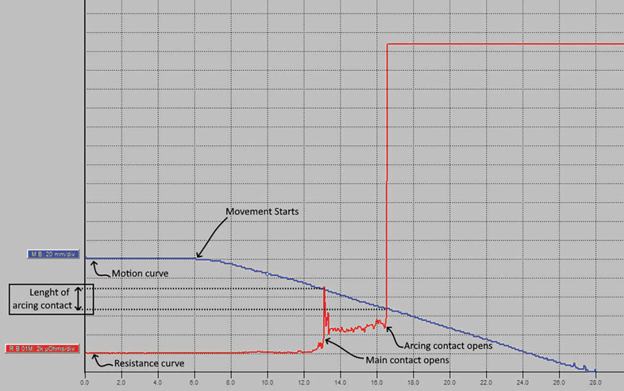
Figure 5: Typical Response of a DRM Test
Arcing contacts are used to endure the deterioration caused by the arc from opening the breaker. The wear and tear caused by the arc reduces the length of the moving arcing contact to the point that it becomes ineffective and needs replacement. To determine when to replace the arcing contact, it is necessary to know the length of the moving contact. This can be estimated from manufacturer graphs that show the estimated number of operations under fault current, but since it is an estimate, it may trigger major maintenance activity only to find it is not due for replacement, or it is too late, and the main contacts are already affected.
As an optimal alternative, DRM can be used to reliably determine the length of the arcing contact. When travel measurement is added to the test, the separation between the two spikes in resistance, measured from the travel curve, represents the remaining length of the moving arcing contact. Furthermore, significant deterioration of the arcing contact such as erosion or contamination will be reflected in the graph with multiple and high variations in the resistance instead of a smooth and flat curve.
DRM works well with both sides of the breaker grounded and when the breaker opens. Instead of a spike to infinite, it will show a spike to a resistance of higher magnitude equivalent to the ground loop resistance. In this sense, the technique also offers increased safety, and in addition to assessing the arcing contacts, it may be used to estimate breaker timing. However, it is not as accurate because it relies on a resistance threshold that needs to be adjusted below the ground loop resistance and above the arcing contact resistance. Both limits are usually not higher than 10 milliohms, and the transition occurs in less than 10 ms. A threshold setting within such a small range is difficult, especially if the measurement is affected by induced AC currents from surrounding live conductors.
First Trip
Circuit breakers can be used for multiple applications, and in most of them, the common status or position is closed. Because they are used mainly for protection and temporary isolation, they will be in open position only for hours or days, while they remain in closed position for months or even years. Since their operation depends mainly on mechanical drives, latches, and their corresponding lubrication, the lack of exertion can degrade their ability to respond in a matter of milliseconds upon a protection or control command.
Think about two identical breakers for a period of two years with the same initial mechanical conditions but with different operating regimes. Breaker A operates occasionally in steady, mild environmental conditions. Breaker B, which is permanently closed, does not operate over the two-year period and is exposed to harsh environmental conditions, i.e. the four seasons, high humidity, and extreme temperatures. After the two-year period, the operating performance of these two breakers will be different. The lack of exertion and the effect of the environment on lubrication and components could have greater impact on the performance of Breaker B compared to the effect of wear and tear on Breaker A. Specifically, the very first open operation of Breaker B could be slower and is likely to be out of tolerance; however, subsequent operations during the testing process may not show this reduced performance. When called upon to open, a breaker only has one opportunity: that very first operation after being closed for a long time. It doesn’t matter if the performance improves with additional operations.
Any detriment in performance will be reflected in the current signature of the trip coil. Any problem in the control circuit or the latching system driven by the coil armature will change the magnitude of the current or the timing of the sequence of events prior to releasing the latch. Opening a breaker that has been closed for a long time in preparation for testing usually goes unmeasured, the reduced performance is unnoticed, and the maintenance test may not prescribe any maintenance activity, masking an underlying and developing issue in the breaker. It is easy to conclude that measuring this first operation provides revealing information about the condition of the breaker.
This test is called first trip and can be done using a CBA with added current clamps. The test consists of measuring the current signature of the trip coil — or coils if the breaker is an independent pole operated (IPO) breaker — at the first operation after being in the closed position for a long time. The setup needs to be done at the control cabinet while the breaker is in service, however the setup is simple: one current transformer per trip coil, connections to the DC voltage supply to monitor the voltage while the breaker operates, and connection to the trip circuit to use it as a trig-in that starts the timer of the CBA (Figure 6). The measured signature is compared to a previous measurement, and the differences can determine whether there is a problem with the coil winding or armature, wiring or low-voltage issues, or problems in the trip latch or linkage system due to corrosion or lubrication issues.
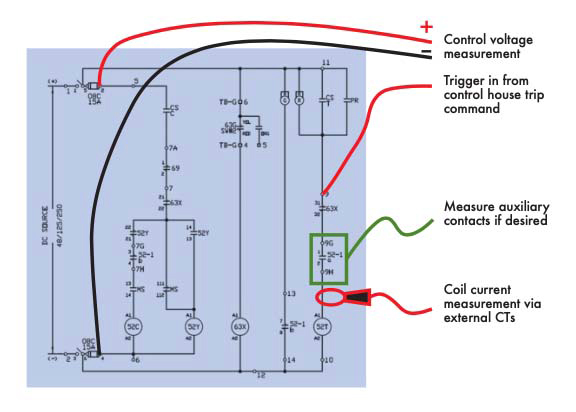
Figure 6: Setup to Measure First Trip
The opening time of the CB can also be measured by monitoring the secondary side of the protection current transformers (Figure 7). In any case, extra caution must be taken since there are live DC circuits in the control cabinet, and the mechanism may be inside the same cabinet. In this test, there are no connections to the main terminals, and travel is not measured unless the transducer is permanently mounted.
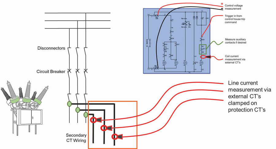
Figure 7: Setup to Measure First Trip and CB Opening Time
The greatest benefit of using first trip testing is to test real-world operating conditions. It is a quick test that does not require an outage and can be used to determine and prioritize offline maintenance actions using a condition based approach.
Motor Current
A spring-charge motor is employed to compress or expand springs to store potential energy for close and open operations. Malfunctions of the charging drive can cause deviations in motor operation, which in turn will be reflected in the electrical current that circulates during its operation. If this current is monitored and trended, issues such as lack of lubrication or a broken or fatigued spring can be determined.
Normally, operation of the motor occurs after a close operation and takes between 10 and 30 seconds. Due to the duration of the operation, a separate close test is added to the breaker test plan to measure the current separately from the rest of the timing operations. For the measurement, the current is monitored by one of the CBA’s analog modules using a current sensor clamped around the motor power supply. The power supply voltage is monitored by the control module.
The result will display the current graph along with parameters that characterize the motor voltage and current behavior such as motor running time and peak current (Figure 8). Analyzing the results evaluates the current shape and ensures that maximum current and time for charging springs are not exceeded compared to manufacturer specs, commissioning, or historic results.
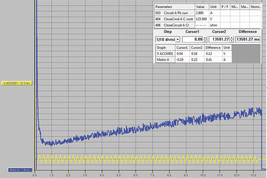
Figure 8: Motor Current Measurement Result
If the motor peak current is too high and/or motor charge time is too long, it could indicate that the charging mechanism requires more force than normal, e.g. due to lack of lubrication. Lower peak current and/or shorter motor charge time could indicate a broken or fatigued spring.
MV GIS Breaker Timing
Medium-voltage gas insulated switchgear poses a challenge when performing timing tests because the breaker is enclosed without any access to its terminals. Electrical access may be possible via cable terminal components, spare bays, or similar routes, but such access is limited to installation and commissioning phases. In the end, these options do not provide a practical option for routine or troubleshooting testing activities, and the entire switchgear needs to be isolated to be able to test using the conventional timing technique.
An alternative is to connect a CBA to the voltage detection system (VDS) through an adapter to determine the operating time of the breaker by detecting the instant in which voltage appears or disappears when closing or opening the breaker, respectively, for each phase.
Other parameters, such as coil current and auxiliary contacts, can be recorded, and other testing techniques like first trip and motor current are fully applicable to this type of circuit breaker while using the VDS to perform the test. Figure 9 shows the basic test setup where the control module is used to measure control voltage and trigger signals. The adapter is connected to the VDS on one end and to the timing module on the other end.
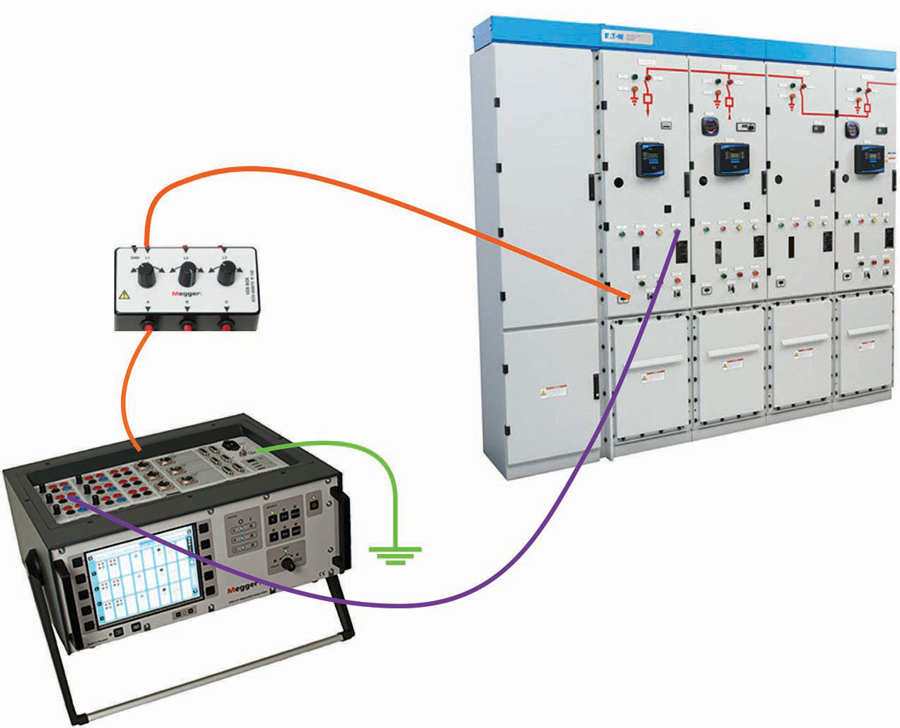
Figure 9: Basic Setup for VDS Testing
Figure 10 compares the results of close and open operations under conventional and VDS methods.
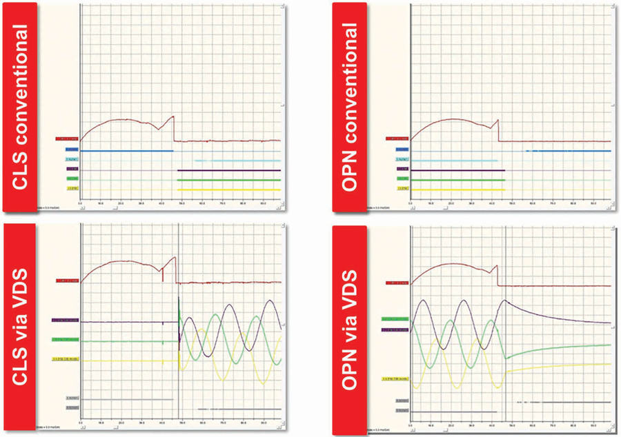
Figure 10: Close and Open Timing with Conventional and VDS Methods
This technique offers the ability to safely, efficiently, and accurately test breakers that are difficult to test with conventional techniques.
CONCLUSION
A circuit breaker analyzer is a multifunction instrument that, with the appropriate accessories and adapters, allows conventional testing, complementary testing, advanced testing such as DRM and motor current, and alternative techniques such as DCM to improve safety and efficiency. First trip testing can be used to prioritize maintenance activities. Other uses of a CBA not covered in this article include vibration analysis and testing synchronized switching of shunt capacitor or harmonic filter circuit breakers.
Not all circuit breaker analyzers are capable of performing all of these measurements. It depends on the module’s configuration and software capabilities. Selecting the right base instrument is critical to be able to add any additional feature in the future.
REFERENCES
R. Foster, V. Naranjo, and D. Carreño. “Testing High Voltage Circuit Breakers with Both Sides Grounded Using Dynamic Capacitance (DCM) Technology,” IEEE Electrical Insulation Conference (EIC), 2018, pp. 439-442.
Megger. Circuit Breaker Testing Guide, 2017. [ONLINE] https://embed.widencdn.net/pdf/plus/megger/eqalkjxt4v/CB_Testing_Guide_AG_2017_en_V0a.pdf.
 Volney Naranjo joined the Technical Support Group at Megger in 2011 as an Applications Engineer focusing on the products for transformer, low-voltage and high-voltage circuit breakers, batteries, and power quality testing. He participates in the IEEE Energy Storage and Stationary Battery committee and has published articles in conferences such as TechCon, PowerTest, TSDOS, BattCon, and EIC as well as technical magazines. Volney received his BSEE from Universidad del Valle in Cali, Colombia. After graduation, he worked in the areas of electrical design and testing and commissioning of power systems as a field engineer and project manager.