
Transformer differential protection based on ANSI 87 is one of the most common protection methods for large power transformers due to its outstanding speed and accuracy. However, given the complexity of this method when applied on delta-wye grounded transformers, mistakes made during the design and/or installation phases might not be detected promptly and can eventually cause an undesired operation — it could take months or years! This article analyzes the transformer differential protection schemes of two 25 MVA, 138/12.47 kV transformers feeding a main–tie–main scheme and investigates how improper installation and commissioning of a tie breaker caused a full outage at an industrial facility.
Differential Protection
Discussing differential protection starts with one of the most basic electrical laws: Kirchhoff’s Current Law (KCL). The KCL law states: “The algebraic sum of the currents entering a node (or a closed boundary) is zero.” In other words, the amount of current that enters an electrical node must equal the amount of current that exits the node. If these currents are unequal, an unintended path for current flow is present. Figure 1 shows a basic KCL representation.
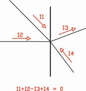
Figure 1: Kirchhoff’s Current Law
Differential relays apply KCL to protect electrical equipment (e.g. bus, transformer, line) by using current transformers (CTs), which must be installed at each connection point to obtain the total current summation. To perform the summation, each set of CTs must be brought into a protective device. A more modern approach allows the current values to be transmitted between relays using fiber optics (outside of the scope of this article).
It is important to note that CT polarity in these systems plays an important role: The CTs must be installed and wired so that the total current summation adds up to zero on load and external faults. This is only possible if the CTs at each end of the apparatus have opposite polarity and their resulting currents into the relay are 180 degrees out of phase. For a more thorough explanation of current flow and CT polarity, refer to “What is so Negative About Negative Sequence? Part 2,” NETA World, Summer 2018. Figure 2 shows a typical bus differential protection scheme.
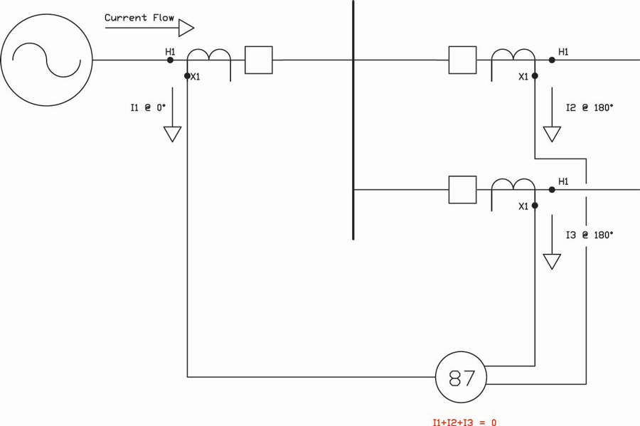
Figure 2: Bus Differential Protection Scheme
Transformer Differential Protection Using Electromechanical Relays
Transformer differential protection was originally performed using electromechanical relays. Many of these devices are still in service today and are now available with digital relays as well. These electromechanical relays require a set of currents at each side of the transformer (restraint currents) to undergo physical summation (operate current) to determine the fault location (internal or external) using a percentage characteristic method. For a detailed explanation of this method, refer to the ABB Type HU and HU-1 Transformer Differential Relays Instruction Manual. Figure 3 shows the restraint and operate currents in a differential electromechanical relay.
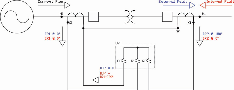
Figure 3: Differential Protection Using an Electromechanical Relay (Simplified)
One of the biggest challenges in transformer differential protection is the delta-wye grounded transformer configuration, which is widely applied. In this configuration, the delta-side windings connect one side of a given winding (i.e. the polarity side) to the opposite side of an adjacent winding (i.e. non-polarity side). With this connection type, currents entering the delta side of the transformer are considered to be phase-to-phase, while currents exiting the wye-grounded side of the transformer are considered to be phase-to-ground with all three of the latter windings grounded on one side. This configuration creates a 30-degree phase shift between the low- and high-voltage currents, which must be considered to properly apply transformer differential protection. Figure 4 shows the phase-angle relationship between the delta- and wye-grounded primary currents (A phase shown only). For a more detailed analysis, refer to Amberg and Rangel’s Tutorial on Symmetrical Components.
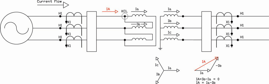
Figure 4: 30-Degree Shift on a Delta-Wye Grounded Transformer
Current Compensation and Electromechanical Relays
The previous section described a 30-degree phase shift between both sides of a transformer. To cancel out the CT secondary currents (and satisfy KCL), this shift must be addressed by wye-ground connecting the CTs on the delta side while delta connecting the CTs on the wye-grounded side. This CT delta configuration creates phase-to-phase secondary currents and therefore rotates the phase angles by 30 degrees. With this final shift, both sets of secondary currents have a phase angle difference of 180 degrees.
Note: Proper tap selection must be considered in transformer differential protection. However, in the misoperation being analyzed here, TAP1 and TAP2 were properly selected and did not contribute to the issue. Therefore, they will not be discussed further.
Figure 5 shows the proper CT configuration to be used for transformer differential protection with electromechanical relays. Due to the opposing CT polarity, the restraint currents entering the relay are 180 degrees apart.
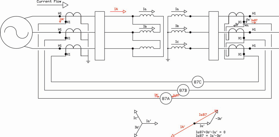
Figure 5: Delta-Connected Secondary CTs
Existing System
The system discussed in this paper consists of two incoming 138 kV transmission lines; each line feeds a 138 kV breaker. Each breaker then feeds a 25 MVA, 138 kV/12.47 kV transformer. On the low-voltage side, each transformer feeds a 12.47 kV breaker, which then feeds a 12.47 kV bus (identified as bus A and bus B). Each bus provides power to three different feeders (identified as 1, 2, and 3 on bus A and 4, 5, and 6 on bus B). A connection between bus A and bus B exists through a tie breaker connected to both buses.
CTs on the high-voltage side of the transformer are wye-ground connected (CT ratio of 100:5), while CTs on the low-voltage side of the transformer are delta connected (CT ratio of 1200:5). Since the 12.47 kV buses are part of the differential scheme by design, the CTs at the load side of each feeder, as well as one set of CTs from the tie breaker, must be connected to the 87T relays (every set connected in delta and paralleled). Figure 6 shows a simplified one-line diagram of the system.
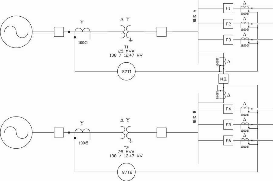
Figure 6: One-Line Diagram of Existing System (Simplified)
Phase-to-Ground Fault
On 11/29/2017, a C-phase-to-ground fault occurred downstream of feeder 5. A digital relay had recently been installed to protect feeder 5, and an event report was generated during the fault. The event report shows that the fault in the system lasted approximately three cycles and had a maximum current value of approximately 2,400 ARMS. During this fault, differential protection relays 87T1 and 87T2 tripped, and a full blackout was experienced at this facility (both 138 kV breakers opened). Figure 7 shows the oscillography generated by the feeder 5 relay during the ground fault.
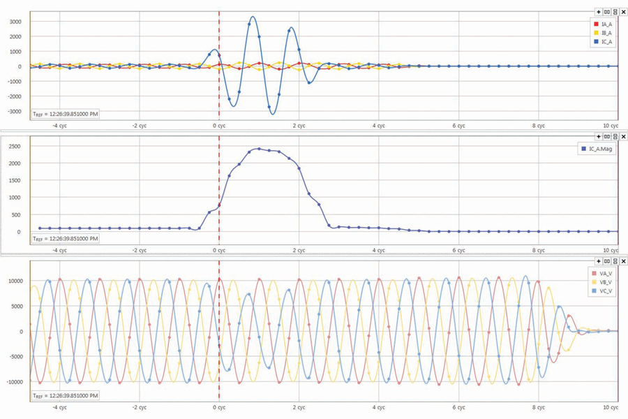
Figure 7: C-Phase to Ground Fault on Feeder 5
Troubleshooting
Site personnel identified the ground fault downstream of feeder 5, determined that both 87 relays had misoperated, and requested assistance from a third-party testing company to investigate the reason for the misoperations. The relay flags had been cleared, the lockout relays had been reset, the 138 kV breaker on the A side was closed (the system became partially energized), and loading was kept to a minimum until the root cause was determined.
The half of the system that was re-energized had a very low load; therefore, performing troubleshooting and commissioning was difficult. Additionally, because the 87T1 relay was electromechanical, it was not possible to obtain all restraint currents at once (a digital relay is able to capture these currents through a triggered event report). It was decided to troubleshoot the other half of the system that was still de-energized and isolated.
To verify the restraint currents flowing into 87T2, current was injected from the feeder breaker CT terminal blocks back into the relay. Given that the CT burden is much higher than the wiring and the relay inputs, it was not necessary to lift the wires prior to testing. A single balanced Amp was injected at each polarity connection point at the feeder 5 breaker CT terminal blocks (ST2X-1, ST4X-1, ST6X-1), and current measurements were taken with a digital clamp meter at a) the field wiring exiting the breaker and b) the restraint channel at 87T2. The measured currents were a) 1.0 Amp (expected) and b) 0.6 Amps (unexpected). Figure 8 shows a simplified schematic of the current testing performed at feeder 5 and the 87T2 relay (A-phase measured values only).
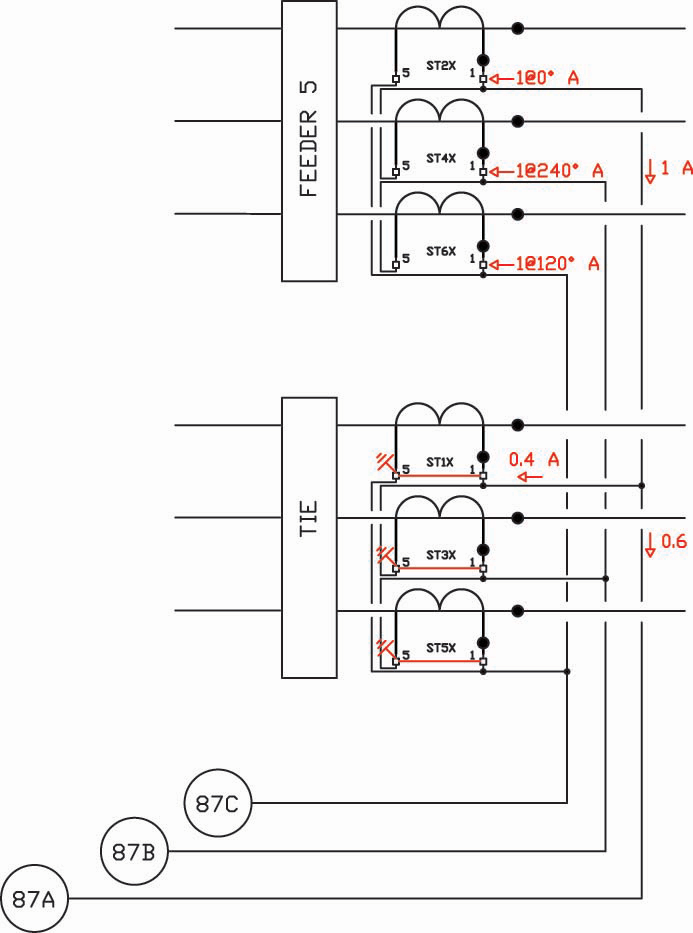
Figure 8: Current Testing at Feeder 5 Breaker (Simplified)
According to KCL, 0.4 Amps are flowing in an unknown path. Site personnel mentioned that the tie breaker had been replaced months ago due to aging. It was not put in service (i.e. the breaker and the isolating switches remained opened). However, connections were made to put it in service if needed. It was also mentioned that the 87T relays had nuisance tripped in the past and that these events began to happen shortly after this breaker’s installation. A visual inspection performed at the tie breaker’s wiring cabinet revealed that shorting screws had been installed at the CT shorting blocks connected to the 87T relays (Figure 9). Using a digital clamp meter verified that the missing 0.4 Amps were flowing into this unintended path. Since the CTs are delta-connected, their windings were shorted and a current path through this short was created (refer to Figure 8), which then created an outstanding operate current. This operate current would become high enough during an external fault to cause the 87T relays to erroneously declare an internal fault and trip.
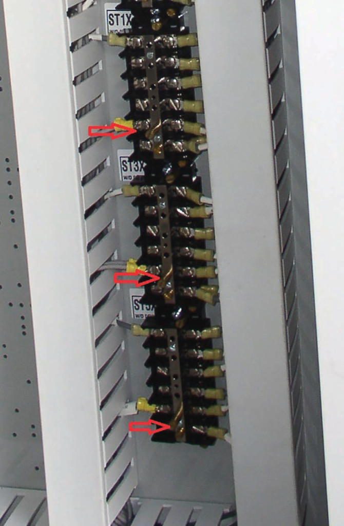
Figure 9: Tie Breaker CT Terminal Blocks, Shorting Screws Inserted
Lessons Learned
Several lessons were learned from these misoperations:
- When replacing substation apparatus, individual components that are part of the specific apparatus might affect the system. In the case of outdoor breakers, current transformers must be fully tested and commissioned prior to re-energizing the system to ensure proper operation.
- The use of electromechanical differential relays on a delta-wye grounded transformer adds complexity due to the CT delta connection on the wye-grounded side of the power transformer. These delta-connected CTs must never be shorted because the non-polarity side of one phase is always connected to the polarity side of another phase.
- Whenever CTs are introduced into a system but are not to be used, they can be connected wye-grounded and shorted out (they must never be left open).
- Protection systems (in this case, the differential relays) must be recommissioned anytime they are modified. One simple check is to meter the operate current upon loading the power transformer. A digital clamp meter can be used for electromechanical relays; for digital relays, a meter command should suffice. The mismatch between operate and restraint currents must be low and according to relay manufacturer specifications.
Conclusion
The process of replacing substation apparatus due to aging and/or limitations is very common, and all new instrumentation devices introduced into the system (i.e. CTs) must be fully tested and commissioned to ensure proper operation. Without proper testing and commissioning, mistakes can go undetected and eventually cause misoperations.
References
Alexander, C. and Sadiki, M. Fundamentals of Electric Circuits, 3rd Edition. The McGraw-Hill Companies, Inc., 2007.
Rangel, A. “What Is So Negative about Negative Sequence? Part 2.” NETA World, Summer 2018.
ABB, Inc. Type HU and HU-1 Transformer Differential Relays Instruction Manual, 1999.
Amberg, A. and Rangel, A. Tutorial on Symmetrical Components, 1st Edition (ebook). Schweitzer Engineering Laboratories, Inc. Accessed March 7, 2016 at https://cdn.selinc.com/assets/Literature/Publications/White%20Papers/LWP0010-01_TutorialSymmetrical-Pt1_AR_20130422.pdf.
 Alex Rangel is a Protection and Controls Engineer for Saber Power Services, LLC. Alex is NETA Level 4 certified, has been an IEEE member for 11 years, and has been a registered Professional Engineer (PE) in the state of Texas since 2014. He received a BSEE and an MSE from the University of Texas at Austin in 2009 and 2011, respectively.