
Safety in high-voltage substations is the highest priority for all personnel involved, and regulations and laws require all objects to be grounded on both sides before any maintenance work is performed. Failure to ground the circuit breaker (CB) on both sides creates risk of induced high voltages and currents at the ungrounded terminal. Eliminating this risk improves the safety of the test personnel and the test instrument itself.
If both sides are grounded, applying conventional main contact state detection methods is not possible because there is a parallel circuit through grounding cables and the grounding network, and the device would always detect a closed circuit. To overcome this obstacle, modern test methods applicable for testing a dead tank CB in these conditions are based on dynamic resistance measurement (DRM) or current injection through the grounding cables and simultaneous measurement of the current changes during CB operations.
However, these methods are not accurate or applicable for dead tank circuit breakers with a pole-pole-pole-neutral (P-P-P-N) grounding system. This paper presents a novel method for testing a dead tank CB with both sides grounded that would be applicable for all types of grounding systems. The method is based on DC current injection (about 20–30 A per phase) through the main circuit and measurement of the response signals on the secondary terminals of breaker-mounted current transformers (CT).
Introduction
Regulations and laws related to maintenance and testing in high-voltage substations require all objects to be grounded on both sides during work. To measure operating times (O, C, O-C, CO, etc.) on the dead tank CB’s main circuit with the conventional testing method, grounding cables must be removed from one side of the circuit breaker. However, the procedure to remove cables is unsafe and time-consuming and often not practical — and is therefore considered undesirable by test personnel in utilities. There is also a risk of inducing high voltages at the ungrounded side of the circuit breaker when the circuit breaker is in the open position during testing.
If the grounding cables are not removed or disconnected, a conducting circuit parallel to the tested main circuit path is formed (Figure 1). Therefore, when the circuit breaker is in an open position, there is a closed circuit through the grounding cables and grounding network. The resistance of this circuit usually varies from a few mΩ to tens of mΩ. The main arcing contacts are first to close and last to open the main circuit, so they define the initial closing and opening operations of the circuit breaker. The resistance of arcing contacts ranges from a couple of hundreds μΩ to a couple of mΩ, so it is still possible to distinguish this resistance from grounding resistance and use it to determine the state of the main circuit.
One existing method in the market that uses this approach to measure timing in dead tank circuit breakers with improved safety is based on dynamic resistance measurement (DRM). The other method is based on inducing voltages across grounding cables and measuring the current change through the grounding cables during circuit breaker operation. These two methods are applicable for testing a dead tank circuit breaker with a pole-neutral (P-N) grounding system (Figure 1), where each single pole of the circuit breaker is separately grounded on both sides.
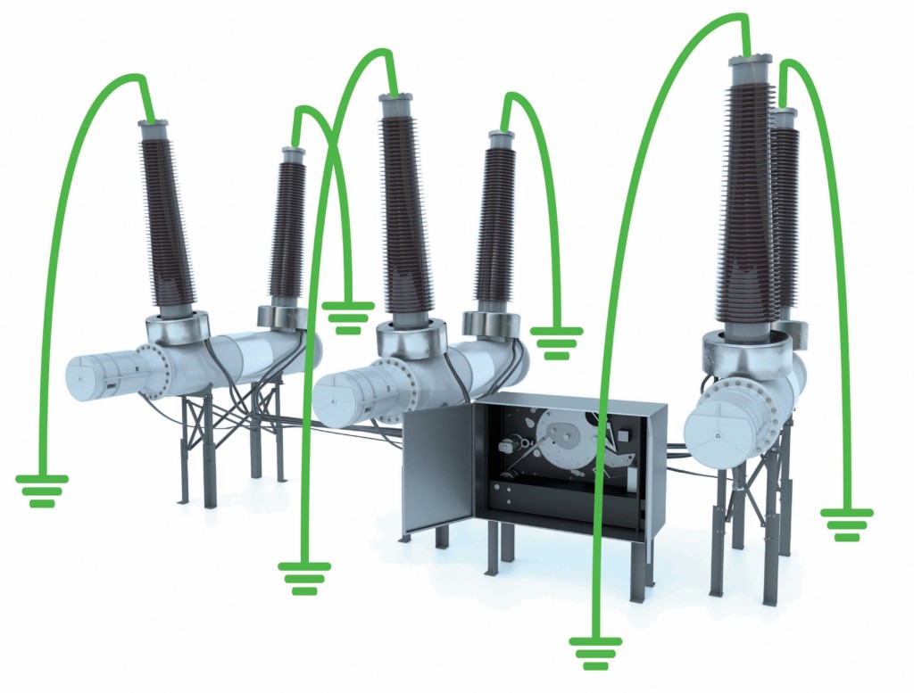
Figure 1: Dead Tank Circuit Breaker with P-N Grounding System on Both Sides
However, these test methods are not fully applicable or reliable for measuring operating time on a dead tank CB with a P-P-P-N grounding system (Figure 2), which is very popular in the United States. If the DRM method is used in this situation, the same result would be obtained for the main contacts of all three poles, even if the real operating time of the main contacts is different. The method based on voltage generation and current measurement through the grounding cables is not applicable since the unique pair of grounding cables required to measure current changes in each pole of the circuit breaker does not exist.
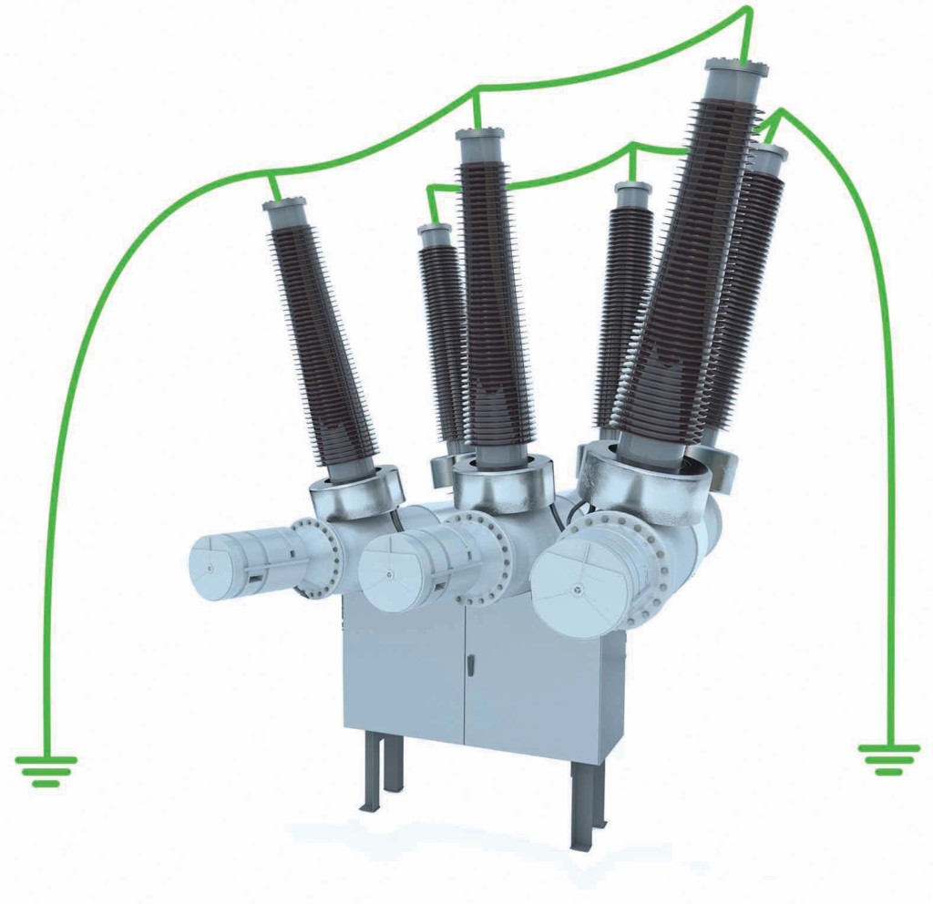
Figure 2: Three-Pole Controlled Dead Tank Circuit Breaker with P-P-P-N Grounding System on Both Sides
An Innovative Solution
It would be desirable to develop a universal test method that would be applicable for both P-N and P-P-P-N grounding systems in dead tank CBs. Such a method is proposed as a solution for testing gas-insulated substation (GIS) circuit breakers with both sides grounded as described by Ostojic and Secic in “Improving Safety in Operation Time Measurement.” This method combines the resources of two existing CB test methods: a) dynamic resistance measurement (DRM) as described by Secic and Milovic, and b) the first-trip test proposed by Obarcanin and Secic.
The DRM test consists of injecting high DC current, usually 100A or even up to 500A, through the breaker contacts and simultaneously recording the voltage drop across the main circuit during CB operation. The proposed new method is also based on the injection of the DC current but requires only about 20–30 A per phase. We suggest using the same power source used for the DRM test method, which in this case is a voltage-controlled DC current source with high output current based on state-of-the-art power electronic converters. It should be noted that a high-power battery, such as Li-Po or similar, can also be used as a current generator in this case. For this test method, one power source is enough. A connection from a power source to the circuit breaker terminals must be performed with two current cables that each branch into three cables, thus providing even current distribution through all three main contacts (Figure 3).
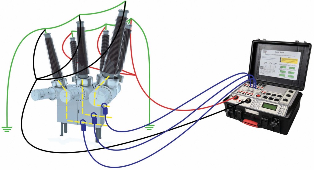
Figure 3: Proposed Method for Dead Tank Circuit Breaker with P-P-P-N Grounding System on Both Sides
In the first-trip test, contact timing is calculated by measuring the AC waveform (voltage or current) on the secondary of the current transformer while the CB is still in service. In the proposed method, the CB is disconnected from the grid. However, the same approach for contact timing is used as for the first-trip test.
Current transformers (CTs) are an integral part of a dead tank CB. The primary terminal of these elements is located at the bushings, while the secondary terminal is in the auxiliary circuit (see Figure 3). These accessible CT secondary terminals can be used to measure operation time in dead tank circuit breakers. While DC current is generated through the main circuit during CB operation, the measuring instrument should record either the current or voltage response on the CT secondary based on which instant of the CB contacts can be detected. Currents at a CT’s secondary can be recorded using current probes based on the Hall effect or using a transformer.
Case Study
To prove the applicability of the proposed novel method, an experiment was conducted on an improvised test station. An air-type circuit breaker, model AT-16 manufactured by Terasaki, was used in the experiment. These types of modular switchgear are equipped with current transformers. A test of a dead tank CB with a P-P-P-N grounding system on both sides was simulated using grounding system cables of 4 mΩ resistance.
The required value of the current was generated by the built-in power source in the test instrument. The connection from power source terminals to circuit breaker terminals was performed with current cables that branch into three cables, similar to the test setup shown in Figure 3. All three CT secondary currents were measured by transformer-based current probes where the outputs were connected to the analog voltage channels of the test instrument.
DC source current generation and secondary CT current measurements were synchronized during circuit breaker operation. The results of close and open tests are shown in Figure 4. For the close operation, the instant of contact touching represents the measured CB closing time, which can be determined by the moment when CT secondary currents start to appear (around 38 ms). For the open operation, the instant of contact separation represents the measured CB opening time, which can be determined by the moment CT secondary currents reach the latest turning point (around 21 ms).
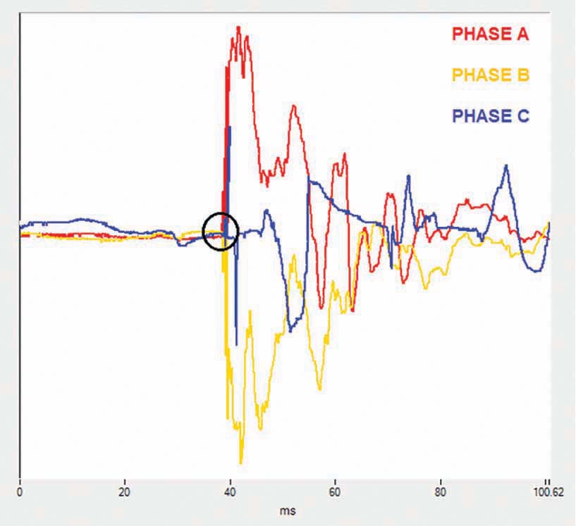
Figure 4a: CT Secondary Current Responses
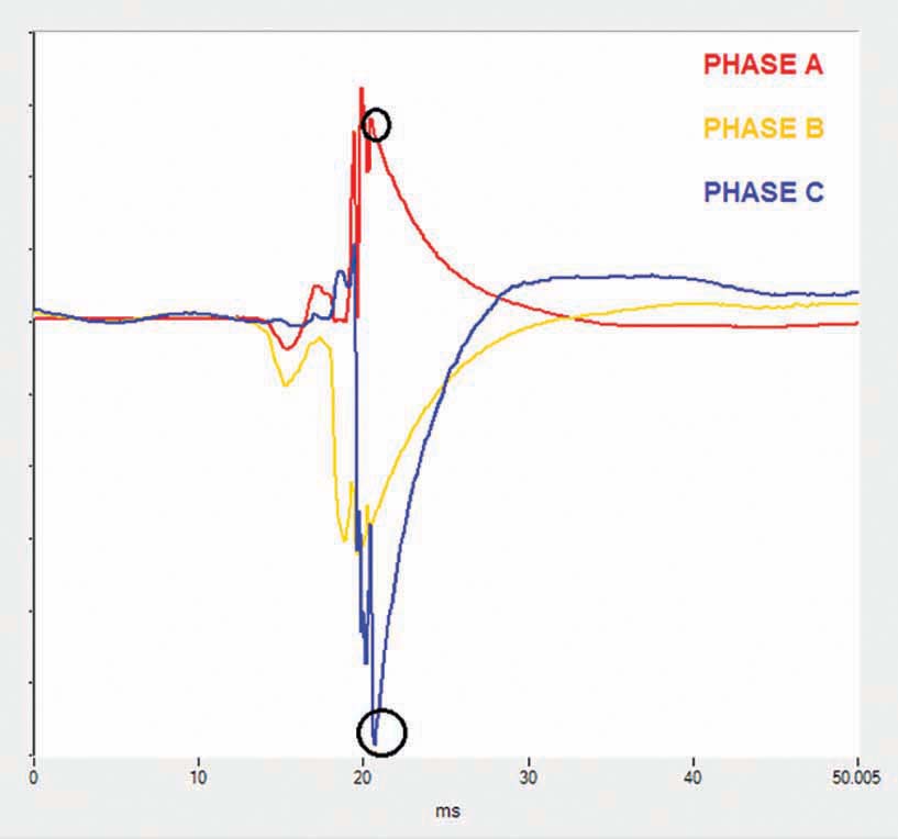
Figure 4b: CT Secondary Current Responses
Following these measurements, the grounding cables were removed from the breaker, and the measurements were repeated with a conventional CB analyzer with only one side of the CB grounded. Results for close and open operations are shown in Figure 5. The experiment was repeated until a considerable amount of data was gathered. Data analysis led to the conclusion that the measured operation time of the breaker matches with moments that can be extracted from the waveform obtained from the current signal recorded on the CT secondary wires.
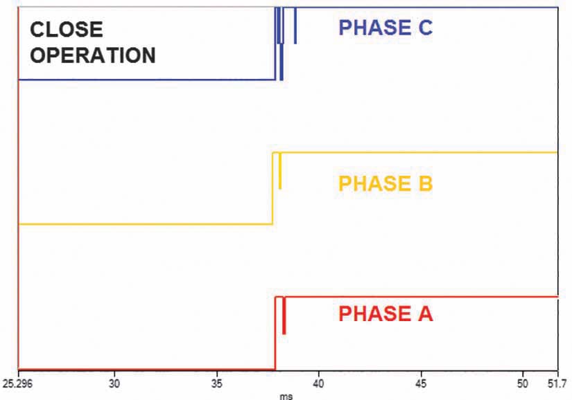
Figure 5a: Results with conventional timing
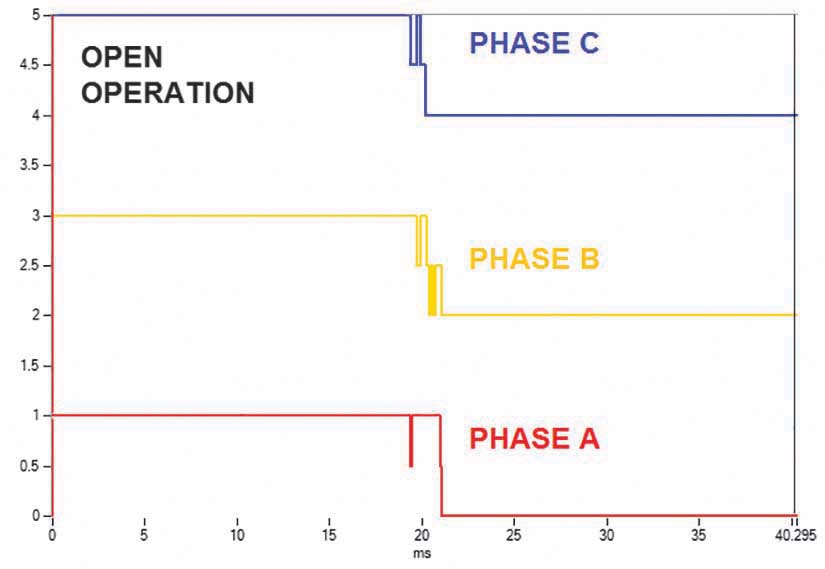
Figure 5b: Results with conventional timing
Conclusion
P-N and P-P-P-N are the two most common systems used to ground dead tank circuit breaker terminals during maintenance and testing. Currently, two methods exist to measure operation time of a dead tank CB with both sides grounded. However, these methods are applicable and reliable only for the P-N grounding system. By combining the resources of two already known test methods — dynamic resistance measurement and the first-trip test — it is possible to measure the operation time of a dead tank CB with improved safety conditions for P-N and P-P-P-N grounding systems. This proposed method does not require changing or adjusting the grounding system when using the test method. Thus, safety risks to test personnel are avoided, and the testing procedure is accelerated.
References
IEEE Std. 510-1983, IEEE Recommended Practices for Safety in High-Voltage and High-Power Testing.
R. Ostojić, A. Šečić. “Improving Safety in Operation Time Measurement Procedure for Circuit Breakers in Gas Insulated Substation,” Research Disclosure, 2019.
A. Šečić, B. Milovic. “Dynamic Resistance Measurement Method Applying High DC current,” at CEATI Circuit Breaker Test & Maintenance Workshop, 2014, Palm Desert, CA.
K. Obarcanin, A. Šečić. “The Embedded Handheld System for Contact Timing Parameter Extraction in Online Mode for the High Voltage Circuit Breaker Condition Assessment,” 2018 International Symposium on Industrial Electronics (INDEL) 2018, DOI: 10.1109/INDEL.2018.8637631.
 Radenko Ostojić is a test and diagnosis engineer at DV Power — Sweden in the field of circuit breaker testing and maintenance. He has been employed at DV Power since 2010 and works on the improvement of circuit breaker testing equipment and development of new methods for circuit breaker testing. Radenko’s area of special interest is testing of circuit breakers in enhanced safety conditions, which implies testing of circuit breakers with both terminals grounded. He earned his BS in electrical engineering at the University of East Sarajevo.
 Adnan Šečić is an R&D Engineer at DV Power — Sweden. As a project leader, he is responsible for development of the circuit breaker analyzer and timer (CAT) device series. Adnan received his BS in electrical engineering and MS in electronics, electrotechnics, and automation (EAA) from the University of Sarajevo, Bosnia and Herzegovina, and is in the final stage of PhD studies at the Faculty of Electrical Engineering and Computing in Zagreb, Croatia.