

This article presents a high-level overview of performing practical, functional checks and testing on digital substations using generic object-oriented system events (GOOSE) and sampled values (SV).
The integration of renewable energy resources into the power system has created a pressing need for advanced technologies that can effectively monitor, protect, and control these assets. Digital substations, along with their associated technologies, have emerged as a crucial solution to meeting these requirements. As a result, the adoption of digital substations has accelerated in recent years, driven by the demand for improved flexibility, enhanced functionality, and efficient management of renewable generation assets.
IEC 61850
One of the key components in digital substation implementations is the IEC 61850 standard series. This standard provides a comprehensive framework for communications networks and systems in substations, addressing various areas of interest for protection and control engineers and technicians. Among the various parts of the IEC 61850 standard, two widely used components are generic object-oriented system events (GOOSE) and sampled values (SV). Figure 1 shows a simplified substation network architecture diagram showing the station and process buses.
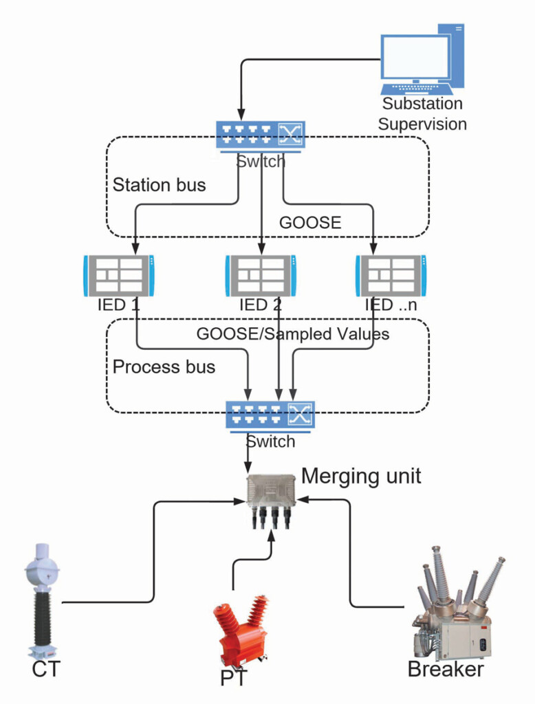
Figure 1: Simplified Substation Network Architecture
Generic object-oriented system events (GOOSE) is a communication mechanism defined in the IEC 61850 standard. It enables a fast and reliable exchange of status information and events between intelligent electronic devices (IEDs) in a substation. GOOSE messages are multicast-based, allowing for high-speed data transfer with low latency. This makes GOOSE particularly valuable in applications that require quick and synchronized protection actions, such as fault detection and tripping.
In the context of renewable energy integration, GOOSE finds significant application in scenarios such as grid stability management. For instance, when a fault is detected in a renewable generation unit, a GOOSE message can be transmitted to all relevant IEDs in the substation, triggering immediate protective actions, such as isolating the faulted section or adjusting the control parameters of the renewable unit. This seamless and rapid communication facilitates effective fault management, minimizing downtime and optimizing the performance of the overall power system.
Sampled values (SV) is another essential aspect of the IEC 61850 standard. SV allows the transmission of analog quantities (e.g., voltage and current) sampled at high rates, ensuring an accurate representation of the power system’s dynamic behavior. With SV, real-time information about the electrical parameters of the substation can be exchanged between IEDs, enabling precise monitoring and control of renewable energy resources.
In practical applications, SV is vital for tasks such as dynamic grid modeling and synchronization. For instance, when integrating a large-scale wind farm into the power grid, SV allows the precise measurement and transmission of voltage and current waveforms from the wind turbines to the control center. This information enables advanced algorithms to accurately model and analyze the grid’s dynamic behavior, ensuring optimal grid stability and effective control of the renewable generation units.
GOOSE
Generic object-oriented system events are multicast messages exchanged over an Ethernet Network, which means that a single message can be simultaneously received by multiple devices within the substation. This allows efficient communication between intelligent electronic devices (IEDs) without needing point-to-point connections.
Since GOOSE messages enable the exchange of real-time event data between IEDs within a substation, they are typically used for high-speed, time-critical applications where fast and reliable communication is required, such as protection schemes or interlocking systems.
Examples of real-time event data exchanged using GOOSE messages are status changes, measurements, or control commands. These events are typically related to the operation and control of devices within the substation. More practically, this means that GOOSE messages replace logic signals like pickup, drop-out, trip, close, reclose, lockout, breaker positions, etc.
As stated in its name, GOOSE uses an object-oriented data model where data is organized into objects with defined attributes and behaviors. This enables standardized representation and interpretation of data across different devices. In other words, it’s easier to know where the trip signal originated because the identification of the IED is contained in the trip message. Try doing that with a wire!
IEDs subscribe to GOOSE messages from other IEDs and publish them so others can subscribe.
In digital substations, traditional logic signal wiring is replaced by GOOSE messages. IEDs only need to connect to an Ethernet network using a fiber optic cable or a regular ethernet cable. Protection test sets connect to the substation network to subscribe to GOOSE messages present on the network and to publish their GOOSE messages. To aid in testing, GOOSE messages published by test sets can be copies of messages published by other IEDs.
Sampled Values
Sampled values are multicast messages exchanged over an Ethernet network called process bus that are used to replace analog signals. In a traditional IED, current transformer and voltage transformer (CT and VT) analog signals are connected directly to the IED’s current and voltage inputs, where those signals are sampled and converted to their digital equivalent using different digital signal processing technologies.
Sampled values eliminate the need for analog to digital conversion at every IED connected to a given CT or VT, putting the work of converting the analog signals into the digital world in the hands of the instrument transformer itself or a device called a merging unit(MU). In this scenario, sampled values replace traditional wiring, so instead of hard-wired connections between the CT/VTs and the IED, now the CT/VTs produce their digital signals in the form of sampled values or are connected to a merging unit that samples the analog signals from the CT/VTs and publishes these on a network in the form of SV streams.
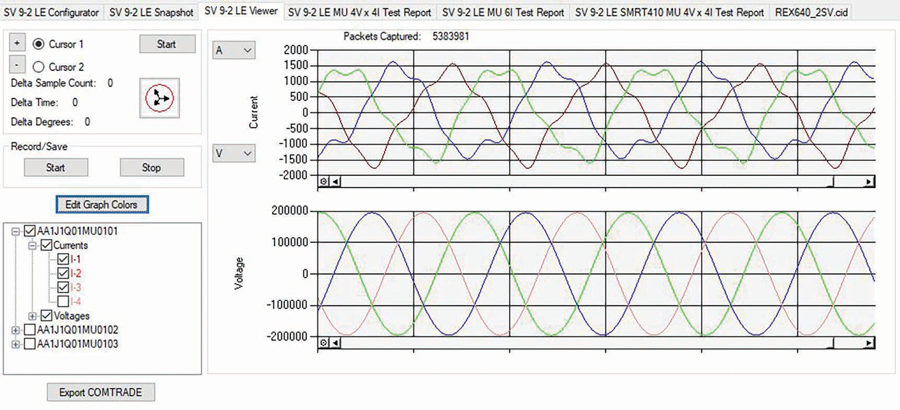
Each stream has eight channels since it contains values from four currents and four voltages. Figure 2 shows three SV streams with four currents and four voltages each. This is a typical output of a sampled values simulation tool.
Another important issue when using sampled values is the time synchronization signal. In a traditional analog substation, the voltage and current signals are automatically synchronized to the system frequency, and the only phase differences are those introduced by CTs and potential transformers (PTs). In this scenario, each IED takes care of its analog-to-digital conversion process, so each IED knows when each sample was taken because they took it! However, when the analog to digital conversion happens at the CT/PT level or a merging unit, each sample must be stamped with the time that sample was taken. This requires the use of a system-wide synchronization signal. In sampled values applications, precision time protocol (PTP) is used. An excellent and straightforward explanation of the synchronization process can be found in Bettler et al. [1]
Conventional installations address IED synchronization using IRIG-B, which requires running a coaxial cable to each IED in the substation. In contrast, using PTP, the time synchronization signal is supplied to the IED using the same Ethernet/optical fiber connection used to provide GOOSE and sampled values, adding to the greatly reduced wiring requirements achieved with this substation implementation.
IEDs subscribe to the sampled values streams that contain the signals related to the device they are supposed to protect. For instance:
- A-line protection relay will subscribe to the stream that contains the values sampled from the CT/VT connected to the line it is supposed to protect.
- A transformer differential relay will subscribe to the streams containing the CT/VT from both sides.
Multiple SV streams are circulating on the substation’s process bus at any given moment.
IEDs can subscribe to both sampled values and GOOSE messages.
Since the information published on the network is in Ethernet packages, it is easy to integrate nonconventional instrument transformers like an optical CT or a Rogowski coil CT into existing substations to improve performance.
Test sets can produce simulated sampled values signals that can be injected into the substation network to test the behavior of IEDs and perform end-to-end testing of the protection system. A test set can also be used to verify the accuracy of merging units by injecting current and voltage signals into the MU’s analog inputs and comparing the SV stream produced by the MU to the reference SV stream provided by the test set. This process is described in more detail below.
TESTING
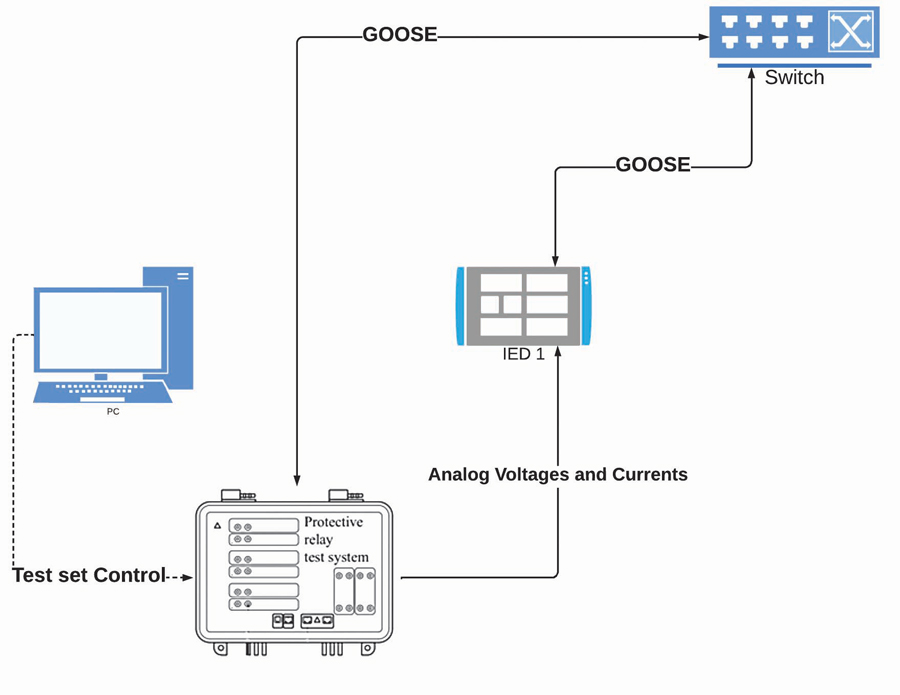
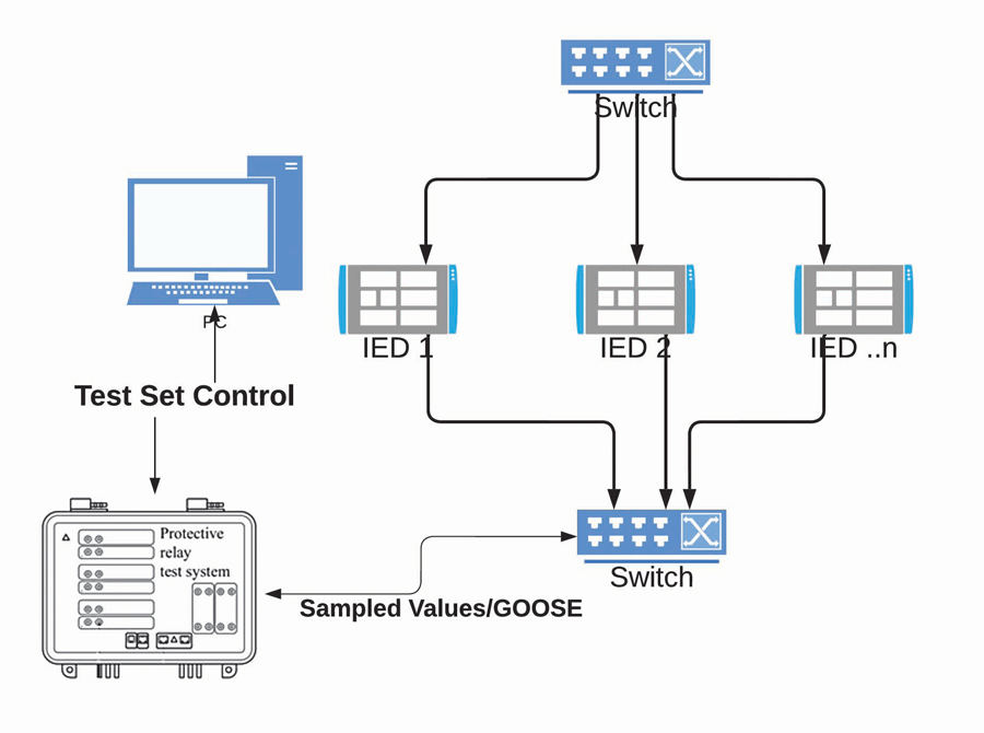
Digital substations are sometimes built using a hybrid approach that includes GOOSE messages for logic signals but still has analog signal connections. In this case, testing will involve producing analog signals from a protection relay test set, injecting them into the IED under test, and verifying the generation and reception of the GOOSE message or messages associated with the function under test. This is similar to traditional protection testing, except now we are getting the trip signal, status, etc., from an Ethernet network as a GOOSE message. Figure 3 shows a typical connection diagram for a test using analog injection with GOOSE trips.
A typical test scenario can involve the following steps:
1. Getting GOOSE messages available on the system under test:
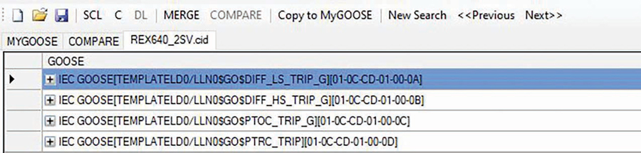
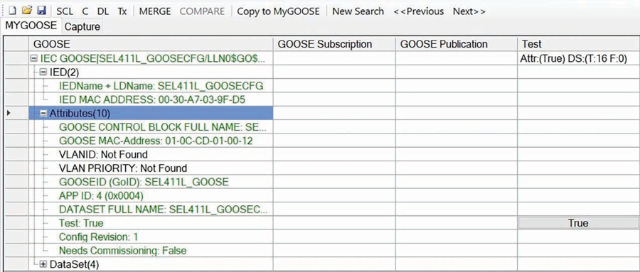
a. From an SCL file containing information about the substation network configuration, including the GOOSE messages as can be seen in Figure 4.
b. From the network itself, use a GOOSE sniffer to capture GOOSE messages from the network.
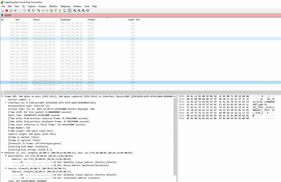
i. It is possible to use a general network sniffer like Wireshark for this task. This will show us when the GOOSE messages are generated and can be used to analyze the network traffic, GOOSE packages, etc. This can be seen in Figure 5.
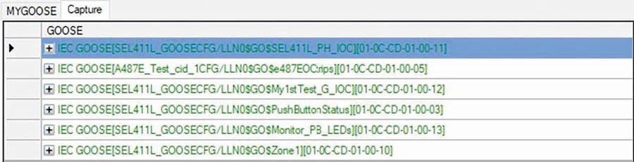
ii. There are advantages to using specialized GOOSE testing software like the one shown in Figure 6. This type of software automatically organizes the GOOSE messages by sender and shows the changes in the status of the message content.
2. Comparing GOOSE messages on the network with the SCL file. This is done to verify that only GOOSE messages in the SCL file are available on the network and that there are no Messages on the SCL file missing from the network.
3. Setting up the test mode and behavior on the devices under test. A properly executed test should only exercise the devices under test. Both the test set and IED under test must be set to produce GOOSE messages with the test bit enabled. A proper explanation of this complex topic exceeds the limits of this article. A good introduction to this topic can be found in E. Hernández, et al.[2]
4. Configuring a test set to subscribe to or publish the GOOSE messages under test (e.g., if we are testing an overcurrent function, have the test set subscribed to the GOOSE messages that contain the trip and pick-up signals, then assign those to the test set’s logical binary inputs. This is similar to connecting the relay’s physical digital output to the test set’s physical binary input and masking the output on the relay with the desired trip signal, except the process is now logical rather than physical. You don’t need a screwdriver anymore! Figure 7 shows an example of this type of configuration.
5. Produce the test cases for the functions under test, (e.g., overcurrent, under voltage, etc.), and verify the protection function’s operation using GOOSE messages. When an overcurrent condition is injected into the relay, it will produce and publish a GOOSE message containing the trip information, which will be received by the test set via its ethernet cable.
6. As with any other testing, proper documentation is key at every step during the testing process. Since wiring changes are now made virtually via GOOSE message subscription, VLAN routing, etc., it is extremely important to keep an accurate record of all the configuration files of all IEDs on the substation and the SCL files for the whole system.
When testing with sampled values, we have two typical cases.
- Testing the merging unit, which produces the sampled values from the CT/PT on the substation yard and injects them into the network.
- Testing the IEDs that use the sampled values already on the network.
Let’s look at both cases in detail.
Sampled Values: Testing the Merging Unit
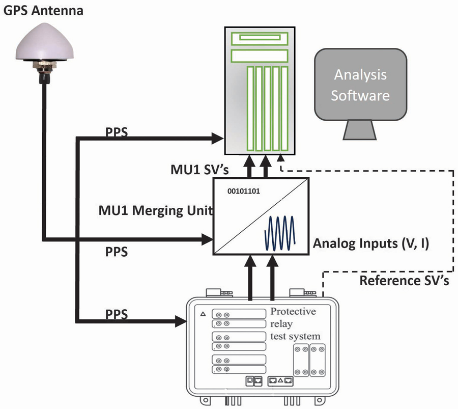
To test the merging unit, we need to inject voltages and currents into the merging unit’s analog inputs and read the sampled values produced by it. Figure 8 shows a connection to test the MU proposed by the PSRC.[3]
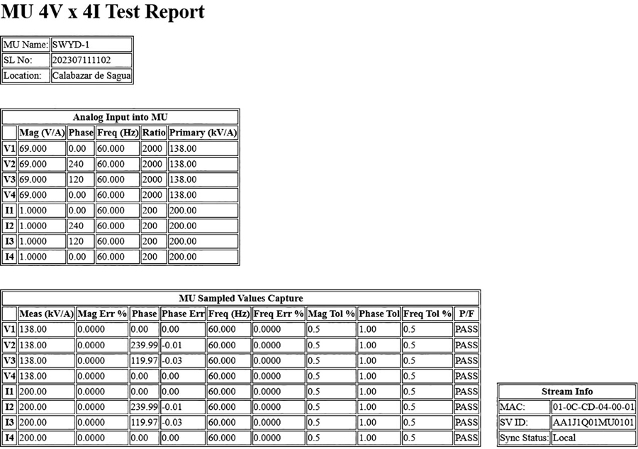
The merging unit is evaluated by comparing the generated sampled values with the actual analog magnitudes injected into the MU analog channels. A merging unit test report can be seen in Figure 9.
It is important to mention that since the merging unit serves as a pathway between the analog and digital worlds, it can accept and produce GOOSE messages and sampled values. There could be elements in the switchyard, such as older breakers that may not have a native digital interface, and the merging unit should be able to convert the trip/close signal in the form of a GOOSE message from an IED into a coil signal the breaker can use to open/close.
Conversely, the breaker should be able to communicate its status to the digital world. For this, the 52a/b contacts are wired into the merging unit, producing appropriate GOOSE messages indicating breaker status. Testing the generation and subscription to GOOSE messages is possible by activating the binary inputs of the MU, verifying the generation of the GOOSE messages, conversely injecting the GOOSE messages into the network connected to the merging unit, and verifying the activation of the appropriate binary outputs on the MU.
Sampled Values: Testing the IED
To test the IED, sampled values are injected into the network from a test set with the stream format expected by the IED under test. Figure 10 shows a connection diagram for sampled values injection. Remember that to use the sampled values, IEDs subscribe to them; they will only use sampled values streams from the appropriate source. The test set must emulate the sampled values produced by said source.
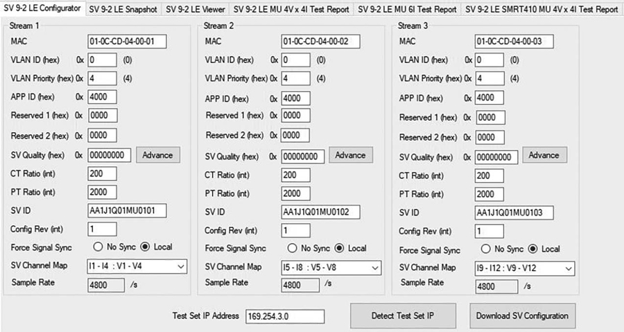
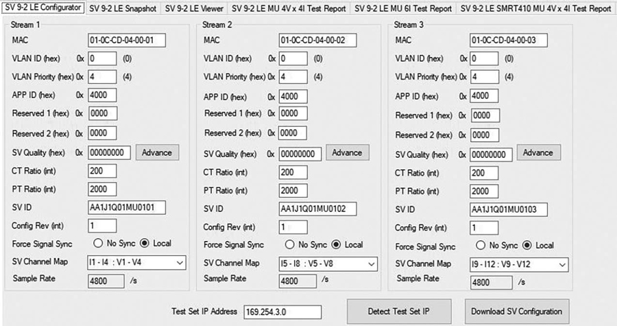
For this, the test set can get the sampled values stream format from the SCL file or an IED’s CID file, but it can also accept the configuration of arbitrary sampled values streams. Figure 11 shows an example of the configuration of sampled value streams on a test set.
In this scenario, the test set will produce sampled values with overcurrent, over/under voltage, distance, differential faults, etc. A test set capable of producing the same kinds of test cases for analog and sampled values can be used but is not required for this case.
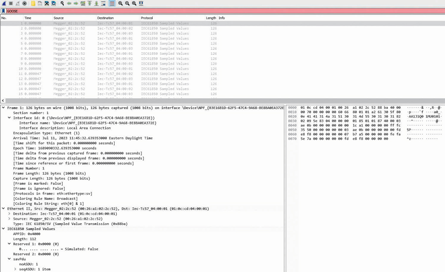
Once the sampled values are injected into the networks, they can be monitored using Wireshark, as seen in Figure 12.
A better option for protection testing is using one of the many specialized sampled values monitoring softwares, as seen in Figure 13. This software typically has the advantage of letting us see the actual waveforms being injected into the network, allowing manipulation of views, getting recordings, and exporting recordings into COMTRADE format for later use.
Since injecting sampled values on a network makes those packages available to every IED connected, verifying that only the appropriate IEDs can see or subscribe to specific SV streams becomes important. Other IEDs on the same network that are not subscribed to these SV streams should be blind to them. Since it is possible to simulate different sampled values streams from the same test set connected at the same point on the network, it is possible to test all the IEDs connected to the network without having to relocate the test set and make connection changes such as moving between junction boxes, etc. This flexibility greatly reduces testing time and minimizes the potential for connection errors.
CONCLUSION
We have shown a high-level perspective on the benefits and challenges of testing using IEC 61850 GOOSE and sampled values in digital substation installations. One of the more obvious benefits of the standard includes reducing cabling, trenching, grounding considerations, and hard-wired connections, to name a few.
For testing using GOOSE messages, we have shown how it is conceptually similar to traditional wired testing. Since GOOSE messages are physical binary inputs and outputs, we need to know how to get them from the network or an SCL file and how to use them to perform functional tests of the IEDs involved.
Sampled values take the role of analog current and voltage signals on the network, and testing them is also conceptually similar to testing traditional substations. We have shown those similarities and differences and how to test them. In particular, we have shown how to test a merging unit by injecting analog values and physical binary inputs and outputs and verifying the generation of sampled values and GOOSE messages.
We have also shown the various uses of general networking software and the advantages of specialized 61850 testing software for GOOSE and sampled values.
REFERENCES
[1] J. Bettler et al. “Performance of IEC 61850 Sampled Values Relays a Real-World Fault Performance of IEC 61850 Sampled Values Relays for a Real-World Fault,” Western Protective Relay Conference, October 2022. [2] E. Hernández, T. Whitesell, and K. L. Wyszczelski. “A Practical Guide to Substation Testing Using IEC 61850 Mode and Behavior,” Power and Energy Automation Conference, Seattle, Washington, March 2020. [3] PSRC, PES-TR84 Application Testing of IEC 61850 Based Systems, 2020.
Abel Gonzalez has worked for Megger, LTD in Markham, Ontario, as a Senior Relay Applications Engineer since 2013. His research areas include analyzing electric power systems’ ratio, control, and protection. He is currently a member of IEEE-PSRC. Abel previously worked as an Assistant Professor for the Faculty of Electrical Engineering at the Universidad Central de Las Villas, Cuba, where he taught courses in electrical drives and power electronics. He also worked as a Tele-Traffic Engineer, Control Engineer, and Head of the Marketing Department for the Cuban Telecommunications Company; as a Marketing and Electrical Engineering Professor for the Universidad Central de Las Villas, Cuba; and as a Design Engineer for Arteche Medición y Tecnología in Zapopan, Jalisco, Mexico, and Curitiba, Brazil. Abel received his BS and MSc in electrical engineering from the Universidad Central de Las Villas, Cuba.

Michael Wilson has been a Senior Relay Applications Engineer at Megger Group since May 2022. While working at United States Steel Corporation in the Electrical Operations & Services Division, he earned his MS in management from Indiana Wesleyan University. Mike previously worked as an engineering consultant and NERC compliance manager for a cooperative outside Chicago and as a Lead Testing and Commissioning Engineer for TRC Companies and Burns & McDonnell. He is a student pilot member of IEEE and the Experimental Aircraft Association (EAA). Mike earned his BS in electrical engineering from the University of Missouri – Rolla (now Missouri University of Science & Technology).

Dhanabal Mani joined Megger India in 2009 as an Application Manager, delivering advanced Megger relay testing solutions focusing on digital substation solutions. He joined Megger Dallas in 2012 and has been the Director since 2020, driving the company’s success by ensuring reliable relay testing solutions. With over 22 years of experience in protective relaying and commissioning in power systems, Dhanabal has published numerous articles and presented at prestigious international conferences. He previously led the commissioning of India’s groundbreaking 400 kV IEC 61850 substation in Madhya Pradesh while working as the Lead Commissioning Engineer at ABB India Ltd and as an R&D Engineer at ABB Ltd in Sweden, where he developed customized relay applications. Dhanabal obtained his BS from Bharathiyar University in India.