
Transformer differential protection (ANSI 87), which operates on Kirchhoff’s Current Law (KCL), is one of the most common protection methods for large power transformers. This method was first implemented using electromechanical relays built with instrument transformers and other electrical components to convert secondary currents from amperes to per-unit to apply KCL properly. For a detailed explanation of the operation of these relays, refer to the ABB HU and HU-1 Instruction Manual.[1]
This article analyzes the transformer differential protection of a dual-source system with two 25 MVA, 138 / 12.47 kV transformers feeding a main-tie-main scheme, and how the accidental partial demolition of the current circuit wires feeding one of the relays caused a delayed outage at an industrial facility.
EXISTING SYSTEM
The system discussed in this paper, as well as a detailed explanation of KCL and electromechanical differential protection, was initially described by A. Rangel.[2]
- This is a dual-source 138 kV system.
- Each source feeds a 138 kV high-voltage (HV) breaker.
- Each HV breaker feeds a 138 kV / 12.47 kV transformer.
- Each transformer feeds a 15 kV medium-voltage (MV) breaker (Main A and Main B).
- Each MV breaker feeds an MV bus (Bus A and Bus B).
- Each bus has three feeders, with a normally open tie breaker between Bus A and Bus B.
- Each transformer has an electromechanical differential relay. Due to the transformers’ configuration, the MV-side current transformers (CTs) are delta-connected and paralleled (covering tie breaker and all feeders) before entering the differential relays (87T1 and 87T2 respectively).
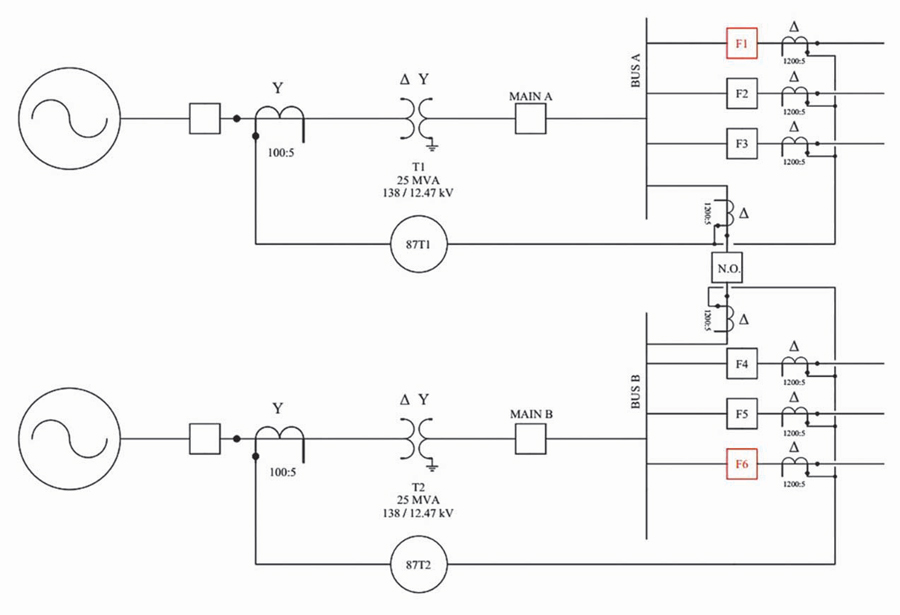
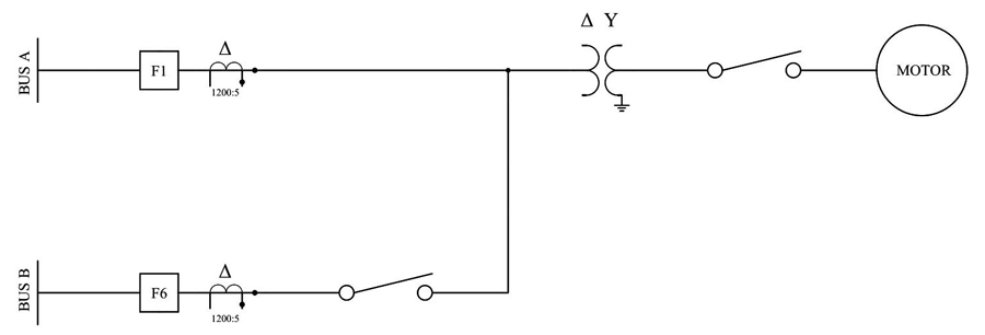
This industrial site feeds several large loads. However, the load of interest in this article is a large motor fed mainly by Feeder F1, which can alternatively be fed by Feeder F6. Figure 1a and Figure 1b show the one-line diagram of the electrical system feeding the industrial site, as well as the configuration of Feeder F1 and Feeder F6 feeding the motor of interest.
87T1 RELAY TRIP
On January 13, 2022, the industrial site experienced a nuisance trip while performing the startup of the motor shown in Figure 1b. The sequence of events is:
A. The motor was running, and it was stopped as part of the site’s procedures.
B. Field personnel attempted a motor start through Feeder F1. Relay 87T1 operated, taking Bus A out of service.
C. Field personnel performed switching to the B-side (Feeder F6). They attempted a motor start through Feeder F6, and the motor started and remained in service.
INVESTIGATION AND TROUBLESHOOTING
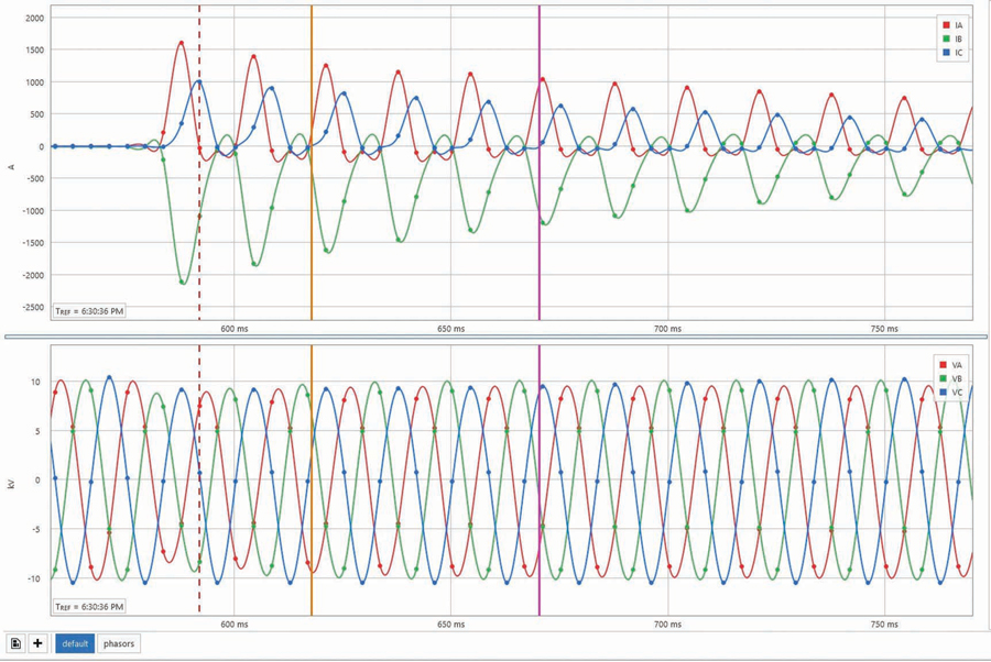
One of our biggest challenges when performing this root-cause investigation was that electromechanical relays do not produce any event data; they only provide a physical flag in the tripped relays. However, the feeder breakers had been upgraded to new microprocessor relays, and because each feeder uses digital feeder protection, they are capable of producing event data. The relay at Feeder F1 only produced a history report, while the relay at Feeder F6 produced history and oscillography reports during the motor startup. The oscillography reports showed inrush current, which is typical during transformer and motor energization, and it was confirmed that no fault was present at Feeder F6. Figure 2 shows the current and voltage waveforms during energization on Feeder F6.
Before the incident, field personnel noticed that utility workers had performed electrical work inside the substation house. Previously, the utility and the industrial site shared the substation house. However, the utility had built its own substation house, upgraded its transmission protection relays, and moved the existing circuits to its new substation house. On January 13, 2022, one of the utility technicians was tasked with cleaning up the old wires at the existing substation house.
The industrial procedures required the motor to be de-energized sometime during the afternoon, and when this motor was re-energized, relay 87T1 tripped. Records show the start attempt on Bus A at around 5:22 pm and the start attempt on Bus B at around 6:57 pm. These attempts were performed late in the day, which means that the electrical issue was introduced into the differential system while the motor was energized and running on Bus A.
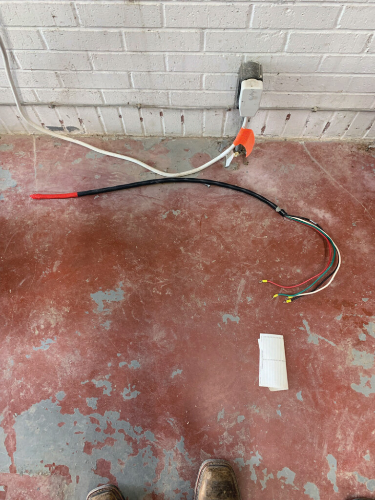
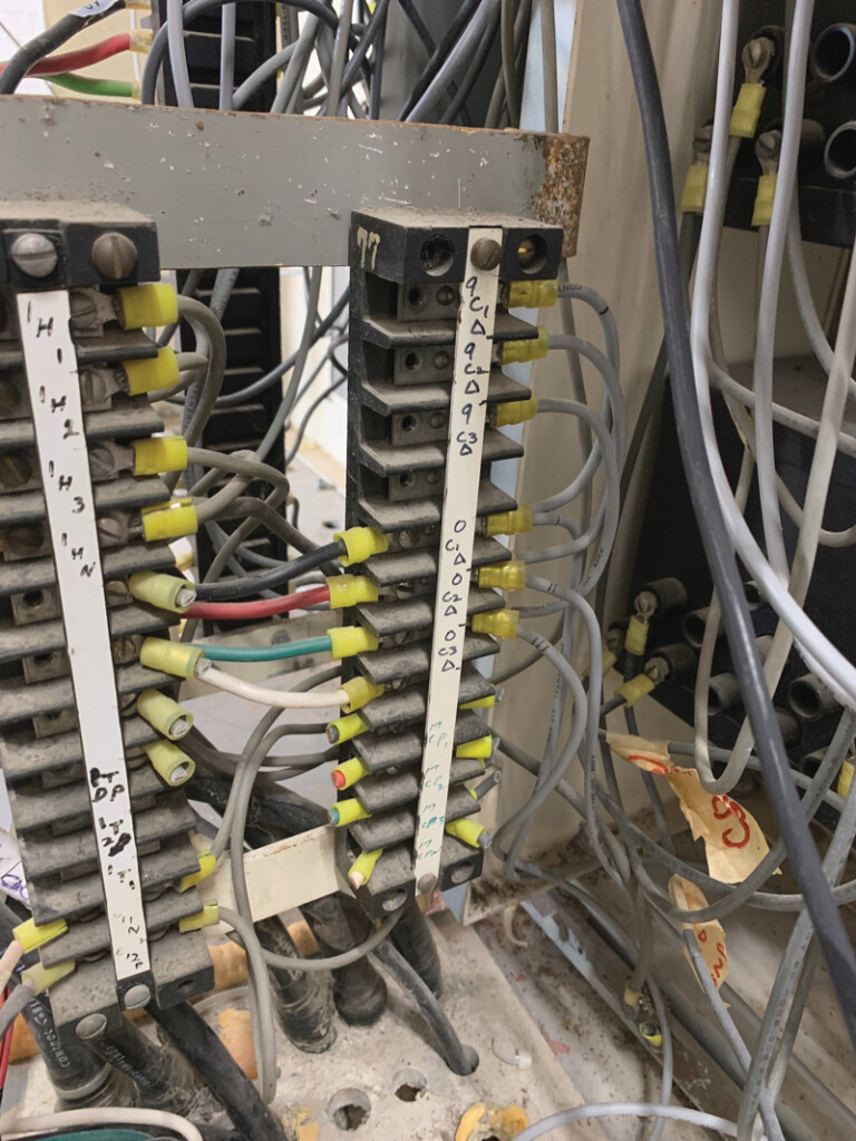
While performing a visual inspection of the 87T1 relay, site personnel noticed that a four-wire bundle had been cut and left behind, as shown in Figure 3a. The bundle had four wires colored red, black, green, and white, which are the colors used for current transformer (CT) circuits. Further inspection of the circuits showed that the bundle belonged to points 9C1∆, 9C2∆, and 9C3∆ (Figure 3b). For the remainder of this article, we will call this the 9∆ bundle.
Two questions arose from this discovery:
- Which circuit did this bundle belong to?
- Why did the removal of this 9∆ bundle cause a misoperation only after the motor was de-energized and re-energized?
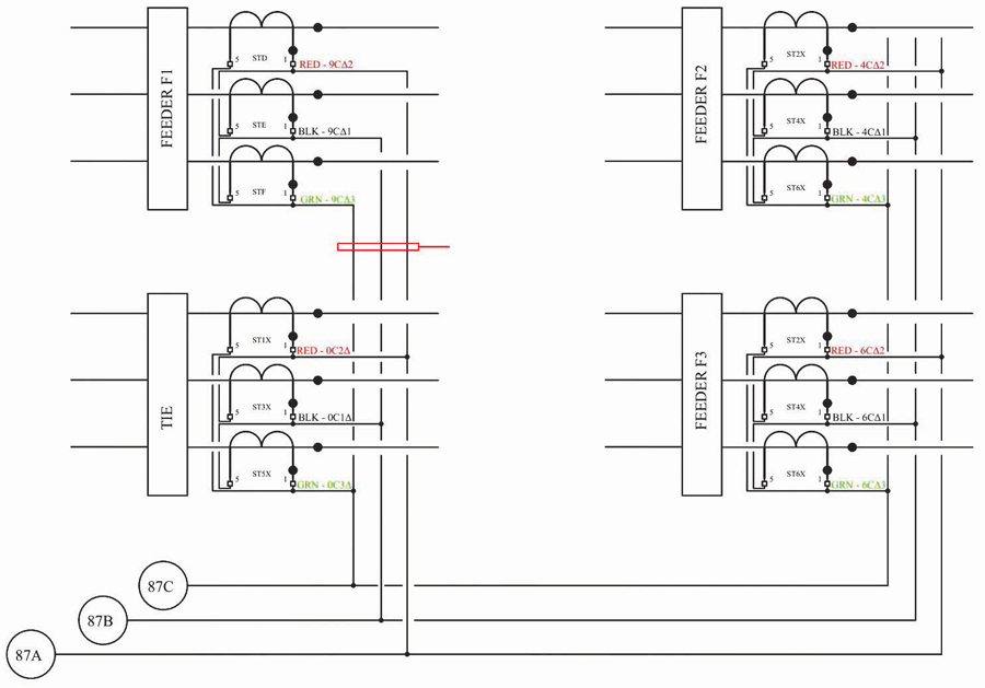
Site personnel examined the three-line diagrams to locate this bundle. The 87T1 relay schematics show that the bundle with wires 9C1∆, 9C2∆, and 9C3∆ is the CT contribution from Feeder F1 into the 87T1 differential relay, as shown in Figure 4. At the time the 9∆ bundle was removed from the system, Feeder F1 was energized and the motor was running; however, the 87T1 relay did not trip at that time.
87T1 MODE OF OPERATION
To understand the operation of the 87T1 relay, it is necessary to know the CT ratio for the primary and secondary sides of the transformer, as well as the relay settings such as the pickup and the tap values. This information is shown in Table 1.

The operation of the 87T1 relay according to the manufacturer’s instruction manual[1] reads:
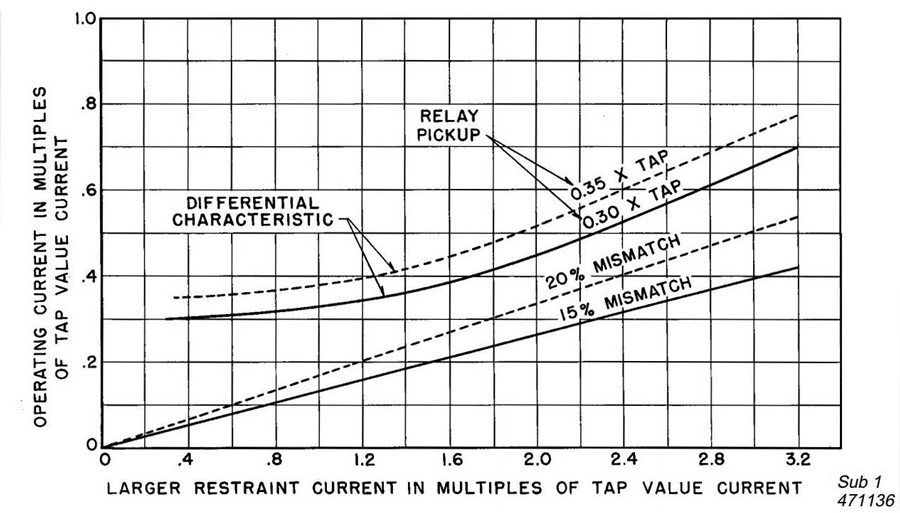
The operating current required to close the contact of the differential unit expressed in percent of restraint current varies with the magnitude of the larger restraint current. To use these curves, divide each restraint current by the appropriate tap and enter the horizontal axis using the larger or largest restraint multiple. Then enter the vertical axis, using the difference of the restraint multiples.
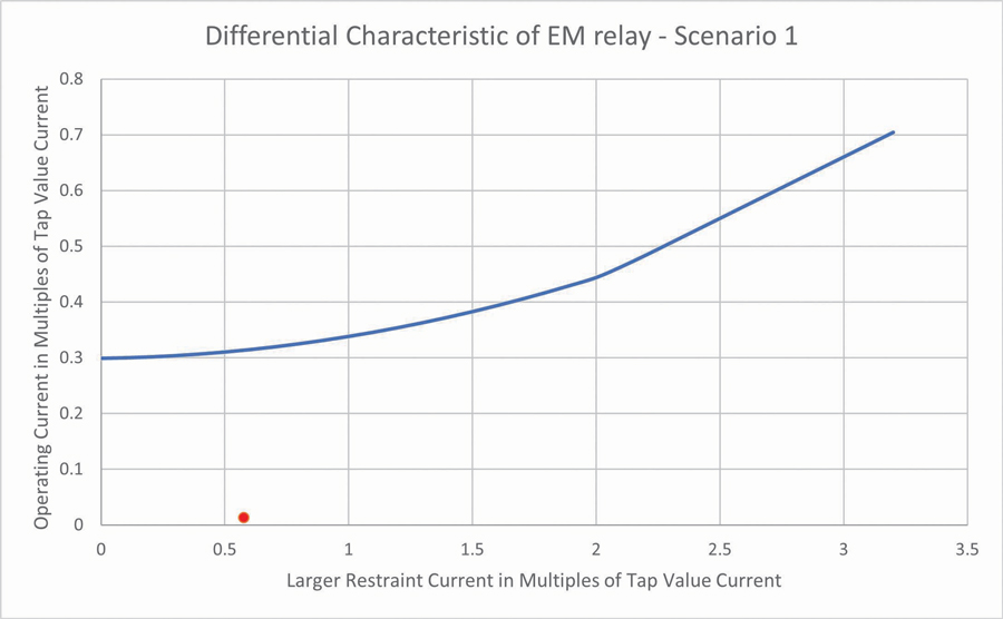
The differential characteristic curve mentioned is shown in Figure 5. The restraint current is plotted on the x-axis, while the operate current is plotted on the y-axis. If the resulting plot is below the curve, the relay will restrain; if the plot is above the curve, the relay will trip. This curve will be used in the scenarios in the next section.
Next, we will analyze four system scenarios.
SCENARIOS
The analysis of the sequence of events on January 13 included the following scenarios:
- Scenario 1. The motor gets energized; all cables are connected properly.
- Scenario 2. The motor is running; all cables are connected properly.
- Scenario 3. The motor is running and the 9∆ cables are removed from the system, effectively removing the Feeder F1 contribution to the 87T1 relay.
- Scenario 4. The motor is stopped and gets re-energized with the 9∆ cables lifted.
SCENARIO 1
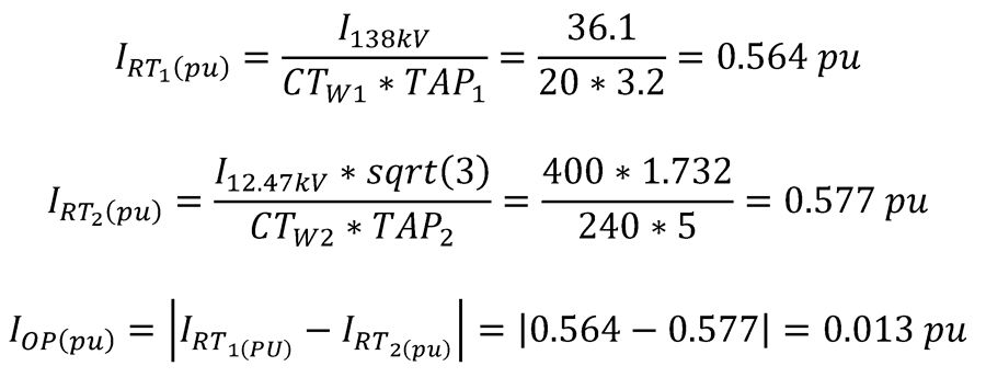
According to field personnel, the motor produces approximately 400 A of inrush current on the 12.47 kV side, which is 36.1 A on the 138 kV side. Assuming that no other load is energized on Bus A, the restraint current is ~0.5 pu on each side of the transformer, while the operate current is very close to 0.
Note: Because the CTs on the secondary side are delta-connected, it is necessary to introduce a multiple of sqrt(3) on Restraint Current 2. Figure 6 shows the largest restraint and operate current plotted on the differential characteristic used by the 87T1 relay in Scenario 1.
SCENARIO 2
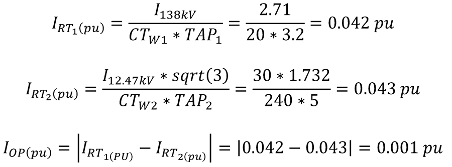
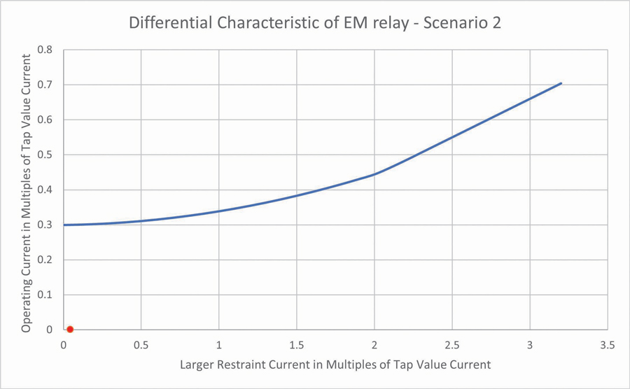
According to field personnel, the motor has a full-load amperage (FLA) value of approximately 30 A at the 12.47 kV level, which is 2.7 A on the 138 kV side. Assuming that no other load is energized on Bus A, the restraint current is ~0.04 pu on each side of the transformer, while the operate current is very close to 0. Figure 7 shows the differential characteristic for Scenario 2.
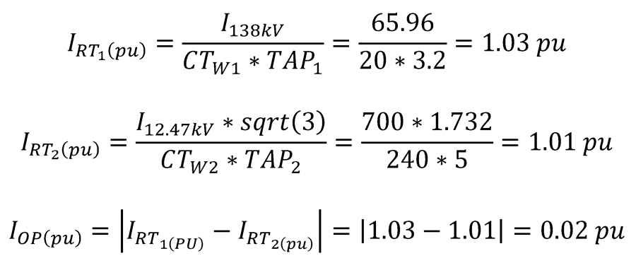
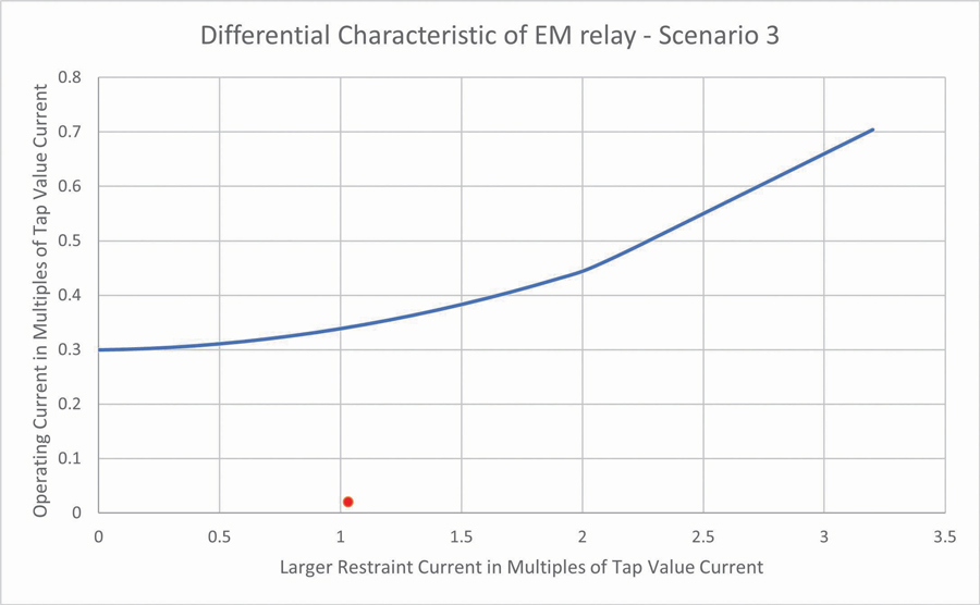
SCENARIO 3
Scenario 3 is a critical scenario in which a safety concern is introduced due to the risk of removing a CT circuit while the system is energized, effectively opening the CT. In the next section, we will cover the safety concern; however, the 87T1 relay did not operate during this circuit removal. According to field personnel, prior to the removal, Bus A was carrying approximately 730 A. After the cables were removed, the 87T1 relay lost its motor contribution (30 A). Figure 8 shows that, even though the contribution from primary and secondary sides was not equal due to the amount of load in the system, the operate current increased only slightly.
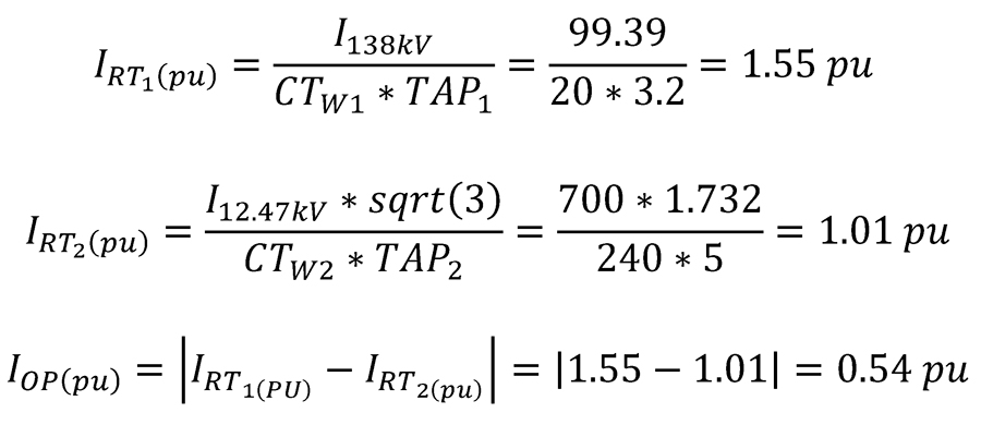
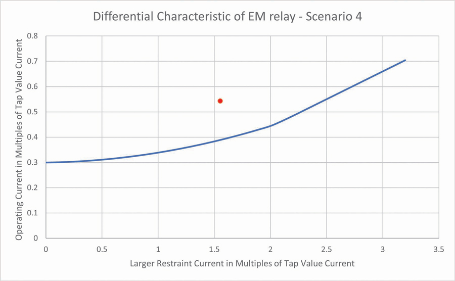
SCENARIO 4
The motor was stopped (as required by the industrial procedures) and re-energized later the same day. This time, the 87T1 relay operated and tripped, taking Bus A out of service. During energization, the contribution to 87T1 from the primary side of the transformer would be 400 A larger at 12.47 kV due to the motor’s inrush current, and since the system was carrying 700 A already, the total contribution would be 1,100 A at 12.47 kV, or 99.39 A at 138 kV. Figure 9 shows that the resulting plot is above the curve, and therefore the relay sends a trip signal.
SAFETY CONCERN
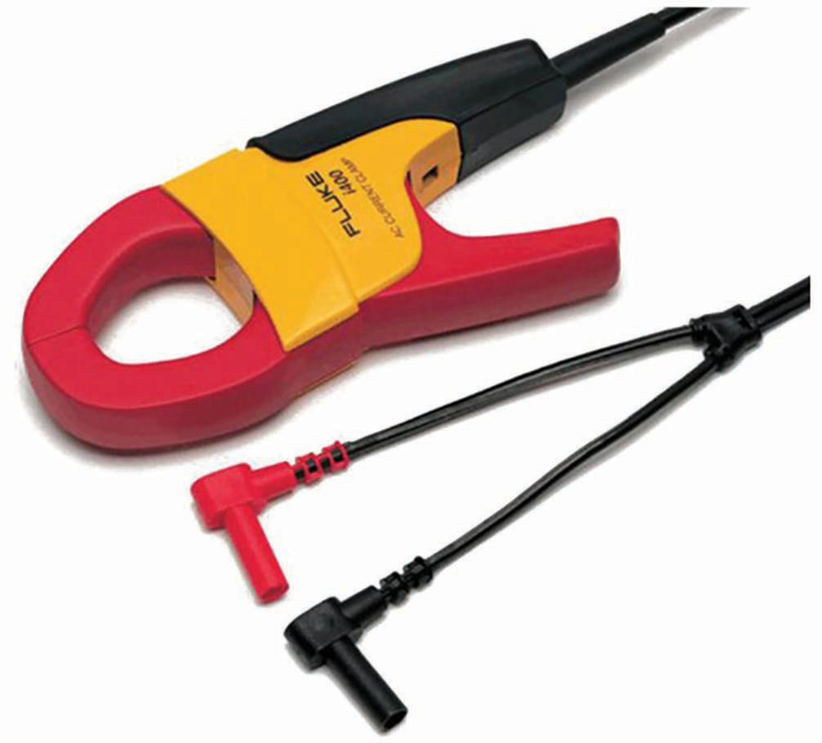
Energizing a CT that is open circuited (on the secondary side), typically referred as an open CT, represents a very critical safety concern. As explained in detail in D. Costello,[3] an open CT will create a condition of extreme saturation and develop extremely-high excitation voltage. This will damage equipment such as CTs, relays, and wiring insulation, and it will expose electrical workers to severe injury, such as loss of limb or death. Verification of the lack of current flowing through a CT wire can be easily performed using an amp clamp meter, such as the one shown in Figure 10. In this case, the Feeder F1 current transformers for the 87T1 relay were damaged and replaced at a subsequent outage.
CONCLUSION
The process of replacing electrical equipment at a substation requires full knowledge of the electrical circuits, which is typically achieved by proper study of the site schematics. Performing modifications while the substation is energized is a dangerous task, and removing the incorrect (energized) wire can lead to a nuisance trip, which could translate to high economic cost and environmental impact, as well as posing a safety risk that could lead to severely injury or death to electrical personnel.
REFERENCES
[1] ABB, Inc. Type HU and HU-1 Transformer Differentials Relays Instruction Manual, 1999. [2] A. Rangel. “Electromechanical Differential Relays Misoperation and Investigation,” 74th Annual Conference for Protective Relay Engineers, College Station, TX, March 2021. DOI: 10.1109/CPRE48231.2021.9429717. [3] D. Costello. “Open-Circuited CT Misoperation and Investigation,” 67th Annual Conference for Protective Relay Engineers, College Station, TX, April 2014. DOI: 10.1109/CPRE.2014.6799015.
Alex Rangel is a Protection and Controls Engineer for Saber Power Services, LLC. He is a NETA Level 4 Technician. Alex has been an IEEE member for 11 years and a registered Professional Engineer (PE) in the state of Texas since 2014. He holds a BS in electrical engineering and an MS in engineering from the University of Texas at Austin.