The stator core of a rotating machine is composed of multiple stacked layers to minimize eddy current losses. A short between two or more layers leads to higher local eddy currents. This in turn can lead to local hot spots, which in a worst-case scenario can cause a partial core melt and eventually damage the machine. A ring flux (or full flux) measurement, where the machine is excited at rated flux and potential hot spots are detected using a thermographic camera, demands a high amount of power. Furthermore, the setup is time- and resource-consuming.
Stray flux measurement (also known as electromagnetic imperfection measurement) is a reliable alternative that uses a portable power source and a measurement device that can be energized via an ordinary power plug. In addition to conventional measurement at rated frequency, using a power source that allows the stator core to be excited at higher frequencies (up to 400 Hz) can lead to improved sensitivity in certain conditions. Injection at different frequencies allows faults to be detected deeper in the core and can be compared to ring flux measurement.
ASSESSING CONDITION
Throughout a rotating machine’s lifetime, several conditions are undesirable for optimal performance. Such conditions might be discovered during a visual inspection or specific off-line or on-line tests. Considering that the core laminations that make up the stator core are shorted together at the back of the core by building bolts or keybars, it is vital for the rest of the lamination surfaces to be electrically insulated from adjacent laminations. This condition might not be too serious for a single short between two laminations, but several shorts along adjacent laminations in addition to the building bolts or keybars would form a loop, and the induced circulating currents could be large enough to cause excessive local heating. If this heat cannot be sufficiently dissipated by local cooling, more inter-laminar failures would follow. If such an abnormal condition is not detected and repaired at an initial stage, the fault condition could lead to the melting of the core laminations and eventually total machine failure in the worst-case scenario.
Several mechanical and electrical tests and methods are available for assessing stator core tightness and stator core lamination insulation. These test methods usually require that the rotating machine be taken out of service and the rotor pulled out. The condition of the interlaminar insulation in the stator core can be assessed using electromagnetic test methods.
This article describes the benefits of performing a low flux measurement (ELCID) test to assess the condition of stator cores. Some of the advantages of this method include low power requirements and short setup time. This method has the additional benefit of producing a permanent record of the condition of the interlaminar core insulation, which can be used as a benchmark for further comparisons.
For the benefit of readers, a short description of stator core construction and an introduction to the basic principles of performing a low flux measurement are first explained. Investigations are then detailed to show the influence of the frequency of the induced flux on the test results. The results of a low-flux measurement and a full flux measurement are compared.
STATOR CORE CONSTRUCTION
The primary functions of the stator core are to hold the stator windings in place and to provide a low-reluctance path to the magnetic flux. The core must handle magnetic field flux densities in the stator teeth and in the core back or yoke area.

The stator core is manufactured of thin laminations or sheets of electrical-grade (electrical steel sheets), 3%–4% silicon or grain-oriented, and 0.355 mm or 0.483 mm thick steel, such as the single lamination shown in Figure 1. They are segmented, meaning that from 10 to 24 laminates (depending on the machine design) are laid side by side to form a full 360-degree ring layer. Each of these layers is staggered relative to the locations of adjacent layers above and below by the butted radial edges of the adjacent laminates in each ring layer.
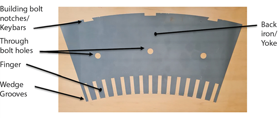
Usually, the stator core contains thousands or tens of thousands of core laminations that must be held tightly together, especially when the machine is laid sideways during installation and operation. To keep the laminated ring segments in line with each successive layer, they are fitted onto keybars in a stator frame structure. It is common for the laminations to be electrically connected at their outside edges where they are clamped to the building bars via keybars. Additionally, they are clamped axially to consolidate the core as a solid and stiff mass.
Two basic methods are used to achieve axial clamping force in larger machines:
- The most common is to use the keybar structure, on which the core is mounted by dovetail slots in the core laminates at the core back, in conjunction with a large full-ring pressing plate at each end of the stator.
- The other is to additionally use through-bolts installed through holes in the core yoke area that extend the full axial length of the stator core and through the pressing plate.
The laminations are usually welded to the stator frame in smaller machines, such as the one in the photo. In this case, welding provides good electrical contact. Therefore, a short between two or more of the laminations will cause a circulating current, resulting in a local hotspot.
Each lamination is insulated on both sides with an organic or inorganic compound of very thin dimension. The purpose of the interlaminar insulation is to confine any induced eddy currents by reducing the area where it can be induced to a minimum (Figure 2). This reduces the current magnitude and results in an overall reduction of eddy-current loss and associated temperature rise.

Slots are provided in the stator core for installation of the stator winding. Core material is removed to accommodate the winding; hence, the tooth flux densities are very high in this area. This affects the generated losses and heating in the core and the winding, which the machine cooling must dissipate. The portion of the core below the bottom of the winding slots is called the yoke or core back area.
BASICS OF LOW FLUX MEASUREMENTS
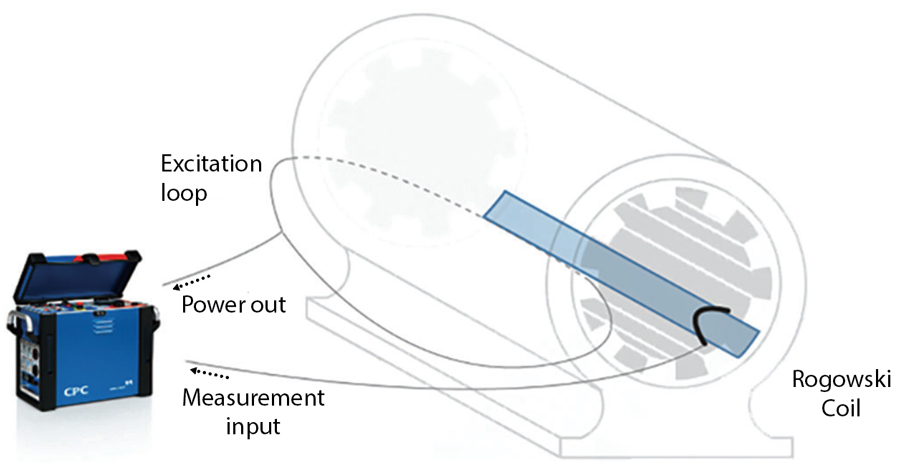
The purpose of the low flux test is to assess the interlaminar insulation condition of a rotating machine’s stator. This method uses two main elements: an excitation winding and a Chattock potentiometer sensor. The excitation winding is wound around the core. Its function is to induce a flux inside the core with typically 4% of operating flux (Figure 3). The induced fault currents are measured by sensing the magnetic field using the Chattock potentiometer sensor.
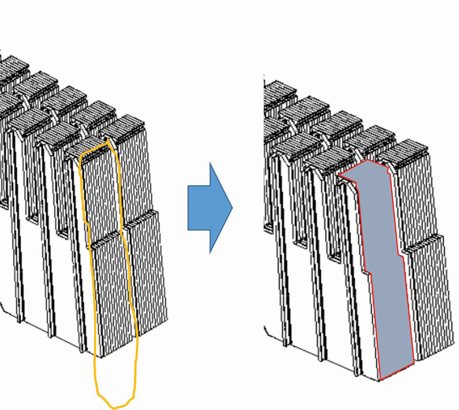
As previously mentioned, it is common for the laminations in the stator cores of rotating machines to be electrically connected only at their outside edges. Therefore, an additional electrical connection (weak spot) between two or more laminations at a point other than their outside edges will produce a circuit loop between the weak spot and the clamped point on the back of the iron core, inducing circulating current (Figure 4).

The low flux test method essentially searches for weak spots in the stator core. These weak spots can arise when the insulation between two or more consecutive laminations in the stator core has broken down or is defective. An induced current can flow in the circuit loop established by the shorted laminations and the keybars or the welding connections at the frame as shown in Figure 5.

The fault current can be detected as a higher stray flux by a Chattock or Rogowski coil scanning the stator surface as shown in Figure 6.[3] Slots are scanned one by one by the measuring coil. The coil readings are correlated to a certain position within the stator core and are usually visualized using a heat map or by displaying all measured currents on a single graph. A common value at which locations should be investigated is 100 mA of the quadrature current when measurements are performed at 4% of rated flux and rated frequency.[1, 2] Later in this article, Figure 13 shows a graph with several traces superimposed, and Figure 14 provides an example of a heat map.

As the measurement coil width and the number of turns of the sensor remain the same for each measurement, a calibration should be obtained prior to each measurement.
Different slots are sequentially scanned by different measurements. The coil span is between the teeth of one slot to the next slot to ensure a certain overlapping area.
EXPERIMENTAL SETUP
Investigations regarding reproducibility and measurements with various frequencies have been performed on a small, decommissioned hydro generator with a rated voltage of 6.4 kV and 156 slots. The stator winding is a coil winding with two turns per coil. All other experiments described in the sections on Detecting Faults Deeper in the Stator Core and Comparison to Ring Flux Measurements have been performed on different machines. The setup is explained in the corresponding sections.
For better visibility into the effect of various excitation frequencies on reproducibility, the experiments on the small hydro generator have been carried out by measuring over an artificial fault. A stator segment is shorted by a wire as shown in Figure 7. The reason for this modification is that it is easier to use the wire over two ventilation ducts rather than damaging the stator core.
In the Reproducibility section, a different artificial fault was used than in the section on Measuring With Different Frequencies.
REPRODUCIBILITY
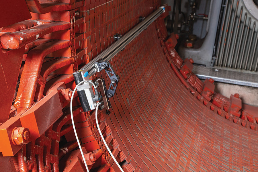
The measurement device in this investigation consists of a semiautomatic movement of the Chattock sensor on a rail. The sensor itself travels over the stator surface at 2 mm to 3 mm, which ensures a sensitive measurement. The setup is shown in the photo.
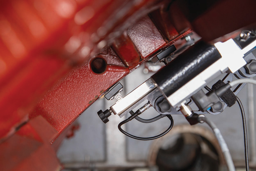
To ensure that the often-used interpretation limit is not influenced by the measurement setup, investigations on reproducibility have been performed. It becomes even more important to estimate the criticality of existing potential weak spots as the user wants to have a way to trend the results over time.

The first comparison in Figure 8 shows two measurements on the same slot with a fault without changing any setting.

As the high reproducibility is not surprising, in the next comparison in Figure 9 the mechanical setup and adjustment were performed each time at the beginning of each measurement. In this case, the same healthy slot was scanned, so no fault was implemented in these measurements. Each measurement trace was recorded after redoing the mechanical setup each time at the beginning of each measurement. The spread of the results is higher than in Figure 10, but it is still very low and does not present a hindrance to reliable measurement.

MEASURING WITH DIFFERENT FREQUENCIES
The effect of the measurement with higher frequencies is explained with two comparison measurements at 50 Hz and 400 Hz. Both measurements were executed on the identical slot with the same artificial fault. No changes or modifications were made between the different measurements; the only changes made were to the excitation parameters. The measurement was performed on the small hydro generator with 24 excitation windings described in the Experimental Setup section.
As known, flux is inversely proportional to frequency but behaves proportionally to the voltage. To compare two measurements with different frequencies, the excitation voltage was kept the same in the first experiment. Consequently, the flux for the 8-times-higher frequency measurement decreased by a factor of 8.
However, in the second attempt, flux was kept the same for both measurements. Therefore, the excitation voltage had to be adapted accordingly. Table 1 and Table 2 offer an overview of the two settings.


If measured with 0,5% of rated flux at 400 Hz, the highest peak at the defect has an absolute amplitude value of around 400 mA, while at 4% and 50 Hz, the peak reaches around 650 mA (Figure 10). Although this is much lower, flux was decreased by a factor of 8!
Furthermore, we also see lower fluctuation around the zero line of the 400 Hz measurement when looking at the healthy section of the slot (Figure 11).
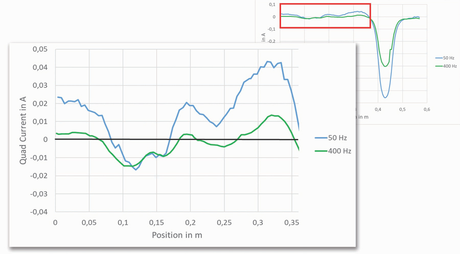
As already assumed from the first experiment, when keeping flux equal for both frequencies, the picture changes completely, as displayed in Figure 12. In this case, the amplitude of the 400 Hz measurement is much higher than the 50 Hz measurement. When comparing this with the measurement in Figure 10, please be aware of the different scaling on the vertical axis.

An absolute limit for frequencies different than the rated frequency does not exist and might be the topic of future investigations. Although no limits exist, measurement with higher frequencies could be an attractive approach. As the stray flux measurement is also a comparative method, it seems as though measurement spikes on fault locations are clearly visible with higher frequencies.
DETECTION OF FAULTS DEEPER IN THE STATOR CORE
Faults in the lamination insulation can be detected even if they are located deeper within the stator core. This is demonstrated in a practical use case, where a motor was in a repair shop due to a phase-to-ground fault in the machine. The protection worked well in this case and tripped immediately; therefore, the damage in the machine due to the fault was comparably small and not visible from outside. An endoscopic inspection of each ventilation duct was able to localize the issue. From this investigation, it was known that the fault is located on the bottom side of a lower bar. The project leader responsible for the repair wanted to know whether the stator core was affected and needed to be repaired as well. The measurement results depicted in Figure 13 show a clear peak over 100 mA at around 800 mm of the stator core.

The operator was convinced that the problem in the stator core was already present before the maintenance work, and the damage did not happen during the change of the coil.
COMPARISON TO RING FLUX MEASUREMENTS
To compare the stray flux measurement and the situation during machine operation, a comparison measurement was performed. The test machine was completely renewed so it was possible to implement faults and compare the measurement with the full flux test and a thermographic camera.
These photos show two ways of implementing these faults.


Depending on the modification technique, not every spot shows a significant increase in temperature during the full flux test or in the stray flux measurement. Two modifications showed a temperature raise of >10°C, which is considered critical.[1] These locations could also be reliably detected with the stray flux measurement and an amplitude higher than 100 mA. The heat map with the results of the entire stator as well as the thermographic picture of the two critical spots is displayed in Figure 14. The other spots showed less temperature increase compared to the surroundings. They were also visible in the stray flux measurement, as locations with higher stray flux remained below the limit of 100 mA.

CONCLUSION
The stray flux measurement is a reliable method to detect weak spots in the interlamination insulation of stator cores.
The repeatability between tests was successfully demonstrated, and a comparison between a full flux measurement showed similar results. In addition, when using a frequency variable power source, increased frequency could lead to improved sensitivity on some defects for specific circumstances.
Equipment portability and easy setup make the solution interesting for performing on-site measurements as well as workshop applications.
REFERENCES
[1] IEEE Std 56-2016, IEEE Guide for Insulation Maintenance of Electric Machines, Annex D (informative), September 2016. [2] Cigre. Brochure 257, EL CID (Electromagnetic — Core Imperfection Detector) Testing of Large Steam-Turbine Driven Generators. Working Group A1.01.06, October 2004. [3] Bertenshaw, David Ronald. “Stator Core Interlamination Faults and Their Detection by Electromagnetic Means.” PhD Thesis, University of Manchester, Faculty of Engineering and Physical Sciences, 2014.
Fabian Öettl is a Product Manager at OMICRON Technologies Italia GmbH. In his role, he is responsible for rotating machine testing and diagnostic equipment. Before he joined OMICRON, Fabian worked in the R&D department of a manufacturer of large generators as a high-voltage insulation specialist. He has written many scientific and technical papers and contributes to various working groups of Cigre and IEC. He received his MSc from Graz University of Technology in 2011.

Mathieu Lachance joined OMICRON electronics Canada in 2019 and presently holds the position of Regional Application Specialist for partial discharges and rotating machines for North America. Before joining OMICRON, Mathieu worked as a test engineer in the fields of partial discharges and high voltage. His current interests are partial discharge testing, dielectric frequency response analysis, and condition assessment of high-voltage and medium-voltage equipment. He received a BS in electrical engineering from Université Laval and currently pursues his graduate education at École de technologie supérieure, with a focus on the use of dielectric frequency response analysis applied to stator winding insulation systems.
