
Every current interruption involves an arc burning between the contacts of a circuit breaker (CB). The produced arc energy and associated pressure increase is used in gas circuit breakers to cool the arc region leading to current interruption.
The same arc energy causes wear that can be separated into two main phenomena:
• Nozzle ablation, which affects pressure build up, flow characteristics, and interrupting efficiency.
• Contact erosion, which reduces the time interval available for the current commutation and changes the contact surface, affecting the dielectric characteristic of the interrupter.
The majority of SF6 dissociated by the arc during the interruption process recombines after cooling down, leading to almost no SF6 consumption. However, this is not the case for circuit breakers using the environmentally friendly alternatives recently presented on the market. These alternative gas mixtures use CO2 as carrier gas in percentages above 90%. Two types of fluoro-molecules are marketed:
• Fluoroketones (FK) offer a very low global warming potential (GWP) yet are limited to indoor operational temperatures.
• Fluoronitriles (FN) offer a negligible GWP and have no limitations on minimum operational temperatures.
These new quenching media offer significantly lower environmental impact but have the characteristic of not recombining after being decomposed, according to Seeger et al. This implies a medium that is consumed and thus introduces an additional wearing factor along the CB lifetime. The consumption, or irreversible decomposition, of these gases is a function of cumulated interrupted current or arc energy and needs to be estimated. Comparing it with the degradation pattern for nozzle ablation and contact erosion, it can be assessed whether the irreversible dissociation can or cannot affect the arc quenching and electric withstand capability of the circuit breaker.
Estimations are offered using fluoroketones as example. The same type of assessment can be done for fluoronitriles. It is shown that, depending on the CB design and fluoro-molecule content, the end of life of a next-generation switchgear could go from traditional effects such as nozzle ablation and contact erosion to new effects like gas quality-dependent performance reduction. In practice, the decomposition of the insulation and quenching medium turns relevant only when it becomes the circuit breaker functionality-limiting factor instead of nozzle ablation and/or contact erosion. More details of these competing wearing mechanisms are given in the next section.
INTERRUPTING MEANS
The vast majority of high-voltage circuit breakers currently installed use SF6 as the quenching and insulating medium. Although every manufacturer developed its own designs, all are based on the same interrupting principle of cooling the arc region between the contacts to clear the current at the naturally occurring zero crossings. To hit this target, the current is commuted from the main contact system, which is meant to carry the nominal current in close position, to the arcing contact system, which is meant for the interruption. Arcing contacts, typically made of copper-tungsten (WCu), have the best available temperature resistance.
During arc burning, a nozzle system, typically made of PTFE, channels the gas towards the arc region, cooling it down and interrupting the current at a zero crossing. The energy dissipated by the arc at each interruption can easily reach hundreds of kJ for arcing times that can vary between 5ms and 25ms. This high amount of energy causes ablation of the nozzles and erosion of the contacts. The sublimated PTFE nozzle material contributes to the pressure build-up needed for clearing the current. The consequent nozzle profile modification impacts fluid-dynamic efficiency and interrupter-clearing capability.
Changes in the geometry of the arcing contacts caused by arc erosion impact the time interval for current commutation as well as the dielectric characteristic of the interrupter. In traditional circuit breakers, nozzle ablation and contact erosion are the two main mechanisms driving CB wear. The two mechanisms impact different aspects of interrupter functionality. Depending on the current interrupting history, one or the other reaches its limit, dictating the electrical endurance state of the circuit breaker, as reported by Gariboldi and Corliss.
The great majority of SF6 decomposed in the arc during the interruption recombines again after current zero. Only a limited percentage reacts with the nozzles and contact materials producing gaseous and solid by-products. This consumption of SF6 for every interruption is negligible in comparison to the other two wear effects.
Circuit breakers using SF6 alternative gases have been recently presented on the market. These new gas mixtures offer significantly lower environmental burden but have the characteristic of not recombining after decomposition. This implies a medium that is consumed and thus introduces an additional wearing factor along the CB lifetime
INTERRUPTION EFFECTS
During every current switching in a high-voltage circuit breaker, an arc burns between the arcing contacts. The arc energy is given in Equation (1) and can easily reach hundreds of kJ for typical arcing times between 5ms and 25ms (Figure 1).
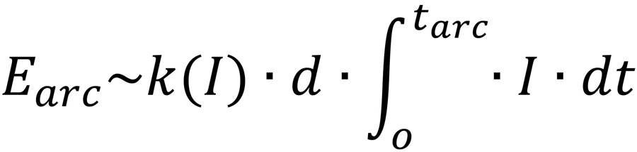
Equation 1
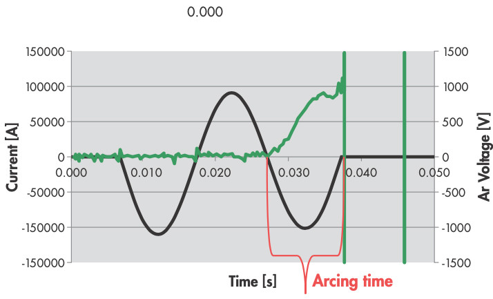
Figure 1: Current and Arc Voltage during the Interruption Process
Material Sublimation
The arc energy causes material sublimation in nozzles and contacts. The resulting geometrical changes constitute the wear of the interrupting chamber known as nozzle ablation and contact erosion (Figure 2).
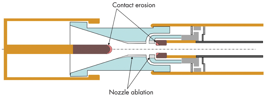
Figure 2: Interrupting chamber wear caused by arc energy results in ablation of the nozzles and erosion of arcing contacts plug and tulip.
Nozzle Ablation
Ablation of the nozzles is caused by arc radiation and the hot gas flow during interruption (Figure 3). This is a function of the arc energy dissipated during the interruption process.
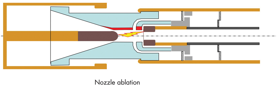
Figure 3: The radiated energy from the arc causes sublimation of PTFE material from the nozzles shown by the red area only on one side for comparison with the original profile.
The specific ablation — the amount of sublimated PTFE per kJ of arc energy — is a function of the percentage of interrupted current as shown in Figure 4.
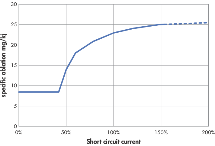
Figure 4: The radiated energy from the arc causes sublimation of PTFE material from the nozzles shown by the red area only on one side for comparison with the original profile.
The diametrical widening of the nozzle system from one shot to the next causes increases in the distance from the arc to the nozzle wall; this results in lower energy adsorption and thus less PTFE vapour. Lower adsorbed energy together with a larger gas flow cross-section reduces pressure build-up in the chamber and by this arc cooling. This results in reduced clearing capability that primarily affects switching cases like short line fault (SLF), where maximum cooling power is required to turn the quenching medium from conductive into insulating in the arcing zone after current zero. In practice, getting an accurate degradation dependency is quite difficult. Typically, a logarithmic diagram giving the number of operations as a function of interrupted current can be found (Figure 5).
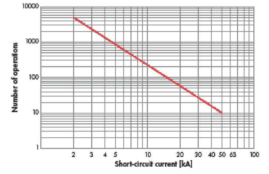
Figure 5: Typical Logarithmic Diagram Showing Maximum Allowed Number of Operations as Function of Interrupted Current
The actual performance limit can change with the arcing time at interruption as well with the fault typology. For example, a CB not connected to an overhead line and therefore not facing short line-fault conditions is typically less sensitive to nozzle ablation.
Contact Erosion
Erosion of the arcing contacts is the other main wear mechanism that occurs during current interruption. Tungsten-copper is typically used as the arcing material. Its erosion causes changes in the geometry of plug and tulip mainly at the tips (Figure 6).
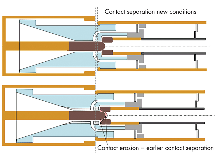
Figure 6: Contact Erosion Causing Earlier Separation of Arcing Contact
The shorter plug and wider tulip result in earlier contact separation that reduces the time available for the current commutation. If the arcing contacts begin parting before the current commutation is complete, an arc will burn between the main contacts, likely resulting in a catastrophic failure. This is not the only effect of contact erosion. Depending on their specific design, eroded contact profiles can result in higher dielectric stress that reduces switching performance, e.g., in capacitive switching test duties. The reduction of commutation time, however, is the most onerous consequence of arcing contact erosion.
Commutation time depends on the current amplitude and the resistance and mutual inductance of the main and arcing contact. Grid conditions and fault typology do not play any role. A sound reference for commutation time for high-voltage circuit breakers is between 1ms and 2ms. In Kassubek, et al, the mean specific erosion rate of arcing contacts as a function of the current density is indicated as a non-linear proportional function ranging from ~2mg/As (amperes*seconds) up to ~12mg/As. Its characteristic differentiates between an early region where metal vapour is produced to a later region where droplets plus vapour are generated. This suggests that in order to determine not only the geometry but also the roughness conditions of the arcing contacts, the correct current density at specific arcing times must be considered.
Wear Estimation
Both nozzle ablation and contact erosion are a function of arc energy, yet not necessarily in the same way. The combined wear of both effects is very often estimated by means of Equation (2):
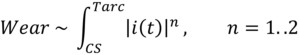
where CS denotes the physical contact separation of the arcing contacts and an arc burning between these.
The actual end of life is reached when one of the wear mechanisms has a dominant effect over the circuit breaker’s selected performance indicator. This depends on the design as well as on the switching conditions. For example, a line circuit breaker will be more affected by nozzle ablation than one connected to a transformer facing terminal faults only.
SF6 AS QUENCHING AND INSULATING MEDIUM
The vast majority of high-voltage circuit breakers use SF6 as the quenching and insulating medium. During the interruption process, when the arc is burning between contacts, SF6 is decomposed in the plasma into sulphur and fluorine atoms.
Once the gas has cooled down after interruption. the majority of S and F recombine forming SF6 again. Seeger, et al, discuss the by-products of SF6 after electrical discharges. Although commonly accepted, the recombination of SF6 after arcing does not occur to its 100% initial state. The presence of water in the switchgear contributes to the creation of by-products such as HF and SOF2, among others. SF6 decomposition does not amount to more than a couple of percent, and given its outstanding insulating and arc quenching capabilities, has never been a limiting factor in switchgear functionality. Toxicity-wise, some considerations might be necessary to guarantee personnel safety; hence, measurement of the generated species might prove useful.
NEW SF6 ALTERNATIVE GASES
Seeger et al. evaluated state-of-the-art alternatives to SF6 for insulation and switching. From these, three gas mixtures are being investigated by different switchgear manufacturers (Figure 7):
• Pure CO2
• CO2 + fluoroketones (C5-FK)
• CO2 + fluoronitriles (C4-FN).
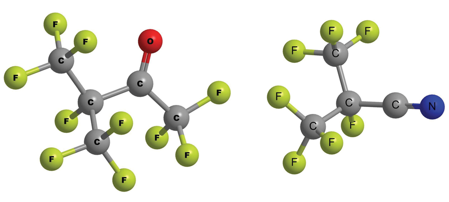
Figure 7: C5-Fluoroketone (left) and C4-Fluoronitrile (right) Commercially Available as Novec 5510 and Novec 4710 Respectively from 3M Deutschland
The use of CO2 in all the alternatives is a commonality given its superior arc-quenching capabilities, still less than SF6 but above other natural, non-contaminant, naturally occurring gases, as reported in Uchii, et al.
In some cases, oxygen (O2) is used to avoid toxic by-products and soot after switching.
This implies a consumption mechanism that might be objective to monitoring. The by-products of CO2 and the consumption of the fluoro-molecules are to be assessed. These start to decompose at temperatures of around 600°C, which is readily achievable in most switching cases. Unlike SF6, once these molecules are decomposed, they do not recombine and smaller molecules are formed, report Seeger et al. Reference to the by-products of fluoroketones is given in Mantilla, et al. Besides the safety and toxicity aspects, also the operational aspect needs to be considered. On the one hand, the impact of the by-products on the switchgear component materials needs close follow-up. On the other hand, fluor-molecules are present in the alternative mixtures in molar volumes of less than 10%. Hence, every percent in the reduction of these by arcing, decay, liquefaction, or leakage can impact the proper functioning of the switchgear. In Mantilla, et al, a consumption rate of the C5-FK of ~0.5 mol per Mega Joule is given. Under realistic circumstances, the decomposition of the SF6-alternatives might become the limiting parameter in switchgear lifetime depending on its design.
EXAMPLE
In Figure 8, nozzle ablation (left y-axis) and FK consumption (right y-axis) is plotted against the energy (kJ), while contact erosion (left y-axis) is plotted against charge (A*s). An ablation rate for nozzle material of 20mg/kJ is used, while an erosion rate of 7mg/As is assigned for arcing contact material. The FK consumption rate is taken as 0.5mol/MJ. The x-axis represents the cumulated energy and charge with realistic values for high voltage circuit breakers.
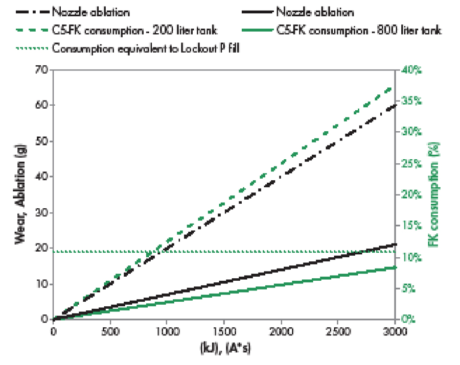
Figure 8: Diagram showing nozzle ablation, contact erosion, and FK consumption for large (800-litre) and small (200-litre) tank volumes. The horizontal pointed line shows the 11% FK consumption — content equivalent to lock-out conditions.
Ablation, erosion, and consumption values are arbitrarily calculated up to a cumulated 3MJ of energy or 3000A*s of charge, which are the typical maximum values covering a whole short-circuit test duty cycle with 100% of the current (T100s). This is taken as the limiting value of ablation and erosion for nozzles and contacts, respectively.
For nozzles, this value could signify so much change in the inner geometry that, for example, short line fault (SLF) interruption is no longer possible. For arcing contacts, this accumulated charge could imply the reduction of overlap leading to a decrease of commutation time to unsafe values, e.g., less than 1ms. In the case of FK consumption, two trends are given: the bottom solid line, where FK consumption after 3MJ is only 8%, and the top dashed line where the FK consumption amounts to 38% of its initial value.
These values represent 800-litre and 200-litre tanks. Ignoring other mechanisms by which the mol content of fluoro-molecules inside the switchgear could be reduced (e.g., leakage, liquefaction, decay, reactivity with CB materials, etc.) for simplicity, the ideal gas law explains the differing trends, with the free gas volume of the switchgear (V) and the partial pressure of the fluoro-molecules (P) as variables.
The two cases can be compared considering 11% as the attention level of consumption, which corresponds to the difference between filling and lock-out conditions (type test). In the 800-litre-tank breaker, FK consumption stays always below 11%, ensuring the FK amount is higher than the type test conditions. For the 200-litre-tank breaker, FK consumption goes beyond 11% reaching 38%, which could impact breaker switching capability. Depending on the CB design and fluoro-molecule content, the end of life of a next-generation switchgear could go from traditional effects such as nozzle ablation and contact erosion to new effects like gas-quality-dependent performance reduction.
CONCLUSION
A new wear process is introduced with the use of alternative SF6 gases. The long molecule chains do not allow a recombination after every interruption process. The gas consumption competes with the traditional wear processes of SF6 breakers. A case-by-case evaluation can highlight whether this effect is critical or not.
 Nicola Garaboldi is a Technical Application Specialist and Director of Field Service, EMEA at Qualitrol LCC. He previously spent 23 years at ABB developing high-voltage interrupters and surge arrestors. Nicola is a convener of CIGRE WG A3.43 and a member of WG A3.39, A3.32, and A3.19. He is a member of IEC MT 40 and PT 50.
 Javier Mantilla, an IEEE Senior Member, leads Hyundai Electric in Zurich, Switzerland. He worked at ABB Switzerland for 11 years developing environmentally friendly switchgear. Javier is a long-standing and active IEEE and CIGRE member working in various working groups related to the power industry including WG A3.26, A3.32, A3.41, and A3.43.
REFERENCES
[1] M. Seeger et al. “Recent Development of Alternative Gases to SF6 for Switching Applications,” Electra 291, p. 4, 2017.
[2] N. Gariboldi and P. Corliss. “Evaluation of Electrical Degradation in High-Voltage Circuit Breaker Monitoring,” in CIGRE Regional South-East European Conference – CMDM 2017 (3rd edition) October 10–12, 2016, University Politehnica of Bucharest, Romania, 2017, p. 10.
[3] M. Seeger, J. Tepper, T. Christen, and J. Abrahamson. “Experimental Study on PTFE Ablation in High-Voltage Circuit Breakers,” J. Phys. Appl. Phys., vol. 39, no. 23, p. 5016, 2006.
[4] T. Roininen, C.-E. Sölver, H. Nordli, A. Bosma, P. Jonsson, and A. Alfredsson. Live Tank Circuit Breakers Application Guide, Edition 1.2. ABB AB High Voltage Products, 2013.
[5] F. Kassubek, K. Hencken, J. Mantilla, and J. Riaz Ahmad. “Modeling of Contact Erosion for High-Voltage Circuit Breakers,” in Applied Physics Geophysics, Atmosphere and Environmental Physics Conference, Swiss Physical Society, Lausanne, Switzerland, August 2015.
[6] C. T. Dervos and P. Vassiliou. “Sulfur Hexafluoride (SF6): Global Environmental Effects and Toxic By-Product Formation,” J. Air Waste Management Assoc. 1995, vol. 50, no. 1, pp. 137–141, January 2000.
[7] T. Uchii, Y. Hoshina, H. Kawano, K. Suzuki, T. Nakamoto, and M. Toyoda. Fundamental Resear ch on SF6-Fr ee Gas Insulated Switchgear Adopting CO2 Gas and Its Mixtures, p. 5, 2007.
[8] 3M Deutschland. “Novec Isolierflüssigkeiten | Industrie- & Fertigungselektronik” Available online at https://www.3mdeutschland.de/3M/de_DE/industrie-und-fertigungselektronik/produkte/novec-produkte/novec-Isolierfluessigkeiten/. Accessed: December 20, 2019.
[9] J. Mantilla, M. Claessens, and M. Kriegel. “Environmentally Friendly Perfluoroketones-Based Mixture as Switching Medium in High-Voltage Circuit Breakers,” Cigre Session 2016.