

Arc-flash reduction methods must be considered prior to working on energized electrical equipment for personnel safety. The idea behind energy reduction is to place energized electrical equipment in a state where less arc energy is available when an arcing fault occurs. These techniques range from the obvious (de-energize!) to more complex and costly engineering solutions.
NEC Article 240.87-2011, initially titled Noninstantaneous Trip, was added to address breakers without an instantaneous tripping function to trip breakers with no intentional delay. In the 2014 NEC edition, the title changed to Arc Energy Reduction with the intent to improve worker safety by reducing the arc-flash incident energy (AFIE) on a circuit breaker that can be adjusted at 1,200 A or higher.
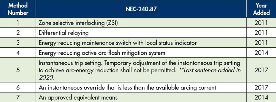
NFPA 70 (NEC) Article 240.87-2020 lists seven methods to reduce arc flash energy, whether in initial design and construction or on a retrofit project, including:
METHODS: THE GOOD, THE BAD, AND THE ALTERNATIVES
Each of the seven methods comes with pros and cons.
Zone Selective Interlocking (ZSI)
ZSI establishes a higher level of sophistication by reducing intentional short-time and ground-fault delays to shorten the fault-clearing time using communications between upstream and downstream breakers. In an existing selectively coordinated system, this communication scheme permits faults to be isolated and cleared by the nearest upstream device without an intentional time delay.
Pro: Allows selective coordination for faults outside of the zone and quick response to faults inside the zone (no intentional time delay).
Con: Requires hard wiring between each device, which can get complicated and tedious to install and test, making cost a factor.
Differential Relaying
This method requires the use of relays to detect and compare multiple currents to clear faults. The basic protection concept is that current flowing into the protective zone equals the current flowing out of the protection zone. Traditionally, differential relaying is used for medium-voltage applications. This method is typically designed and installed as a custom product.
Pro: Site and application-specific.
Con: Requires installation of relays and large current transformers (CTs) with increased space requirements, adding cost.
Energy-Reducing Maintenance Switch (ERMS) with Local Status Indicator
Manufacturers offer this option as an integral feature of circuit breakers that provide for installing a remote switch and indicator light. An ERMS switch is the second set of protection settings in a trip unit, typically with a lower instantaneous setting, designed to trip a breaker without any intentional delay during an arcing fault event. For example, let’s say protection settings A are used in normal operations and selectively coordinate with upstream and downstream equipment. Along with this coordinated system, there is a high AFIE. The maintenance switch is activated before performing maintenance on downstream equipment, switching to protection settings B, which alters settings to lower the AFIE. Once maintenance has been completed, the ERMS will be switched back to normal mode with protection settings A activated (along with the higher AFIE). This is a simple design with one possible drawback: In some instances, the maintenance switch does not get switched back, leaving protection settings B still activated. This allows settings overlap or mis-coordination between that device and downstream equipment, hence the reason for the local status indicator light. This oversight can have negative consequences depending on the load it is serving and could result in nuisance tripping.
Note if using this method: Manufacturers differ in philosophy regarding protection settings B. For example, some manufacturers’ protection settings B automatically set the instantaneous settings to low, while others allow B settings to be adjusted, offering more flexibility for the studies engineer. Your studies engineer must understand these differing philosophies and owner requirements.
Pro: A mid-ranged priced solution. The indicator light for ERMS activation makes this option relatively easy to use.
Con: Human error. The switch can be left in the maintenance mode position allowing for mis-coordination and nuisance tripping. Some manufacturers do not have flexibility in programming.
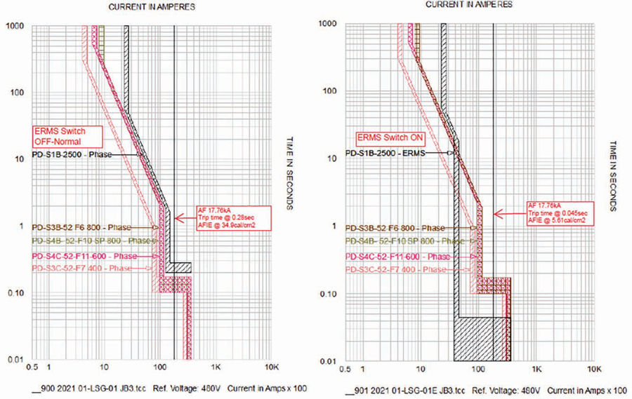
Figure 1: In this specialized field, studies engineers rely on coordination software to develop protection settings.
Energy-Reducing Active Arc-Flash Mitigation System
This is one of several special systems that automatically limit the energy released during an arc-fault event by one or more detection means. The following lesser-known concepts are based on NFPA 70E Annex O:
- One concept reduces the arc duration by creating a low-impedance current path for the arcing fault, allowing the upstream breaker time to clear the fault. Essentially, this method forces a bolted fault on the circuit, which transfers electrical energy to a new path, causing the upstream breaker to operate with no intentional delay.
- Another concept is to use an arc-flash relay with two components: light sensors to detect the light produced by the arc flash event and a current sensor (typically a CT) to detect the sudden rise in current. These two components, when detected simultaneously, send a trip signal to the protective device to operate without intentional delay.
- Another possible solution is an energy-reducing line-side isolation barrier enclosing the line-side conductors. This option protects workers from both shock and arc-flash events on the line side of the overcurrent protection device.
- Arc-resistant equipment can also be used to divert arc energy away from personnel.
Pro: Design can be specific to the end-user or specific application.
Con: Can get pricey from concept to design, installation, and testing.
Instantaneous Trip Setting
When this method was originally added, the industry treated it like a temporary maintenance switch, meaning the instantaneous setting would be lowered to reduce the AFIE to an acceptable level during maintenance work. However, problems arose as workers made random adjustments to the protective settings without a studies engineer calculating the actual arcing fault and advising which settings adjustments to make. This resulted in settings that did not lower the AFIE and falsely left workers thinking they were protected. Also, since there was no indicator light (as in method 3), settings were not adjusted back, or a random setting was reapplied because the worker didn’t remember the original settings. These human errors left the electrical system uncoordinated and could make the existing arc-flash label inaccurate, leading to additional unsafe work conditions. As a safeguard, a clarification added in 2020 states:
Temporary adjustment of the instantaneous trip setting to achieve arc energy reduction shall not be permitted.
The actual intent of this method is to have a studies engineer calculate the arcing-fault current and permanently set the protective settings to trip below this arcing current. The obvious problem with this method is that the settings might be adjusted so low that the coordination downstream can cause possible nuisance tripping.
Pro: Inexpensive solution, can be achieved with existing protection settings.
Con: Possible downstream coordination issues and nuisance tripping.
Instantaneous Override
An instantaneous override is a fixed, built-in factory trip setting protecting against fault currents above a breaker’s withstand capability. This setting is usually set higher than the standard instantaneous setting, and it usually protects against faults, but not always. This method should be used only when designing and installing new breakers and where the owner can have a voice in the design process. If the override function trips the breaker, coordination issues and nuisance tripping might occur.
Pro: Inexpensive option as there are no additional costs for new equipment.
Con: Possible coordination issues; might not be an option on existing equipment.
Approved Equivalent Means
This method was included to allow for any future technology. As technology continues to evolve, any equivalent method to the six listed above can be evaluated and approved by the Authority Having Jurisdiction (AHJ). This approval is usually obtained through prior discussion between the studies engineer and the AHJ.
BEST METHOD? DE-ENERGIZE!
The methods discussed above are provided if, and only if, there is a greater danger in not de-energizing. Article 110.4(A) summarizes the intent of NFPA 70E, Standard for Electrical Safety in the Workplace:
Energized work shall be permitted where the employer can demonstrate that de-energizing introduces additional hazards or increased risk.
CONCLUSION
What could be more dangerous than an electrocution or arc-flash incident that burns or kills a worker? If there is an arc-flash event in a facility and a worker is injured, the burden is on the owner to justify why they did not de-energize, and the consequences can include hefty fines and expensive lawsuits. Therefore, the priority must shift to de-energization. Owners and site operators need to find ways to de-energize and perform work safely. Just like PPE, these mitigation methods should be the last line of defense, not the first.
 David Rewitzer, PE, CEM, is a Power Systems Studies Engineer at Hood Patterson & Dewar. He specializes in electrical safety for MV and LV facility power distribution systems in data centers, large campuses, healthcare institutions, and commercial/industrial facilities. Dave has 30 years of experience in the electrical power industry. A licensed Professional Engineer in 13 states, he also teaches courses in arc-flash hazard awareness, electrical safety, power quality, and energy management. He is an OSHA-Authorized General Industry Trainer and currently participates in the IEEE 1584–2018, Guide for Performing Arc-Flash Hazard Calculations and IEEE 1584.1, Guide for the Specification of Scope and Deliverable Requirements for an Arc-Flash Calculation Study in Accordance with IEEE Std 1584TM working groups.