
Many types of equipment in the electrical transmission and distribution network perform a specific and necessary operation, and the circuit breaker is no exception, as it serves to protect the substation’s valuable assets. The circuit breaker — defined as a mechanical switching device — is unique: At one time, it must function as a nearly perfect conductor; at another time, it must function as a nearly perfect insulator, transitioning from one state to the other in a matter of milliseconds and occasionally dispersing enormous amounts of energy during the transition. To determine whether the mechanical switching function is working correctly, a time and travel analyzer is used to evaluate the operating characteristics of the circuit breaker.
When bulk oil circuit breakers were the prevalent technology in substations, travel measurements were performed without question. Over the years, due to lack of maintenance personnel and time for planned outages, as well as the complexity of hooking up a transducer to the circuit breaker, travel measurements have been performed less frequently. Time and travel measurements have been replaced with contact timing or reduced to first-trip testing. A 2012 study by CIGRE Working Group A3.06 found that 50 percent of major failures in a circuit were due to the operating mechanism; 30 percent were due to electrical control and auxiliary circuits. While contact timing and first trip are important tests and should be performed, they will not fully test the operating characteristics of the mechanism; travel measurements should be standard practice to determine the true health of the circuit breaker.
Basic Measurements with a Transducer
Although the transducer can be attached to the circuit breaker to determine the travel of different parts of its components such as the dashpot, the primary application of a motion transducer is to measure the motion of the main/arcing contacts in the circuit breaker. The transducer can be hooked to various parts of the circuit breaker: directly to the pull rod of the main contacts, directly to the mechanism, somewhere on the linkage, or even to an auxiliary switch.
Although the transducer provides many parameters, the most important measurement is the stroke of the circuit breaker. In fact, all other parameters are derived from the stroke of the circuit breaker, which is defined as the total travel distance of the contacts from resting position in one state (e.g., closed) to the resting position in the other state (open), or vice versa. It is imperative to be diligent in connecting the transducer to the manufacturer’s recommended attachment point on the circuit breaker and in correcting for any multiplication factors if a direct connection to the contacts cannot be made. At the very least, the technician must be consistent in measuring the stroke through periodic maintenance to trend the results. If the circuit breaker is gang operated, i.e., one mechanism operates all three phases, only one transducer is needed. If the circuit breaker has separate operating mechanisms for each phase, an individual transducer should be used for each mechanism.
Once the stroke of the circuit breaker is determined, the velocity of the contacts in different regions of the travel can be derived. The most common place to measure velocity is during the arcing zone of the circuit breaker, where it is actually interrupting or clearing the fault. Occasionally, damping is measured on the travel curve by calculating the velocity in the damping zone or the time between two predefined points on the travel curve in the damping zone.
By observing the closing time along with the travel measurement, the penetration or contact wipe can be determined. Penetration is the length measured from initial contact touch to the final resting position after the operation; contact wipe measures how far the contacts are engaged. Overtravel, which is measured directly from the travel curve, is the maximum displacement past the resting position that the contacts reach during the operation. After overtravel is measured, rebound is measured from minimum displacement to the final resting position of the contacts. Other parameters can also be determined, but they are all derivatives of the actual stroke measurement of the contacts, so it is important to connect the transducer correctly and to accurately measure the stroke of the circuit breaker. Figure 1 shows the various parameters that can be measured with a travel transducer.
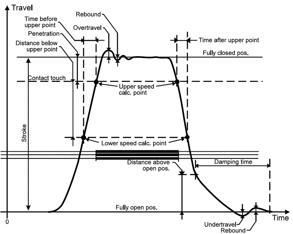
Figure 1: Typical Motion Trace
Transducer Types and Parameters Needed for Proper Measurements
Two types of transducers can be used to measure circuit breaker contacts: linear and rotary. A linear transducer measures a value of length typically in either inches or millimeters; a rotary transducer measures angle, typically in degrees, which must be converted to inches or millimeters. Various transducer designs — resistive, optical, magnetic, etc. — generally provide analog or digital output. The type of transducer to be used, rotary or linear, must be selected when setting up for motion measurements. Although either type of transducer works on many breakers, the manufacturer generally specifies a preference, and the manufacturer’s specified attachment point, transducer type, and conversion factor (if needed) should always be used.
Caution: Before connecting the transducer, always ensure the circuit breaker is in the open position and that no energy is stored in the mechanism. If it is impractical to discharge all the energy, as in the case of some pneumatic or hydraulic mechanisms, ensure the maintenance pin that blocks operation is set. Finally, de-energize the power going to the control circuitry. No matter where the transducer is placed, no part of the transducer, mounting bracket, or travel rod (if used) can be in the direct path of any moving parts of the circuit breaker. That will cause damage to the transducer or its accessories.
Linear Transducer
If a linear transducer is used, it must be of suitable length to cover the total travel distance the transducer will encounter, including overtravel, on both close and open operations. Linear transducers are available in a wide variety of lengths ranging from 25 mm or less, commonly used for vacuum circuit breakers, all the way up to 1,000 mm or more. Typical lengths are from 225–300 mm for SF6 dead tank circuit breakers and 500–600 mm for bulk oil circuit breakers. If the transducer is of questionable length, it is common practice to attach the transducer in one positon (e.g., closed), and then detach the transducer and operate the circuit breaker so it changes state. Now that the circuit breaker is in the opposite position (open), re-attach the circuit breaker to see if it is of suitable length. Once a transducer of adequate length is selected, determine whether the transducer will fit in the space provided.
Two types of measurements can be made with a linear transducer.
- In direct measurement (Figure 2), the transducer or linkage rod is connected directly to the moving contacts. Direct measurements are common in bulk oil circuit breakers, minimum oil breakers, most vacuum CBs, and some dead tank SF6 circuit breakers.
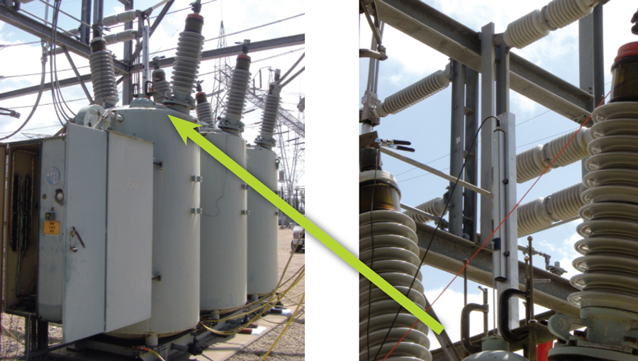
Figure 2: ITE Bulk Oil CB with Direct Linear Connection
Although finding a suitable mounting bracket and correctly mounting the transducer can be difficult, this method is beneficial because the actual stroke of the transducer is equal to the actual stroke of the contacts. Therefore, no conversion factor is needed, and all parameters measured with the transducer are direct representatives of the motion of the contacts in the circuit breaker. The motion isn’t distorted by gears, linkages, or any mechanical play of the interconnections. - In indirect measurement using a linear transducer (Figure 3), the transducer is connected not directly to the moving contacts, but to another part of the circuit breaker that is connected to the moving contacts, such as the mechanism or interconnecting linkage. When this type of connection is used, the travel of the transducer may or may not be equal to the travel of the main contacts. If the travel of the transducer is different, a conversion factor or ratio should be used to obtain the correct stroke length and travel parameters of the circuit breaker. For example, 80 mm of transducer stroke can be equivalent to 120 mm of contact stroke, so a multiplication factor of 1.5 should be used.
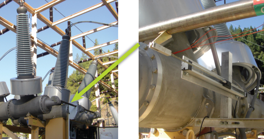
Figure 3: SF6 Dead Tank CB with Indirect Linear Connection
Rotary Transducer
When a rotary transducer is used, the measured quantity is in degrees, or occasionally radians, and is then converted to a unit of length using one of two types of conversions:
- In a constant conversion, one degree is equal to a certain value of length throughout the entire travel of the contacts. This is common where the mechanical linkage is simple with few interconnecting parts.
- When the linkage is more complicated, the ratio of the angle to length may not be constant throughout the total travel of the contacts; for example, 1 degree might equal 1.5 millimeters for the first 10 degrees; then for the next 10 degrees of travel, 1 degree might equal 2.5 millimeters. In these cases, a conversion table must be used to account for the varying values.
Rotary transducers have the advantage of being relatively small, and one kit with a few accessories can hook up to many different styles or types of circuit breakers. The disadvantage of the rotary transducer is that you must know the conversion factor or table to calculate the correct parameters of the circuit breaker. If the conversion factor or table is not provided in the manual, the breaker manufacturer should be contacted. Rotary transducers are most common on live tank SF6 circuit breakers, but are also used on certain types of dead tank SF6 breakers, bulk oil circuit breakers, and generator circuit breakers. Figure 4 and Figure 5 show examples of rotary transducer connections.
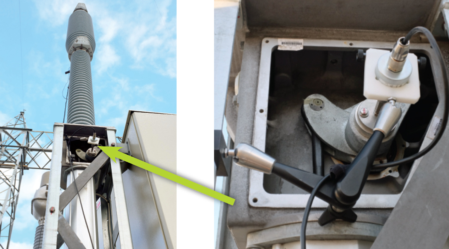
Figure 4: Rotary Transducer on SF6 Live Tank CB
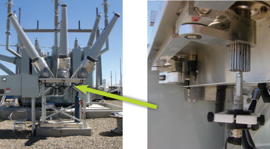
Figure 5: Rotary Transducer on SF6 Dead Tank CB
Velocity
Once the proper transducer and conversion factor are selected, most parameters, including stroke, overtravel, rebound, penetration, etc., will come out of the measurements automatically. One exception is the velocity measurement. To calculate velocity, the analyzer must be told where on the curve velocity should be measured. Two points on the travel curve are selected, and the average velocity between these two points is calculated. These points can reference various points on the curve such as distance below close, distance above open, percentage of stroke, distance below upper point, etc. Another common reference point is an event during the timing such as contact touch or contact separation. The two most important factors that influence the selection of the speed calculation points are (a) that the velocity is measured on a linear portion of the travel curve and (b) that it is measured during the arcing zone. Therefore, the calculation points are generally near contact touch on the close and contact separation on the open.
A common misconception when calculating velocity is to take the total travel distance (stroke) and divide it by the total time it takes for the contacts to reach the fully closed positon. This will not determine the velocity during the arcing zone; it will provide the average velocity for the total travel. In this case, the acceleration at the beginning of travel and the deceleration at the end will mask the instantaneous velocity around the arcing zone.
The speed calculation points can vary by manufacturer, type of circuit breaker, type of mechanism, etc., so the manufacturer should be consulted to select the proper speed calculation points. This information is generally available in the manual or in the original test report provided with the circuit breaker. If no information is given, it is recommended to use contact touch and 10 ms before for the close calculation points and contact separation and 10 ms after for the open calculation points. Table 1 provides a list of common transducer types and speed calculation points used by different manufacturers. The manufacturer or manual should always be consulted for proper transducer and speed calculation points.
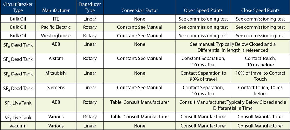
Table 1: Typical Transducer Types and Speed Calculation Points
Case Study: Siemens SPS2-38-40-2 Circuit Breaker
To investigate how transducer placement affects travel measurements, several transducers — rotary and linear — were attached to a Siemens SPS2-38-40-2 SF6 dead tank circuit breaker fitted with an FA2.20 mechanism. The breaker is rated at 38kV, is capable of interrupting 40k, has one break per phase, and is gang-operated (Figure 6).
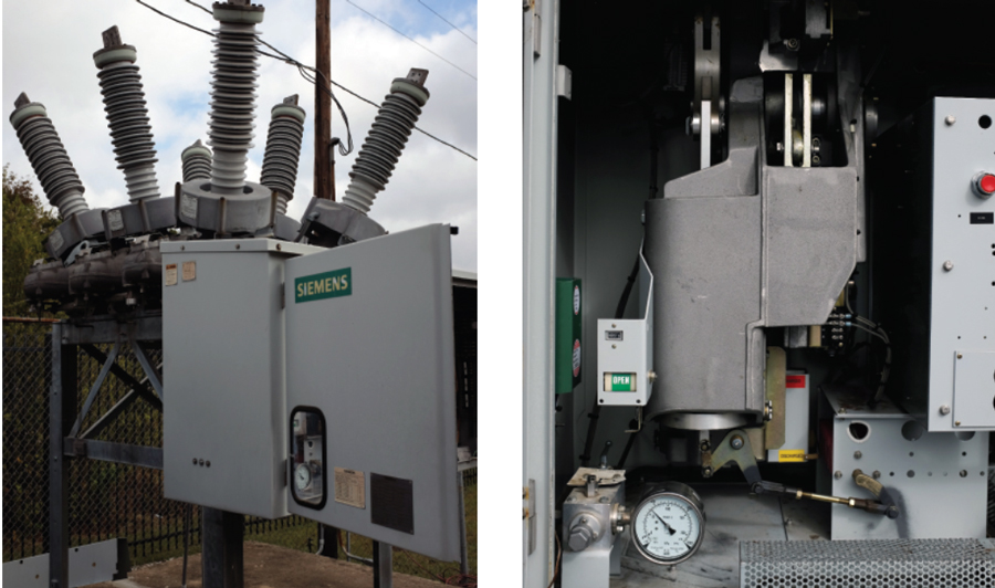
Figure 6: Siemens SPS2-38-40-2 CB with FA2.20 Mechanism
Siemens recommends measuring motion with a linear transducer attached to an actuating arm on the mechanism (Figure 7). They state that 80 mm of travel at the mechanism is equal to 120 mm of travel at the contacts, i.e., there is a 1.5 multiplication factor used to determine the true contact motion. They also state that the speed calculation points of contact touch and 10 ms before for the close operation and contact separation and 10 ms after for the open operation must be used.
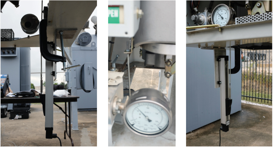
Figure 7: Transducer Connection Linear Mechanism
In addition to the standard transducer connection, four more transducer connections were made (Figure 8):
- One linear transducer was connected to the end linkage arm on the third phase.
- Three rotary transducers were attached to the rotating splines that drive the interrupter.
Figure 8: Transducer Connections (left to right) Linear Linkage, Rotary C, Rotary B, Rotary A
The same speed calculation points were used for all connections.
To compare the different transducer measurements, no conversion factors were initially used on the two linear transducer connections; a factor of 1 degree equals 1 millimeter was used for the rotary transducer. Figure 9 shows the motion traces from the three connections for a close operation; all three are scaled at 10 mm per division.
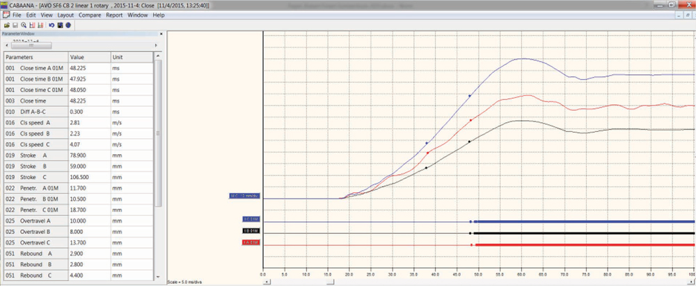
Figure 9: Close Operation, No Conversion: Linear Mech in Red (center), Rotary B in Black (bottom), Linear Linkage in Blue (top)
- M A (red), the linear transducer connected directly to the mechanism per Siemens recommendations, is referred to as Linear Mech.
- M B (black), the rotary transducer connected to the rotating spline on B phase is called Rotary B.
- M C (blue), the linear transducer connected to the end of the interconnect linkage near the rotating spline on C phase is referred to as Linear Linkage.
For all graphs, the bottom of the curve is the fully open position, and the top of the curve is the fully closed position. The timing for each phase where a thin line is open and a thick line is closed is also included. From the timing results, all three phases are relatively in sync with 0.3 ms difference between the slowest and the fastest phase with a close time of about 48 ms. As expected, the travel measurements vary widely across the connection points. The stroke for Linear Mech is 78.9 mm, Rotary B is 59.0 mm (degrees), and Linear Linkage is 106.5 mm. From these stroke measurements, the travel dependent parameters, i.e., velocity, overtravel, penetration, rebound, etc., will all vary by transducer placement.
An examination of the open operation shows similar variance in stroke values for the different connections (Figure 10).
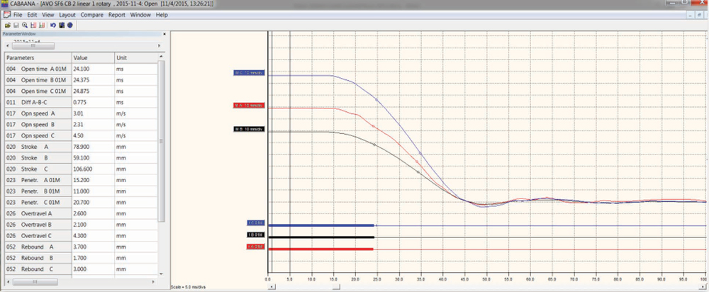
Figure 10: Open Operation, No Conversion: Linear Mech in Red (center), Rotary B in Black (bottom), and Linear Linkage in Blue (top)
The circuit breaker manual states that 80 mm of motion at the mechanism is equivalent to 120 mm of contact movement; therefore, with a transducer stroke of 78.9 mm, the contact stroke is determined to be 118.35 mm.
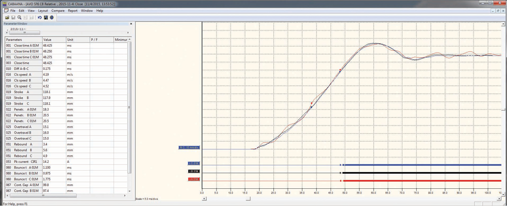
Figure 11: Close Operation, Conversion Factors Applied: Linear Mech (red), Rotary B (black), Linear Linkage (blue)
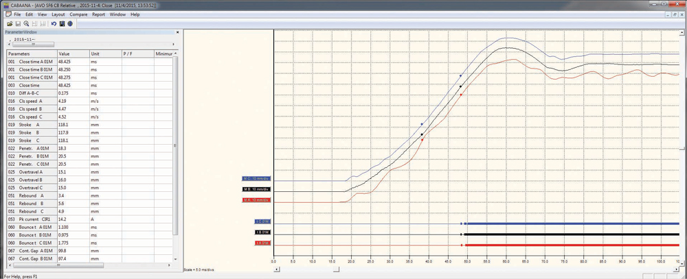
Figure 12: Close Operation, Conversion Factors Applied, Horizontal Axes Shifted to Show Detail: Linear Mech (red), Rotary B (black), Linear Linkage (blue)
Since the other transducers measured motion on the same operation, the ratios of the alternate linear transducer and rotary transducer can be calculated. Using simple algebra, the ratios of 59.0 degrees = 118.35 mm (Rotary B); 106.5 mm = 118.35 mm (Linear Linkage) are used to determine the conversion factors of 2.003 mm/degrees and 1.1099 mm/mm, respectively. With this information, the circuit breaker was measured again with the appropriate conversion factor applied to each transducer. The results are shown in Figure 11 and Figure 12 (close), as well as in Figure 13 and Figure 14 (open).
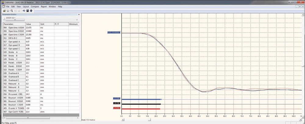
Figure 13: Open Operation, Conversion Factors Applied: Linear Mech (red), Rotary B (black), Linear Linkage (blue)
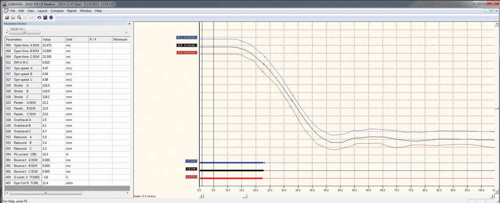
Figure 14: Open Operation, Conversion Factors Applied, Horizontal Axes Shifted to Show Detail: Linear Mech (red), Rotary B (black), Linear Linkage (blue)
These results show that, even with three different transducer attachment points and two different types of transducers, very similar results are produced as long as the correct conversion factor is applied. The maximum difference between stroke values is 0.2 mm on the close operation and 0.5 mm upon opening. Penetration, overtravel, and rebound are also very close for the three measurements. One interesting observation is that the travel trace of Linear Mech, the linear transducer connected directly to the mechanism, shows oscillation throughout the entire movement, and Linear Linkage, the linear transducer connected to the end of the linkage, shows slight oscillatory movement at the beginning and the end of travel. Flex in the travel rod and the connection of the rod to the transducer is most likely causing some of this movement. Additionally since Linear Mech is connected directly to the mechanism, the mechanism’s vibrations affect the motion throughout the entire travel. Since the close operation — closing the breaker and charging the opening spring — requires more energy, the effect is more apparent on the close operation.
Note that the velocity is different for each connection; this is partially due to the calculation points being based on contact touch and separation, so the variance in the timing affects where on the curve the velocity is calculated. On Linear Mech, the vibrations also affect the velocity calculations. If one of the speed calculation points rests on the crest of an oscillation and the other speed calculation point rests on the trough of an oscillation, the speed can vary dramatically compared to points taken on a neutral part of the oscillation. This effect can be seen by examining several operations in a row and observing that the velocity of Linear Mech can vary by 0.16 m/s or 3 percent, whereas the other two connections vary by a magnitude less. Play in the linkages will have some effect on the velocity calculations.
One last consideration is that a linear conversion factor was assumed, i.e., a conversion constant was used. Comparing Rotary B to Linear Linkage shows that they align better at the beginning and at the end of travel; in the middle of the movement, they diverge slightly, since this is the portion of the curve where velocity is calculated. It follows that the speeds would diverge slightly as well. If the geometries were analyzed and a conversion table was built for both connections, they would most likely overlap throughout most of the travel, and the velocities would align more closely.
The motion traces of the three rotary transducers can be examined to see how the same connection can be placed at different distances from the mechanism — at different parts along the interconnecting linkages — and yield similar results.
- M A on the graph (red), the rotary transducer connected directly to the rotating spline that drives the interrupter in A phase, is referred to as A phase.
- M B (black), the rotary transducer connected to phase B, is referred to as B phase.
- M C (blue), the rotary transducer connected to phase C, is referred to as C phase.
Figure 15 and Figure 16 show the results from a close operation.
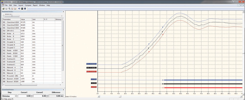
Figure 15: Close Operation with Conversion Factors Applied (bottom to top): Rotary A (red), Rotary B (black), Rotary C (blue)
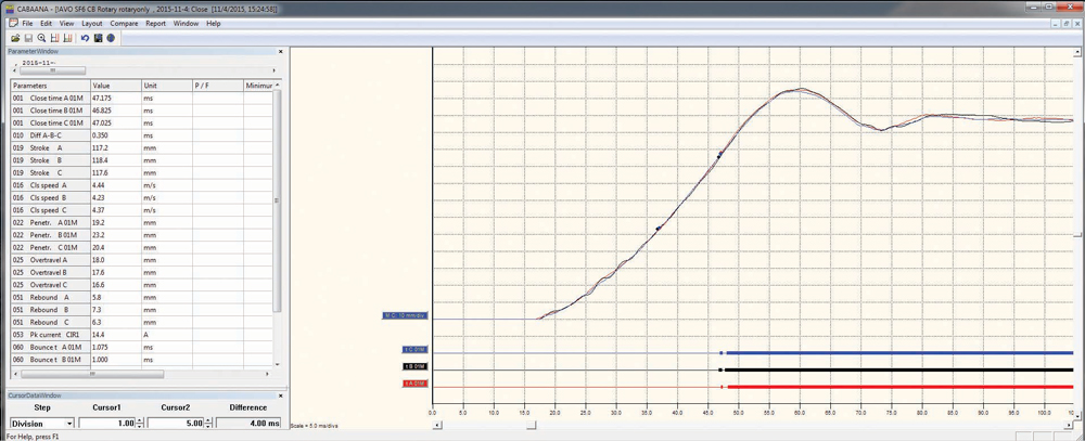
Figure 16: Close Operation, Conversion Factors Applied, Horizontal Axes Shifted to Show Detail: Rotary A (red), Rotary B (black), Rotary C (blue)
All three traces are similar with a variance in stroke of only 1.2 mm between the shortest and the longest phase. Note that phase A begins to move approximately 0.5 ms before phases B and C, which can be expected since it is the closest connection to the mechanism. Both A and C phases produce very smooth traces throughout the motion, but B phase shows some oscillations in the first 20 ms of travel. These oscillations are most likely due to a mechanical delay, as B phase is pushed by the linkage from A phase and then has to push the linkage to phase C. Any mechanical play within the connections between B and the other two phases results in small perturbations. The velocities of A and C are fairly close, but B phase is 0.2 m/s slower. This is most likely caused by two factors: First, the oscillations in the trace can cause different speed points to be taken; second, the timing of the three phases is slightly different and the speed calculation point is based on contact touch. Careful observation of the speed calculation points reveals that they do not line up in time.
The open operation in Figure 17 and Figure 18 shows even more consistency between the different phases.
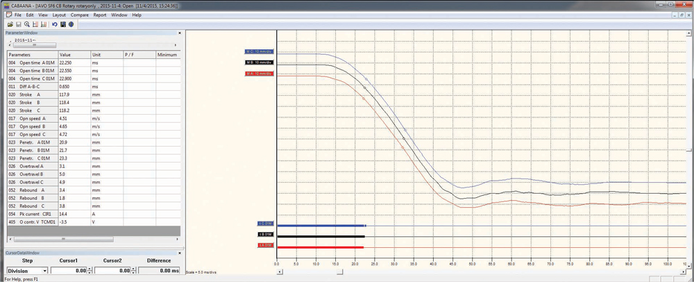
Figure 17: Open Operation, Conversion Factors Applied (bottom to top): Rotary A (red), Rotary B (black), Rotary C (blue)
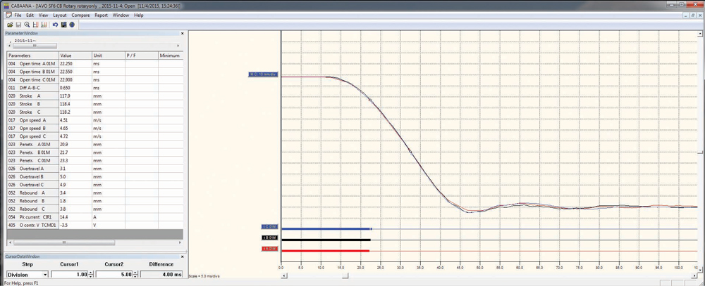
Figure 18: Open Operation, Conversion Factors Applied, Horizontal Axes Shifted to Show Detail: Rotary A (red), Rotary B (black), Rotary C (blue)
All three traces lay almost on top of each other with no deviation until the contacts reach the closed position. The stroke of the different phases is closer, with only a 0.5 mm difference between the shortest and the longest phase. The velocities of the three phases are different, but observing the contact times and speed calculation points shows that the velocity is calculated at slightly different points on each curve, thus changing the values slightly. If the speed calculation points are changed to reference below closed and a differential, then B and C phases travel at the same velocity, while A phase travels slightly slower because it has to push the other two phases.
What to Do if Very Little or No Information Is Provided by the Manufacturer
Occasionally, the manufacturer may not provide appropriate information for travel measurements, and it is left to the technician to decide which type of transducer to use and where to connect, what conversion factor/table to use (if any), and the proper speed calculation points for determining the velocity of the contacts. Careful consideration should be given before attaching a transducer and, once a method is determined, the same attachment and measurement parameters should be used in the future for trending purposes. Although these travel recordings provide valuable data and can be used for future reference, it should be noted that the values obtained may not necessarily be comparable to the factory test reports or parameter limits. No matter where the transducer is placed, no part of the transducer, mounting bracket, or travel rod (if used) must be in the direct path of any moving parts of the circuit breaker to avoid damage to the transducer and its accessories.
To decide where to connect the transducer, first determine whether connection directly to the contacts or actuating arm of the contacts is possible. If so, a linear transducer can be connected and the correct stroke, velocities, and other parameters will be measured without the need for a conversion table. If direct connection to the contacts is not possible, which is often the case, select a spot very close to the contacts with the minimal number of linkages between the connection point and the contacts. Either a linear or a rotary transducer can be used. Per IEC 62271-100, the mechanical characteristics can be recorded with a travel transducer at “convenient locations on the drive to the contact system where there is a direct connection, and a representative image of the contact stroke can be achieved.” Connecting directly to the mechanism can cause unwanted vibrations and influence the results; this should be avoided if possible. If an indirect connection is used, there are two options: Create a conversion table/factor or measure the absolute value of the motion, in either length or angle, and trend the results with the transducer connected in the same spot during future testing. If a conversion factor or table is used, the connection points and linkages can be examined and measured to develop a trigonometric function that relates the transducer movement to the contact motion. The function can also be determined from the circuit breaker’s mechanical drawings.
If the strokes of the contacts are known, another less accurate method of creating a conversion factor is to assume a linear relationship between the connection point and the contacts. The known stroke of the contacts can be divided by the measured stroke of the transducer to create the conversion factor. This value can then be used to measure the travel characteristics for initial fingerprint measurements and future testing. Note that if the relationship between the connection point and the contacts is not linear, the other stroke-dependent parameters such as velocity, overtravel, rebound, etc., may not be correct. Additionally, if this measurement is made when there are issues with the circuit breaker, i.e., the stroke is not correct, the subsequent measurements will also be incorrect. If other circuit breakers of the same type are available, it is beneficial to compare measurements to verify the correction factor.
If no speed calculation points are provided by the manufacturer, use contact touch and 10 ms before for close and contact separation and 10 ms after for the open. This assures that the velocity is measured in the critical arcing zone of the interrupter. Remember that once a method of transducer connection, conversion factor, and speed calculation points is used, the same method should continuously be employed through the life of the circuit breaker to trend the results.
Conclusion
Circuit breakers are a key element in the electrical transmission and distribution network throughout the world. IEEE Std. C37.09 states: “Travel-time curves shall be obtained for all outdoor circuit breakers with an interrupting time of three cycles or less,” and NETA requires time and travel analysis on medium- and high-voltage SF6 and oil circuit breakers. To verify that the circuit breaker will operate effectively when called upon to protect various assets in the network, time and travel analysis must be performed.
References
IEEE Std. C37.100-1992 (R 2001), IEEE Standard Definitions for Power Switchgear.
CIGRE TB 510, “Reliability of High Voltage Equipment – Part 2: SF6 Circuit Breakers.” Working Group A3.06, 2012.
Siemens, Type SPS2-38-40-2 “Circuit Breaker Manual.”
IEC 62271-100, International Standard High-voltage Switchgear and Controlgear – Part 100: Alternating-current circuit-breakers.
CB Testing Guide AG en V02, “Megger Circuit Breaker Testing Guide,” 2012.
IEEE Std. C37.09-1999 (R2007), IEEE Standard Test Procedure for AC High-Voltage Circuit Breakers Rated on a Symmetrical Current Basis.
ANSINETA ATS, Standard for Acceptance Testing Specifications for Electrical Power Equipment and Systems – 2013 Edition.
 Robert Foster, an Applications Engineer with Megger, specializes in high-voltage circuit breaker and transformer testing. In his current role with Megger, he is involved with customers and product development, supporting products and applications throughout North America. He previously was a Field Service Engineer for ABB in the high-voltage dead-tank circuit breaker division. Robert graduated from California State University, Chico, with a BS in physics and mechatronic engineering.