
While the basic premise of transformer differential protection is straightforward, numerous features are employed in modern relay algorithms to compensate for challenges presented by the transformer differential application. As a result, developing appropriate test quantities and properly quantifying results can be challenging with traditional functional differential testing.
Challenges in Traditional Functional Testing
A traditional functional test assures that all measurements and derived quantities are measured and calculated accurately, and that the overall relay hardware — including inputs and outputs — function properly. Therefore, the test quantities of a traditional functional test are defined as a sequence of steady-state or phasor values. This type of testing is frequently performed throughout the life cycle of a relay. During commissioning, this type of test can further assure whether threshold and time elements are set according to the settings specified by engineering. The following sections describe typical tests and their challenges.
Pickup Testing
Even the simple differential element pickup test, when performed manually, requires the test designer to calculate the nominal operating current amplitude, or tap, for each winding. The currents on the winding are simply increased from zero until the relay trips. The pickup current value is then converted back to per-unit and compared to the setpoint.
Slope Testing
For differential characteristic tests in the slope region, the proper phase shift is determined from the transformer three-line diagram. For three-phase tests, balanced quantities of a given multiple of tap and phase shift matching the application are applied to two or more current windings, which simulates a balanced load. Currents on one side are then incrementally increased until the differential element operates. For tests of a single differential element phase, realistic through-fault current phasors must be calculated. Evaluating the results of slope characteristic tests is not straightforward as there is significant variation in the restraint current calculation between differential relay manufacturers such as the maximum per-unit phase current, minimum per-unit phase current, average per-unit phase current, sum of the per-unit phase currents, or other calculations. In addition, some differential relays incorporate a reference winding in the restraint calculation that can be fixed or calculated automatically.
If the simulation of single-phase faults is desired, calculation of test values is more complex, and the relay’s method of zero-sequence elimination must be considered. To simplify this process, dedicated software tools exist that calculate the required steady state quantities by using an internal transformer model. The software module can then directly inject the quantities, measure back the pick-up or trip signals, and assess the steady state accuracy. These tools have limitations when the relay applies adaptive characteristics or works in the time domain instead of the frequency domain.
To further complicate testing, modern relays incorporate several additional characteristic features. For example, some relays incorporate cubic splines to smooth the transition between slope 1 and slope 2 (Figure 1). Testing in the cubic spline region requires additional calculations.

Figure 1: Transformer Differential Relay Incorporating a Cubic Spline in the Differential Operating Characteristic
Another feature that can complicate testing is an adaptive slope characteristic (Figure 2). These schemes are applied to restrain operation of the differential elements for external faults that might cause current transformer (CT) saturation, unbalancing the differential, and cause a mis-operation.
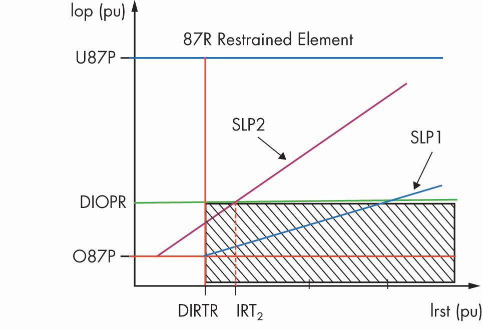
Figure 2: Adaptive Slope Characteristic and Supervisory Relay Word Bits Used by SEL-487E Transformer Differential Relay
When functional testing a differential characteristic incorporating an adaptive slope, the applied slope is determined by pre-fault current. To test slope 2 on these devices, pre-fault state duration and pre-fault current amplitude are coordinated with the relay settings, which causes the relay to shift to a high security mode. Of course, traditional ramping tests cannot be used in these cases. Instead, the characteristic is verified by applying a series of tests incorporating rest, pre-fault, and fault states.
Inrush and Overexcitation Blocking
To restrain the differential element during magnetizing inrush, most relays use both the 2nd and 4th harmonic content of the calculated phase differential currents (Figure 3).

Figure 3: COMTRADE Recording of Transformer Inrush Showing Time Domain Plot (left) and Calculated Harmonic Content at the Time Indicated by the Yellow Marker (right)
During inrush, 2nd harmonic content of the resultant current varies with closing angle. To prevent mis-operations of the differential element due to closing angle, modern digital relays incorporate a variety of special schemes. The most common uses the highest measured harmonic in any phase to restrain all phases. However, other devices use cross-phase averaging, where the average even harmonic content in all phases is used to restrain the differential in all phases, which can substantially complicate testing. In these cases, test operators frequently use only three-phase tests, leaving these features untested. To test these elements, composite waveforms containing fundamental frequency and the harmonic under test are used. One test method consists of increasing fundamental current until the relay operates, then increasing only the harmonic content until the relay restrains, then calculating the harmonic percentage and comparing to the relay settings.
A completely different inrush blocking algorithm analyses the current signals in the time domain. If the current dwells close to zero and is unipolar, it is considered an inrush condition. This method has better sensitivity on new core materials that generate very low 2nd harmonic content on inrush. This type of algorithm cannot be tested with traditional functional testing methods.
In addition to inrush conditions, transformer magnetizing current can also increase during transformer overexcitation, possibly resulting in an improper differential element trip. To mitigate this possibility, the 5th harmonic content of the differential current is measured, and if a preset threshold is reached, the differential element is either desensitized or completely restrained (Figure 4).

Figure 4: Differential Characteristic Illustrating Operation of the 5th Harmonic Restraint in a Beckwith Transformer Relay. When the 5th harmonic threshold of the differential current is reached, the differential element pickup setting is increased to prevent mis-operation. As with inrush, testing is performed using a composite waveform consisting of the fundamental and 5th harmonic frequencies.
Restricted Earth Fault
Restricted earth fault, or ground differential elements are gaining popularity. Related to the transformer differential element, restricted earth fault elements protect against faults occurring near the neutral end of wye-connected transformer windings. In these schemes, the calculated zero sequence current from the wye winding phase currents is compared to the measured ground current (Figure 5).
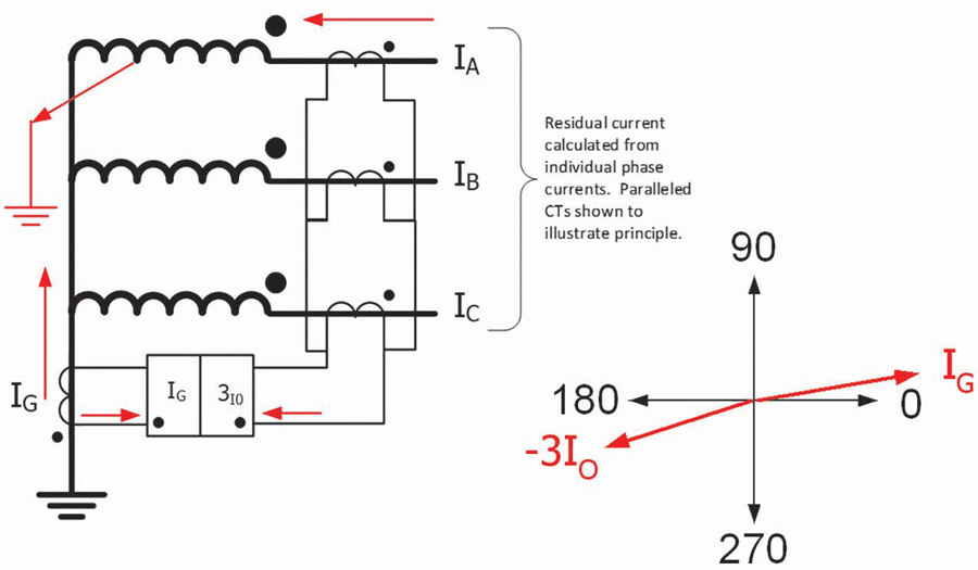
Figure 5: Restricted Earth Fault on Transformer Phase (left); Resultant Phasor Diagram (right)
Functional testing of these schemes requires the test designer to properly calculate phase-current phasors for internal and external faults to check proper operation. Additional logic is also incorporated to create operating windows and provide protection when the transformer is energized from one side only.
Is This Testing Adequate?
Even after surmounting the challenges of functional testing, the fundamental question of setting adequacy remains mostly unanswered. If the relay does not operate quickly, securely, and dependably during a power system event, the goal of the protection system has not been met. There may be a better way.
System-Based Testing of Transformer Differential Protection
A system-based testing approach can reduce testing challenges and ensure the settings are adequate. The idea is simple:
- To ensure the relay trips for an internal fault, simulate realistic internal faults to test the response of the relay.
- To ensure the relay is secure against tripping for through-faults, simulate realistic through-faults and verify the relay does not operate. Thus, a system-based testing solution calculates the testing quantities within a subtransient power system simulation, directly outputs the signals with an amplifier, measures the response, and assesses the result.
Transformer Simulation
When defining a system-based test case, do not think about the element or algorithm under test; instead, consider the power system incidents this element is supposed to act on, for example:
- Faults external to the protected zone
- Faults internal to the protected zone
- Turn-to-turn faults
- Turn-to-ground faults
- Inrush during energization
- Transformer overexcitation due to overvoltage
- CTs saturation and ratio errors
The electromagnetic transient (EMT) simulation of these incidents is one of the cornerstones for a system-based testing solution. The reliability of a simulation result depends on accurate input data. To make the testing tool practical for technicians and engineers in the field, we must find a solution that yields numerically stable and reliable results and apply heuristics where data is not available.
Transformer Model
Relevant power system scenarios include low-frequency transient events such as faults as well as low-frequency non-linear phenomena such as inrushes and overexcitation. High-frequency phenomena in the power system are not relevant to the transformer protection relay due to internal algorithms and the cut-off frequency of anti-aliasing hardware filters. Therefore low-frequency transformer models are suitable for system-based transformer protection testing.
The more physical, geometrically based, and detailed the transformer model is, the more accurate simulation results will be. However, parameter availability imposes the major constraint on the accuracy of the simulation results in the field. From a field technician perspective, the main source of information is the transformer nameplate. Information about core material and dimensions, number of winding turns, and geometry of the winding is not normally available. Thus, it is important that the model can be parametrized from nameplate data using reasonable heuristics that are based on guidelines provided in international standards and by expert working groups.
The mutually coupled coils model that is used in the described solution was proposed by Brandwajn and Dommel and offers a reasonable compromise between precision and parameter detail. The same principle is utilized in various free and commercial EMT simulation tools.
External Faults
The fault current contribution to an external phase fault mainly depends on the positive sequence impedance of the transformer, which can be derived from the short-circuit voltage on the nameplate. However, the simulation of ground faults requires reasonable zero-sequence short-circuit impedances for the transformer that are not always available on the nameplate. The zero-sequence impedance is influenced by the core type, vector group, presence of a compensation winding, and neutral grounding. Figure 6a – Figure 6f show how these factors affect the zero-sequence equivalent circuit of a two-winding transformer. P, S, M, N, and C in the figure subscripts denote primary, secondary, magnetizing, neutral, and compensation, respectively.
6a Positive-Sequence Equivalent Circuit
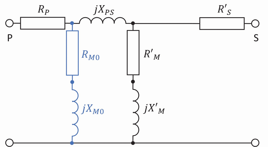
6b Influence of Three-Limb Core
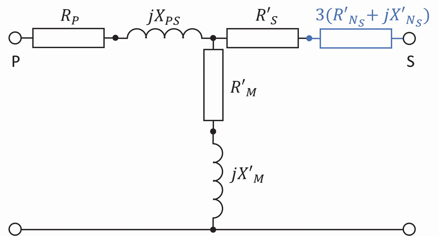
6c Influence of Grounding Impedance
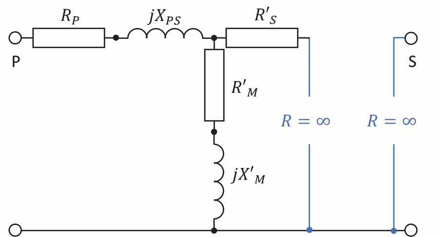
6d Influence of Wye-Winding with Isolated Neutral

6e Influence of Delta Winding

6f Influence of Compensation Winding
Figure 6: Influence of Various Factors on Two-Winding Transformer Zero-Sequence Equivalent Circuit
The effect of core type and compensation winding on transformer zero-sequence impedance can be estimated using heuristics, based on the guidelines in ISO/IEC 60076-8:1997. Accordingly, a system-based testing solution heuristically estimates unknown impedances:
![]()
based on a transformer positive-sequence, short-circuit impedance ![]() where:
where:
![]()
![]()
Internal Faults
For the simulation of internal transformer faults, the system-based testing solution relies on a widely accepted method described in Bastard et al. The method extends an original, mutually-coupled-coils transformer model, splitting the faulted coil into two sub-coils in the case of turn-to-ground faults and into three sub-coils in case of turn-to-turn faults, therefore allowing a branch with a fault resistance RF to be inserted in the newly introduced terminals between the sub-coils (Figure 7).

Figure 7: Splitting Faulted Coil of Wye Winding into Two Parts (left) and Faulted Coil of Delta Winding into Three Parts (right).
Determining the short-circuit impedance of the split sub-coils requires knowledge of the inductive leakage factors, which again are not specified by a transformer nameplate. To estimate inductive leakage factors, detailed transformer geometrical data would be required. Since the data is not commonly accessible for relay protection engineers, we are left to rely on heuristic estimations of inductive leakage factors.
Different heuristics were proposed in M. Kezunovic et al, Darwish et al, and Palmer-Buckle et al. Keeping our use case in mind, the most challenging scenario for the sensitivity of a restricted earth fault protection function is faults close to the neutral with just a few short-circuited turns and high fault resistance. In such a scenario, the principle of proportionality plays a higher role than the principle of leakage. In other words, a contribution of fault and winding resistance to the equivalent short-circuit impedance is higher than a contribution of leakage inductance. Therefore, different inductive leakage factor heuristics yield similar simulation results for many test scenarios.
Saturating Core
All differential relays must incorporate features to provide security during magnetizing inrush and transformer overexcitation, both sources of significant differential current during these events. To achieve realistic simulated waveforms for these phenomena, the non-linear saturation characteristic of the transformer core must be simulated. Therefore, an iterative approach for inclusion of non-linear inductors into the solution is utilized.
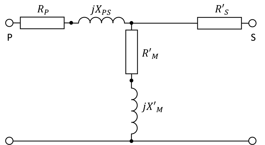
To simulate the non-linear transformer core, the system-based testing solution takes winding resistances and the magnetizing branch out of the mutually-coupled transformer coils model and transforms the magnetizing branches from series R-L circuits to parallel R-L circuits with non-linear inductor (Figure 8).

Figure 8: Switching from Series to Parallel R-L Circuit
For a core-type transformer with concentric windings, Cigre Working Group 33.02 recommends placing the non-linear inductor across a coil closest to the core. The saturation of yokes and unwound limbs (for a five-limb transformer) in the transformer model are neglected, as a reasonable estimation of their saturation characteristics requires detailed knowledge of transformer design parameters or results of non-standard transformer tests. The advantage of using only three non-linear inductances per transformer includes a better simulation performance and simpler parametrization compared to more sophisticated non-linear transformer models.
For scenarios with residual flux (or remanence), the testing solution uses a non-linear hysteretic inductor model based on the principles of EMTP Type-96, which is widely accepted in power system simulations.
Setting Up and Executing a System-Based Test
While all these details of the simulation are daunting, they are taken care of by the modelling in the software. Compared to functional testing, the test setup is much simpler. Starting from a standard power transformer topology (Figure 9), only the CT ratios and the transformer nameplate data must be entered:
- Vector group
- Rated voltages
- Rated power
- Short circuit voltage / impedance
- No-load current
- Core type

Figure 9: Single-Line Diagram and Transformer Parameterization for System-Based Testing
The parameters for the saturating core are set automatically to typical values according to heuristic estimation of magnetization characteristic parameters outlined in Cigre and Colombo and Santagostino and usually do not have to be adapted.
Test Cases
Defining a system-based test document requires some rethinking of existing testing procedures. For example, instead of defining a 2nd harmonic content, we simulate the energization of the power transformer at various closing angles. Instead of defining a differential and restraining current, we simulate through faults and internal differential zone faults. All these scenarios can be defined within a single-line diagram of the transformer and the surrounding power system.
From a systematic standpoint, a test document starts with a metering check, followed by test cases for stability. The differential relay is not supposed to trip for normal load current or faults on the buses outside of the differential zone. It may happen that the overcurrent element trips with some time delay for outside faults. The fault can be dragged from a toolbar in the software and dropped on the bus.
To test the differential trip, the fault can also be dropped on the power transformer. For a turn-to-ground fault close to the star-point (<5%) a differential element might not be sensitive enough; therefore, a REF element, if applied, will pick up the fault. Similarly, for turn-to-turn faults with both terminals close to each other, the differential element might not be sensitive enough; a negative sequence element might pick up this type of fault.
To test stability during inrush, both breakers are in an open state. Within the test case, an event will close the breaker, causing an inrush condition. By changing the closing angle, the amount of inrush in each phase can be altered.
Apart from these major test cases, additional real-world scenarios can be tested, including sympathetic inrush, fault during inrush, external faults with CT saturation, and overexcitation due to overvoltage (Figure 10).

a) Fault incident during energization
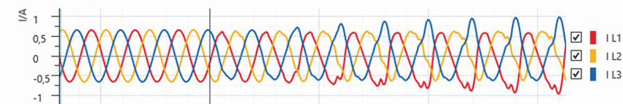
b) Sympathetic inrush due to energization of parallel transformer

c) CT Saturation during external fault
Figure 10: Time Domain Plot from a System-Based Testing Case Illustrating Inrush and Resultant CT Saturation
Since a system-based testing solution can control multiple test sets from one PC’s software, three-winding transformers or REF protection can be tested without rewiring the test setup. Protection schemes for phase shifting transformers can be tested the exact same way without adding complexity. Line protection systems where the transformer is within the protected zone can also be easily tested.
Benefits & Drawbacks
The biggest benefits of the system-based test approach are simplicity and the ability to ensure the protection system is working under real-world conditions. As it is relay independent, the test document for the same type of transformer is identical, independent of the relay manufacturer. And because it only simulates realistic incidents, it will work for every relay algorithm improvement in the future.
On the downside, system-based testing requires some rethinking of existing testing procedures. The harmonic content of the test signal during an inrush is realistic for the type of transformer, but it cannot be set exactly below or above a certain threshold. Therefore, functional testing still has its place.
Conclusion
So where do we invest our precious testing time and resources? If a differential relay is accurate when set to a certain threshold and has been tested several times throughout its lifecycle — for example during prequalification — functional testing is sufficient. But if the goal of commissioning is to ensure that a differential relay and its engineering adequately protect the power system and transformer, system-based testing is the right tool.
References
V. Brandwajn, H. W. Dommel, and I. I. Dommel. “Matrix Representation of Three-phase N-Winding Transformer for Steady-State and Transient Studies,” IEEE Transactions on Power Apparatus and Systems, Vols. PAS-101, No. 6, pp. 1369-1378, 1982.
ISO/IEC 60076-8:1997, Power Transformers — Application Guide.
P. Bastard, P. Bertrand, and M. Meunir. “A Transformer Model for Winding Fault Studies,” IEEE Transactions on Power Delivery, Vol. 9, No. 2, pp. 690-699, 1994.
M. Kezunovic, B. Kasztenny, and Z. Galijasevic. “A New ATP Add-On for Modeling Internal Faults in Power Transformers,” American Power Conference, Chicago, 2000.
H. A. Darwish, A. I. Taalab, and H. E. Labana. “Step-by-Step Simulation of Transformer Winding Faults for Electromagnetic Transient Programs,” 2005/2006 IEEE/PES Transmission and Distribution Conference and Exhibition, Dallas, TX, 2006.
P. Palmer-Buckle, K. Butler, N. Sarma, and A. Kopp. “Simulation of Incipient Transformer Faults,” 1998 Midwest Symposium on Circuits and Systems (Cat. No. 98CB36268), Notre Dame, IN, USA, 1998.
CIGRE Working Group 33.02 Internal Overvoltages. TB 039, Guidelines for Representation of Network Elements When Calculating Transients, https://e-cigre.org/publication/039-guidelines-for-representation-of-network-elements-when-calculating-transients.
E. Colombo and G. Santagostino. “Results of the Enquiries on Actural Network Conditions when Switching Magnetizing and Small Inductive Currents and on Transformer and Shunt Reactor Saturation Characteristics,” Electra, Vol. 94, pp. 35-53, 1984.
J. G. Frame, N. Mohan, and T. Liu. “Hysteresis Modeling in an Electromagnetic Transient Program,” IEEE Transactions on Power Apparatus and Systems, Vols. PAS-101, No. 9, pp. 3404-3412, 1982.
George Alexander, David Costello, Brad Heilman, and Jason Young. “Testing the SEL487E Relay Differential Elements,” SEL Application Guide, Vol IV AG2010-07, p 11.
 Scott Cooper is the Application and Training Engineer for OMICRON in St. Petersburg, Florida. He has thirty years of experience in a variety of roles including substation commissioning, application engineering, power plant operations, and technical training. He is active in the IEEE PSRC and has written numerous papers and magazine articles. Scott is a graduate of the United States Navy Nuclear Propulsion program.