

Circuit interrupters or breakers are used to isolate and prevent sustained faults. These breakers have various types of failure modes which include trip coil failure, trip circuit opening, mechanical latch malfunction, and insulating gas leaks, to name a few.
A sustained fault is recognized when it takes longer to isolate it than the sum of the normal relay and device operating times. Because time is of the essence when clearing faults on the power system to avoid destabilization and further damage, critical clearing time studies are performed to determine the maximum amount of time that faults can be sustained before cascading failures occur.
Breaker failure protection schemes are developed from critical clearing time studies and are implemented to minimize the elapsed time between a fault being detected and ultimately extinguished, allowing the system to regain stability. It is a high-speed protection scheme that trips surrounding interrupting devices in case the initial intended device should fail.
This article discusses various causes for breaker failure, what breaker failure protection is, as well as several types of breaker failure protection implementations, and how they can be tested.
BREAKER FAILURE
To define breaker failure protection, we should first answer: What is breaker failure?
Breaker failure can be defined as a misoperation or failure of a circuit breaker to operate as intended. This can result in failure to trip, close, and/or clear. When this occurs, fault current continues to flow through system devices, possibly above their rated ampacities, causing irreparable damage to conductors, circuit breakers, transformer windings, hardware, etc. Even when the main contacts of the circuit breaker fully open, conditions may exist in the dielectric medium that prevent the arc from being extinguished, thus allowing current to continue flowing towards the fault. These examples often lead to catastrophic failure of the current interrupting device which requires a protection scheme to quickly identify a breaker failure condition when it occurs and take measures to isolate the failed device.
The most common types of breaker failure modes are:
- Failure to trip is a breaker failure condition characterized by a circuit breaker failing to operate following a trip signal being generated.
- Failure to clear is declared when the contacts open but fault current continues to flow after a preset time following a trip signal being transmitted to the circuit breaker.
Although not typically considered a breaker failure condition, failure of a breaker to close when intended to can cause serious issues with fault location isolation and restoration (FLIR) and other automation systems. Slow closing can also be considered a type of breaker failure given the issues it may cause in generation during synchronization.
Why Do Breakers Fail?
Mechanical causes of a circuit breaker failing to open or otherwise clear a fault following a trip signal include worn, damaged, or obstructed components of the tripping mechanism. Vegetation, bird/animal nests, and ice are potential obstructions to consider. Every environment presents unique challenges and vulnerabilities. Thorough and timely inspections are only part of a comprehensive preventive maintenance plan. Care should always be taken to avoid placing tools in or around moving parts and account for them before placing the device into service.
Too many operations can overwear linkage components and affect the timing and travel of fault-interrupting components. Extended times without properly exercising the trip mechanism can lead to parts seizing or becoming obstructed through forces of nature. Best practice is to follow a maintenance procedure that meets or exceeds the manufacturer’s specifications. Anticipate how the environment may require more frequent attention.
Electrical causes for breaker failure incidents are less common than those due to mechanical problems. Broken or damaged control wiring, loose terminal connections, undervoltage conditions, and trip-coil failure are just a few possible reasons for a circuit breaker to fail to open following a trip signal. Increasing generation capacity, which increases the fault current levels, without increasing the size of the breaker can create fault currents that exceed the current interrupting capability of the breaker and may also prevent or delay the fault being cleared.
BREAKER FAILURE PROTECTION
IEEE Std. C37.119–2016, IEEE Guide for Breaker Failure Protection of Power Circuit Breakers defines breaker failure protection as:
…a form of protection that is designed to detect the failure of a circuit breaker to operate or to interrupt a fault. Upon detection of a breaker failure during a fault condition, the scheme is designed to take appropriate action to clear the fault. Upon detection of a breaker failure during a non-fault condition, the scheme may take other appropriate action.
Breaker failure protection is thus intended to provide high-speed detection and isolation of a failed breaker and, of course, the fault. This is accomplished by opening, locking out, and blocking the close of all available sources that could feed the circuit breaker. Without this, the fault may not clear until adjacent and upstream devices have recognized a trip condition and operated successfully. Even so, unless a lock-out condition has been identified, reclosing into the failed device and a fault are likely.
When Is Breaker Failure Protection Used?
Breaker failure protection can be used at any voltage level but is typically implemented on distribution-level systems and above. Whether a breaker failure condition could have a greater effect on system stability determines the need for this type of protection scheme.
Breaker failure protection is used not only as a high-speed backup for the asserted trip element intended to isolate the fault and protect downstream devices (remember, a specific trip condition was met before a signal was sent to the circuit breaker to open), but also to mitigate system instability caused by circuit overload, voltage sag, equipment damage, and cascading system failures. Prolonged faults on a system destabilize the local network and have the potential to propagate higher into the system and magnify the effects. Catastrophic damage to the failed breaker, which can significantly increase repair costs, can also be avoided with proper operation of the breaker failure protection scheme.
Operation Theory
Breaker failure protection logic is a backup protection scheme intended to guard against situations where the protection system calls for a breaker trip to isolate a fault and the breaker fails to trip and clear the fault as expected. This requires tripping further out from the fault while minimizing the additional impact to the power system. Like any protective scheme, there are several ways to implement this type of protection, each with advantages and disadvantages.
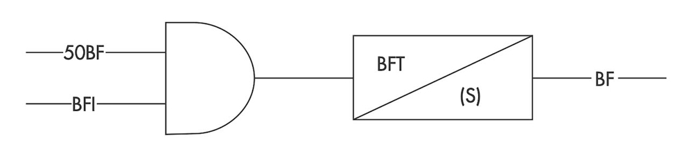
In its most basic implementation, a breaker failure protection scheme follows the logic shown in Figure 1. As shown, a protective relay trip signal (BFI) and the presence of current circulating in the breaker (50 BF) are both required for the breaker failure output to be activated after a certain amount of time.
Three primary attributes must be considered when designing and implementing a breaker failure protection scheme.
- Sensitivity: Can any overreaching elements in adjacent zones of protection reliably detect faults in the entirety of the zones to which they provide backup protection?
- Selectivity: Can we limit and accept the potential of the scheme to overtrip parts of the power system that may have otherwise stayed operational?
- Speed: Have we considered potential impacts to power quality and system stability as well as possible fault stress on equipment from delayed clearing times caused by the timing needed for the scheme?
The total time required for the fault to be cleared in the presence of breaker failure is the total sum of the primary protective relay time, the breaker failure initiate time, the breaker failure timer, the trip or lockout relay time, and the local or backup breaker interrupt time. This can be seen in Figure 2.

There is no one-size-fits-all solution for every power system, so responsible engineers must carefully consider the balance between possible under- or over-tripping. The best solution typically relies upon other protection schemes in the system to cover any potential shortfalls of the breaker protection scheme
BREAKER FAILURE BACKUP SCHEMES
Remote Breaker Failure Schemes
Remote BFP schemes utilize over-reaching elements in surrounding zones to sense the failure of a fault to be isolated as expected by the first-choice breaker tripping. These schemes were common in older systems using electromechanical and solid-state relaying. However, there are several drawbacks inherent in the way these schemes operate.
If multiple overreaching trips respond to the same fault, outages can spread. The time delays needed to help secure against the BFP trip occurring at the same time the expected breaker is responding can lead to prolonged disturbances in the system and the potential for stress on otherwise unfaulted equipment and increased system instability.
Finally, it can be challenging to design settings such that faults can be seen properly at the farthest remote ends of protected lines without them becoming overly sensitive to faults closer in, creating the possibility of misoperation during times of heavy load or more extreme transients.
An example of remote breaker failure protection can be found in Figure 3. For a fault between Breaker 3 and Breaker 4, both should trip and clear the fault. If Breaker 3 fails to clear the fault, then Breaker 1, Breaker 6, and Breaker 8 will trip clearing the fault. Since Breaker 1, Breaker 6, and Breaker 8 are not on the same substation as Breaker 3, this is considered a remote breaker failure protection scheme.
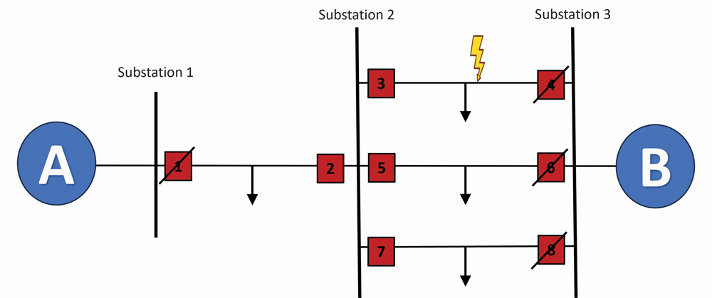
A drawback of this scheme is that by tripping the remote breakers, service is lost for all customers between Substation 1 and Substation 3 rather than only on the faulted line between Breaker 3 and Breaker 4. To overcome this limitation a local breaker failure scheme is developed, which will be shown in the next section.
Local Breaker Failure Schemes
Local BFP schemes instead rely upon communication between relaying at multiple breakers within the same substation or facility. This additional logic local to the breaker allows for faster clearing times due to the shorter timers made possible by the relays directly knowing when another has called for a trip and can also increase the specificity of the backup tripping scheme, limiting the potential for unnecessarily widespread outages. While these schemes were prohibitively expensive to implement in the past due to the need for additional equipment, the integration of the necessary logic into modern multi-function microprocessor relays has greatly decreased the cost and complexity of utilizing them. However, it is critical to consider the possibility of common-mode failures between the normal and backup protection if, for instance, they rely on the same batteries to supply tripping DC.
A basic example of local breaker failure protection can be found in Figure 4. For a fault in the line between Breaker 3 and Breaker 4, those two breakers would open, and the fault would be cleared. However, if Breaker 3 fails to open, a trip signal could be sent to Breaker 2, Breaker 5, and Breaker 7, which would clear the fault. Since all the breakers involved in the scheme are in the same substation, this can be considered an example of local breaker failure protection.

BREAKER FAILURE APPLICATIONS
Distribution
Although breaker failure protection can be used at any voltage level, it’s most often found at the distribution level and above. Distribution applications are fairly straightforward: Hard-wired circuits using electromechanical or solid-state lock-out relays (LORs) are used in conjunction with fault current monitoring devices and timers or breaker failure logic to trip and block close all available sources to the failed breaker. When a secondary trip coil is available, this is often wired into the LOR using a separate battery source from the primary trip coil if it is not already being used in a backup protection scheme.
For instance, in sectionalized bus schemes, a fault occurring on a feeder is detected by the protective relay for that line. When it detects a trip condition, the relay sends a signal to the circuit breaker to trip open. The relay also sends a breaker fail initiate (BFI) signal to either itself or to a separate relay that monitors the same circuit. In either case, if current flow above a predetermined level (often around 0.5 A secondary) is detected after a predefined time (15–25 cycles is common), a signal is sent from the monitoring relay to operate a LOR, opening and blocking close all possible sources to the breaker in question. Although this trips and locks out the bus associated with the failed feeder breaker, additional buses are unaffected. Breaker-and-a-half and ring-bus configurations can be used to further minimize the effects of a breaker failure incident.
While control signals in distribution applications of a local relay (e.g. operating output contacts) are hard-wired into the trip and close circuits of the circuit breaker, microprocessor relays now provide various methods that allow for communication-based protection schemes. Serial, ethernet, and fiberoptic communication between relays are becoming increasingly more common.
Transmission
Breaker failure protection is used as backup protection in transmission systems to improve power system stability. Given the higher voltage and fault current levels, the critical nature of the infrastructure, and the more severe consequences of the failures compared to distribution systems, BFP in transmission systems is usually implemented using more complex protection schemes to make them more reliable and robust. These BFPs require precise coordination between multiple protection devices and relays to ensure selectivity and effective fault isolation and typically include adjacent breakers and/or remote-end tripping.
Generation
The increased capability of modern microprocessor relays has created opportunities to use them in generation facilities as well. While synchronism-check logic is typically only used during generator breaker closure and is disabled when the breaker is closed due to the need to consider permissive contact travel times in electromechanical schemes, microprocessor relays do not have the same inherent reset times. Given that meaningful angular slip should only exist across the two sides of the breaker when synchronizing to or disconnecting the generator from the grid, we can also use the absence of slip following a call for this breaker to open as an indication of breaker failure. This synch-check supervised scheme can help us overcome challenges to current-based schemes in low-current conditions and for contact or wiring failures in schemes relying upon 52a status, for instance. Voltage-based supervision can further increase the security of the scheme against misoperation during voltage decay following proper separation. A simple example of this logic can be found in Hataway, Ellison, and Thompson.
TESTING
Manual Testing
Testing a standalone breaker failure relay manually can be done in a fairly straightforward fashion using any of a variety of test equipment. It is important to remember that if the scheme monitors a 52a contact state rather than simply a 50 BFP current detection setpoint, a binary output or some other contact must be used to simulate the breaker status to the relay.
We simply set up a pre-fault/fault test (with fault values appropriate to the relay settings), to record the time from fault injection to the BFT output from the relay, bringing that output signal into the binary input on the test set designated as the trip (Figure 5).
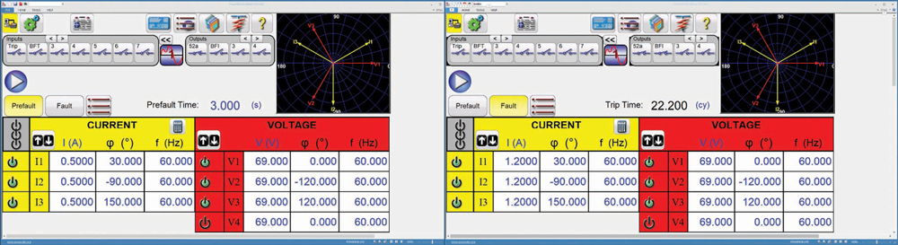
To test BFP logic implemented via a single multifunction relay, we instead run two tests and subtract the time of one from the other. First, we get trip time by again utilizing a pre-fault/fault test starting timing on fault injection and stopping when the relay issues the breaker trip signal, which we will record as the trip time (Figure 6). Next, we utilize this same pre-fault/fault test, but we stop the test based on the BFT output signal from the relay rather than the breaker. We record this result as the BFT Time.
We now simply subtract the trip time from the BFT time to calculate the actual breaker fail time delay and compare the result to the expected 62 BFTD and ensure it is within allowable tolerances.
Dynamic Testing
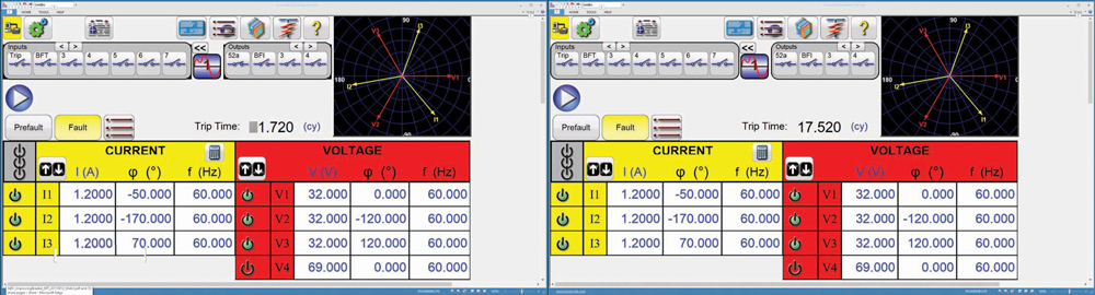
When testing a multi-function relay, testing BFP logic with a single dynamic test rather than the two-step process above is often preferred. In this case, we need a more modern test set with a state sequence tool and multiple binary inputs to sense the different trip signals. In this example, we use a five-state test sequence (Figure 7) to collect all the timings we are interested in as part of a single operation.
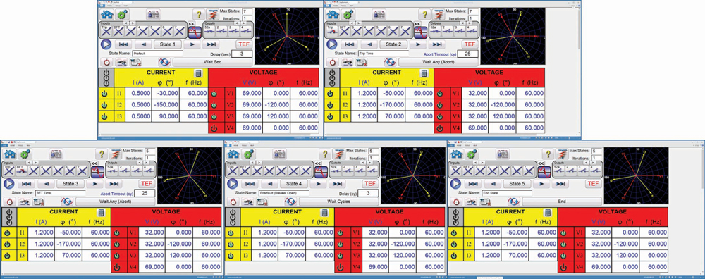
During this test, it is again critical to ensure that if a 52a status is used in the scheme, it is simulated in the appropriate position in each state. Here, our first state is a simple pre-fault state, with healthy values for the system, and set to move to the next state in the sequence simply based on a preset time.
Next, the second state will measure the trip time by applying a fault and timing until we receive the breaker trip signal from the relay, at which point we advance to the next state. This third state continues applying the same fault but is now monitoring for the BFT output coming back from the relay. The fourth state is simply a postfault state simulating the final breaker opening time following a breaker failure trip, again advancing to the next state based on a simple wait time rather than any signal from the relay. Applying the process to the end state brings the test to a close.
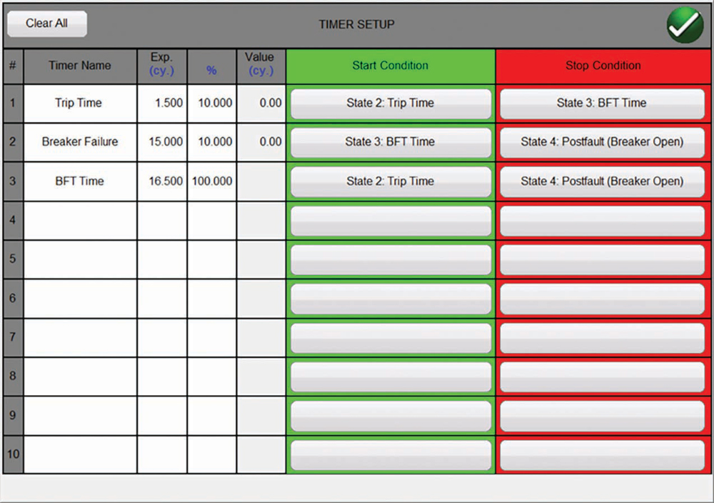
If we set up the monitoring timers appropriately, this sequential test simulating a single fault event (Figure 8) allows us to measure trip time (from the start of State 2 to the start of State 3), and BFT time (from the start of State 2 to the start of State 4) as we did in the previous manual test, but also to directly time rather than calculate breaker failure time delay (from the start of State 3 to the start of State 4). This simple dynamic test can be set up in advance and used repeatedly, and it avoids small differences that may occur in response times during multiple separate tests.
End-to-End testing
Testing a remote breaker failure scheme sometimes involves employing end-to-end testing techniques. An explanation of this is beyond the scope of this article, but more information about end-to-end testing can be found in S. Kuber and A. Gonzalez.
CONCLUSION
Breaker failure protection is essential for maintaining the stability, reliability, and safety of power systems. It ensures that faults are effectively isolated, equipment is protected, and the power system operates within safe parameters, thereby enhancing overall operational efficiency and reliability.
While the fundamental principles of breaker failure protection are similar in transmission and distribution systems, the specific implementation details, complexity, and priorities differ significantly due to the distinct characteristics and requirements of each system.
By implementing these breaker failure protection schemes, power systems can ensure that faults are cleared promptly even in the event of a primary breaker failure, thereby maintaining system stability, protecting equipment, and enhancing overall reliability.
REFERENCES
[1] G. Hataway, J. Ellison, and M. Thompson. “Improving Breaker Failure Protection for Generator Applications.” Published in Synchronous Generator Protection and Control: A Collection of Technical Papers Representing Modern Solutions, 2019. Accessed at https://selinc.com/api/download/10261/. [2] E. Csanyi. “The Philosophy of Breaker Failure Protection.” Accessed at https://electrical-engineering-portal.com/the-philosophy-of-breaker-failure-protection. [3] IEEE. IEEE Std. C37.119–2016, IEEE Guide for Breaker Failure Protection of Power Circuit Breakers. Accessed at https://standards.ieee.org/ieee/C37.119/5746/. [4] S. Kuber. “End-to-End Testing for Line Differential Protection,” NETA World, Winter, 2019. Accessed at https://netaworldjournal.org/end-to-end-testing-for-line-differential-protection/. [5] A. Gonzalez. “Distribution Automation Networks – Application & Testing,” NETA World, Summer 2023. Accessed at https://netaworldjournal.org/distribution-automation-networks-application-testing/.
Jacob Loyd is a Relay Applications Engineer with Megger’s TSG Group. His responsibilities include providing technical support and training on Megger’s relay test equipment and Baker motor testing equipment, with particular expertise in the testing and calibration of electromechanical relays. Previously, Loyd spent 16 years at Palo Verde Nuclear Generating Station, with 10 years in electrical maintenance, working on everything from large power transformers to motor control circuits, and six years in the Protective Relaying and Controls Group, helping with the transition from older electromechanical relaying to modern microprocessor-based solutions.

Mike Wilson is based in Houston as the South Texas Area Technical Sales Representative for Megger. He previously served as a Senior Relay Applications Engineer for Megger. Wilson’s professional experience includes P&C design, Lead Commissioning Engineer, and NERC Compliance Manager. He earned a BS in electrical engineering from Missouri University of Science & Technology and an MS in management from Indiana Wesleyan University. Wilson is a student pilot, an IEEE member, and a member of the Experimental Aircraft Association (EAA) Chapter 309.

Abel Gonzalez is a Senior Relay Applications Engineer with Megger. His research areas are the analysis operation, control, and protection of electric power systems. Gonzalez was previously a Professor at the Universidad Central de Las Villas, Cuba; head of the marketing department for the Cuban Telecommunications Company; and a Design Engineer for Arteche Medición y Tecnología in Zapopan, Jalisco, Mexico, and Curitiba, Brazil. He is currently a member of the IEEE-PSRC. Gonzalez earned a BS and MSc in electrical engineering from the Universidad Central de Las Villas, Cuba.