

Motors and generators are often critical components of electrical systems. They are used to automate numerous industrial processes, circulate liquids for cooling and lubrication purposes, and generate electricity to name only a few applications. If, for any reason, there is an unplanned interruption of these processes due to the failure of one of these rotating machines, the resulting damage, downtime, and inability to perform crucial work can have significant and costly repercussions. For this reason, a great deal of emphasis has been placed on ways to ensure the health of rotating machinery as well as other electrical and power system apparatus.
The failure of rotating machinery can often be attributed to the degradation and/or contamination of the insulation that separates electrically energized components from one another and from ground. Electrical insulation is a sensitive and integral part of rotating machinery and is therefore of undeniable importance to the continued health and operation of these machines.
One way to evaluate dry-type and solid insulation is to perform AC insulation tests and use testing techniques to quantify losses in electrical insulation. The remainder of this article will describe power factor and power factor testing techniques and how they can be used to provide valuable information for triggering decisions related to testing and maintenance, and perhaps even for asset replacement planning.
POWER FACTOR (DISSIPATION FACTOR) TESTING
Although not always required for rotating machines that are rated for less than 6 kV, one of the tests often performed on rotating machines is commonly referred to as a power factor test or a dissipation factor (tan δ) test. These measurements are calculated differently using complementary angles as shown in Figure 1.

However, for modern stator winding insulation systems, power factor and dissipation factor are often used interchangeably. Power factor and dissipation factor are unitless measurements of electrical losses that occur in insulating materials and are commonly reported in terms of percentage. These tests are considered diagnostic in nature due to their ability to trend measurements over time and provide insight regarding changes in the insulation of electrical apparatus such as motors and generators.
An ideal insulator is a perfect capacitor that has no losses; current leads voltage by 90 degrees. In this case, the power factor or the cosine of the angle between voltage and current would be zero (0). However, there is no such thing as a perfect capacitor (insulator). There will always be some small amount of leakage current through the insulating material. Coil systems such as those found in electric motors have inherent losses causing both capacitive and resistive current flow. For this reason, a realistic and desirable power factor value or dissipation factor can be small in a good insulating system, but it can never equal zero (0).
One reason to conduct power factor or dissipation factor tests on rotating machines is to assess the effects of voids and void formation associated with solid and dry-type insulation. The tests can assess the manufacturing process involving these insulating materials and evaluate the insulation over the life of the machinery. Ionization of these voids ultimately equates to increased dielectric losses and deterioration of the insulation over time.
IEEE Std. 286-2000, IEEE Recommended Practice for Measurement of Power Factor Tip-Up of Electric Machinery Stator Coil Insulation refers to these losses as corona discharges. In this case, a corona discharge would refer to the partial breakdown of the insulation as a result of ionizing gaseous voids beyond a critical voltage gradient. An overall power factor measurement on winding insulation can indicate the progression of this type of partial discharge associated with increasing deterioration of insulation due to aging or the ingress of moisture and other contaminants.
Excluding other techniques that may involve power factor measurements, these tests are performed:
- Off-line
- With the stator winding isolated so that each phase can be tested independently
- At a single voltage not to exceed the line-to-neutral rating of the apparatus
- At power system frequency.
Tests will be performed on the insulation between each phase of the motor stator and ground, as well as the interwinding insulation between phases of adjacent windings (Figure 2).

When applied to large, highly capacitive rotating machinery, the use of a resonating inductor may be required to extend the charging current capability of the test equipment. This effectively helps overcome what might otherwise be a limiting factor to attaining the recommended test voltage.
Performing PF tests at the same voltage every time the test is performed over the life of each specific apparatus allows results to be trended and compared in such a way as to differentiate between gradual changes and those that might be considered more significant. Gradual changes often relate to a normal aging process, while more significant changes can result from unusual stresses to the insulation. A good analogy would be a person who grows old gracefully as opposed to someone who falls and is injured. Being able to identify changes as well as the severity of those changes can provide predictive insight into preventing unplanned downtime and/or impending failure.
POWER FACTOR TIP-UP TESTS
While power factor testing is applicable to almost any type of electrical insulation, power factor tip-up tests are especially applicable to dry-type insulation such as that found in some smaller distribution transformers as well as in rotating machinery. Performing power factor testing on motor windings can serve as a baseline measurement for trending purposes over time. A powerfactor tip-up test shows the variation of dielectric losses over a range of voltages and is widely used to identify and even sometimes characterize voltage dependencies in winding insulation.
More specifically, excluding outside influences, an oil or liquid-filled apparatus is expected to maintain the value of dielectric losses throughout the range of voltages up to and including the rated line to neutral voltage. However, solid/dry insulation has proven to be more voltage-dependent due to the nature of these materials, even within the rated line to neutral range of operation. A great deal of information regarding this topic is available in the IEEE Std. 286-2000.
To better understand the value of power factor tip-up, let’s define what it is and how it can complement a standard power factor test. The electrical power industry offers the following definition of power factor tip-up in IEEE Std. 100-2000, The Authoritative Dictionary of IEEE Standards Terms:
The difference between power factor measurements at two different designated voltages applied to an insulation system, other conditions being constant.
- The first power factor measurement is often conducted at approximately 25% of the rated line-to-neutral voltage. This should be a low enough voltage that partial discharge has not yet begun to occur.
- A second power factor measurement is performed at 100% of the rated line-to-neutral voltage.
Since solid/dry type insulating materials are proven to be more voltage-dependent than other types of insulation, it is much more likely that partial discharge will begin to occur, producing increased losses and higher values of power factor. This is where power factor tip-up testing becomes a more valuable indicator regarding the health of the insulation.
The number representing tip-up is derived by subtracting the power factor value at the lower test voltage (~25% of VL-N) from the power factor value at the higher test voltage (~100% of rated VL-N). Refer to Table 1.

PF TipUp = PF (@ 100% of L-N voltage rating) – PF (@ 25% of L-N voltage rating)
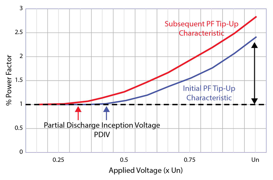
Two significant factors to observe are the tip-up value and the lowest value of the voltage at which power factor begins to increase. This point is often referred to as partial discharge inception voltage (PDIV). Determining an inception voltage by plotting power factor measurements over a range of applied voltages is not a precise method of determining PDIV, but it can offer general insight into when insulation is beginning to deteriorate and perhaps when a more precise method of determining this value might be warranted.
Greater resolution of the voltage dependency of insulation can be observed by plotting power factor versus applied voltage at additional points between 25% and 100% of rated line to neutral voltage. An example of what might be observed can be seen in Figure 3, as these additional values of power factor are plotted in relation to their respective line to neutral voltages.

CONCLUSION
The amount of increase in power factor value as a function of voltage corresponds to the dielectric losses that are somewhat characteristic of dry-type insulation. The power factor tip-up characteristic serves as another means by which electrical insulation can be evaluated in terms of voltage dependency and what that may indicate regarding age, contamination ingress, and deterioration.
Additionally, plotting power factor values at multiple applied voltages may also give an indication as to the voltage at which partial discharge begins to occur (PDIV) and how it changes over time. Figure 4 illustrates deterioration within the insulating system as seen by the increased value of power factor tip-up. If we are also monitoring the plotted characteristic of power factor over a range of voltages, the voltage at which losses begin to increase can serve as another reference to the degree of insulation deterioration over time.
There is much more to know and understand about the electrical testing techniques that can and often are applied to various types and applications of electrical insulation. The goal of this article has been to show how power factor tip-up tests can be a valuable tool in identifying and characterizing voltage dependencies of dry-type electrical insulation in rotating machinery. These tests can indicate whether insulation is changing in ways that are expected and associated with normal aging or in ways that are more dramatic and potentially alarming.
Additionally, we’ve shown how these changes characterize the deterioration and/or contamination of insulation found in rotating machinery. Trending power factor and power factor tip-up results can provide insight into planned mitigation of much more costly failures. As insulation ages and begins to increase in voltage dependency, as dry-type insulation often does, these tests can potentially serve as triggers for more frequent testing, the performance of actual partial discharge tests, and perhaps decisions regarding the timing of other asset management decisions.
REFERENCES
IEEE. IEEE Std. 286-2000, IEEE Recommended Practice for Measurement of Power Factor Tip-Up of Electric Machinery Stator Coil Insulation, pp. i–29, 2001,
doi: 10.1109/IEEESTD.2001.92415.
IEEE. IEEE Std. 100-2000, The Authoritative Dictionary of IEEE Standards Terms, Seventh Edition, pp. 1–1362, 11 December 2000, doi: 10.1109/IEEESTD.2000.322230.
Duarte, Eileen. “Power Factor Testing of Stator Winding Insulation: Understanding the Test Technique and Interpretation of Results,” NETA World, Summer 2004.

Bret Hammonds currently serves as the Director of Application Resources for Protec Equipment Resources, LLC. He has over 30 years of experience in testing power system apparatus within the electrical power industry. He is an IEEE member and was previously a voting member of the ASTM D27 committee on electrical insulating liquids and gases. In addition to having performed and/or directed field testing services in utility, commercial, and industrial applications, Bret has spent a large portion of his professional career in technical support roles such as his position as a senior applications engineer for a manufacturer of electrical test equipment. Bret has been published in IEEE transactions journals for his work in the area of low-voltage circuit breaker testing. He has also been recognized for his technical presentations at industry conferences such as the Transmission and Substation Design and Operation Symposium (TSDOS) and NETA’s PowerTest conference. Bret holds a BS in electrical engineering technology from Texas Tech University and an MBA from the University of Phoenix.