

Traditional line protection incorporates elements in the phasor domain. Phasor-based line protection uses a full cycle of data and is subject to CT accuracy limitations, limiting operating speed and fault location accuracy.
However, new advances in protective relay technology have facilitated the introduction of relays that operate in the time domain. By detecting and time-stamping the arrival of traveling waves at each terminal, these devices employ peer-to-peer communication to make trip decisions and calculate fault location. These new devices are free of the inherent delay of phasor-based relay algorithms and the accuracy limitations of traditional fault current measurement, so trip times less than 1.5 ms and fault location to within one structure have been observed.
This article provides an overview of traveling wave and superimposed component distance protection and presents a trial project of the technology on the Salt River Project (SRP) system.
SITE SELECTION
The SRP selected the line location to install, monitor, and evaluate this new technology on a trial basis. When testing any new system, the desire is to maximize the number of all possible types of operations during the trial period. SRP chose to deploy the new technology for this evaluation on an 8.49-mile, overhead 69-kilovolt sub-transmission line between the Dinosaur and Micromill One substations southeast of the Phoenix metropolitan area. Located in an area of undeveloped desert landscape, this line experiences persistent wildlife activity, and the lack of surrounding structures increases the exposure to seasonal thunderstorm activity.
Equally important was choosing a transmission line constructed with optical ground wire (OPGW). Taking advantage of differential protection in the time domain requires a direct fiber link between relays to achieve communication data rates that approach the speed of light, which is a common basis for measuring traveling wave velocities. OPGW is available in the SRP service territory. However, the allocation of this medium is dominated by business purposes other than system protection. Therefore, acquiring a second pair of these fibers to use between the two ends of the line beyond the existing multiplexed pair that already carries all other station-to-station traffic required additional justification and approval.
DESIGN AND INSTALLATION
This trial relaying was designed systematically to operate in parallel with the line’s existing phasor-based protection using 11TD time-domain relays (Figure 1). This allows direct comparison with the behavior of the devices already deployed (87L — a pair of multi-function differential relays using multiplexed communications, and 21L — local impedance-based distance relays) during post-event analysis. Since this installation is for testing purposes, the time domain relay trip outputs were not connected to the circuit breakers’ trip circuitry. Not only does this prevent any unexpected operations from disturbing an in-service line, but it also allows settings changes to be made remotely without the need for test permitting or local device isolation.
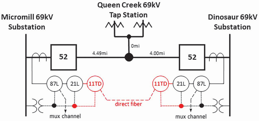
Figure 1: Time Domain Relay Installation Single-Line Diagram
Using a short-circuit program, a system-equivalent model was created for the protected line. Six elements were evaluated closely to allow optimal protection testing and fault locating. The first two settings — the phase and ground overcurrent supervision thresholds — were calculated by simulating different types of faults at the remote-end bus. These values were coordinated to be between the lowest possible fault and the maximum possible load expected on this transmission line. These elements establish a threshold to supervise the traveling wave relay elements to prevent mis-operation during non-fault related system events.
Next, the forward- and reverse-directional elements were scrutinized. These additional impedance thresholds will supervise the line distance and differential elements within the 11TD. Using the aforementioned system-equivalent model again, the forward setting was calculated as 30% of the minimum positive-sequence impedance behind the local bus. The reverse setting was then simply calculated as 30% of the protected line’s positive-sequence impedance. These calculations provide torque control with a conservative safety margin for any system calculation errors.
The incremental distance element zone setpoints were set based on the utility’s standard convention. Accounting for maximum expected instrument transformer and line modeling errors, 80% for phase and 70% for ground faults were set. Although the source impedance ratio (SIR) at each end of the line was not used to determine the reach settings, it was calculated here for informational purposes. Based on classic SIR calculations, the line appears long from the transmission station end of Dinosaur Substation (SIR < 0.5) but is medium length from the distribution bus at the Micromill One Substation (0.5 < SIR < 4). This ultimately affects the operating time of the time domain distance function, but with both being relatively small, the relay is expected to operate faster.
The final two settings have to do with line propagation velocity. Fault location using traveling waves (TWs) is determined by the equation:
(1)
where:
LL is the total line length
local is the time the TW arrives at the local end
tremote is the time the TW arrives at the remote end
vp is the propagation velocity
The static values that can be programmed into the device are LL (already known) and vp (to be determined experimentally). Additionally, at each end of the line, current transformers will translate the TW signal entering secondary cabling before finally arriving at the 11TD relay. This cabling is assigned a fractional value of the speed of light based on its physical attributes, representing the additional delay the TWs will be subjected to. Seemingly minor, this setting can account for substantial errors in fault location.
Once device installation was completed, a power system switching procedure was followed to allow capture of a high-speed traveling wave event that could be analyzed to determine the subject line’s specific vp. Initially assuming that it would be equivalent to 98% of the speed of light allowed for a calculated estimate of the anticipated time difference between the TW sent from closing one end of the line (t1local) and the reflection received from the open opposite end of the line (t2local). Manipulating (1) provided:
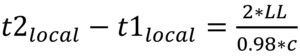
(2)
where:
c is the speed of light
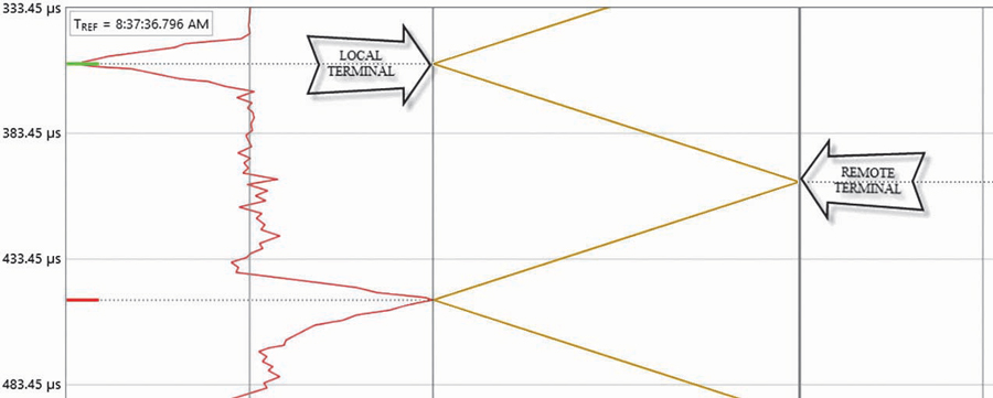
Figure 2: Bewley’s Lattice Diagram of Propagation Test Results
The resulting value for our 8.49-mile line was 93 s, which is close to the time difference between the negative TW launching peak and the positive TW reflection peak seen in the Bewley diagram in Figure 2. Utilizing the actual time difference found experimentally and substituting it into (3) provided a final value for vp:
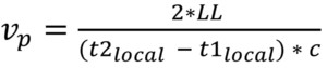
(3)
It is interesting to note the polarities of the traveling waves launched by each phase of the breaker closing, as seen in Figure 3. A positive voltage waveform will result in a current signal’s TW having a positive polarity; a negative voltage waveform will likewise result in a negative-polarity TW. The reflection of the TW off the open end of the line results in a perfect inversion due to its infinite impedance. Similarly, a transformer located at the end of the line, which would have a higher characteristic impedance than the transmission line, would have also inverted the reflected TW. However, a line tap produces a minor reflection of the same polarity (not inverted) due to the parallel impedance reducing the line’s effective characteristic impedance. Although there is a line tap along the subject line, the reflections from it were not significant.
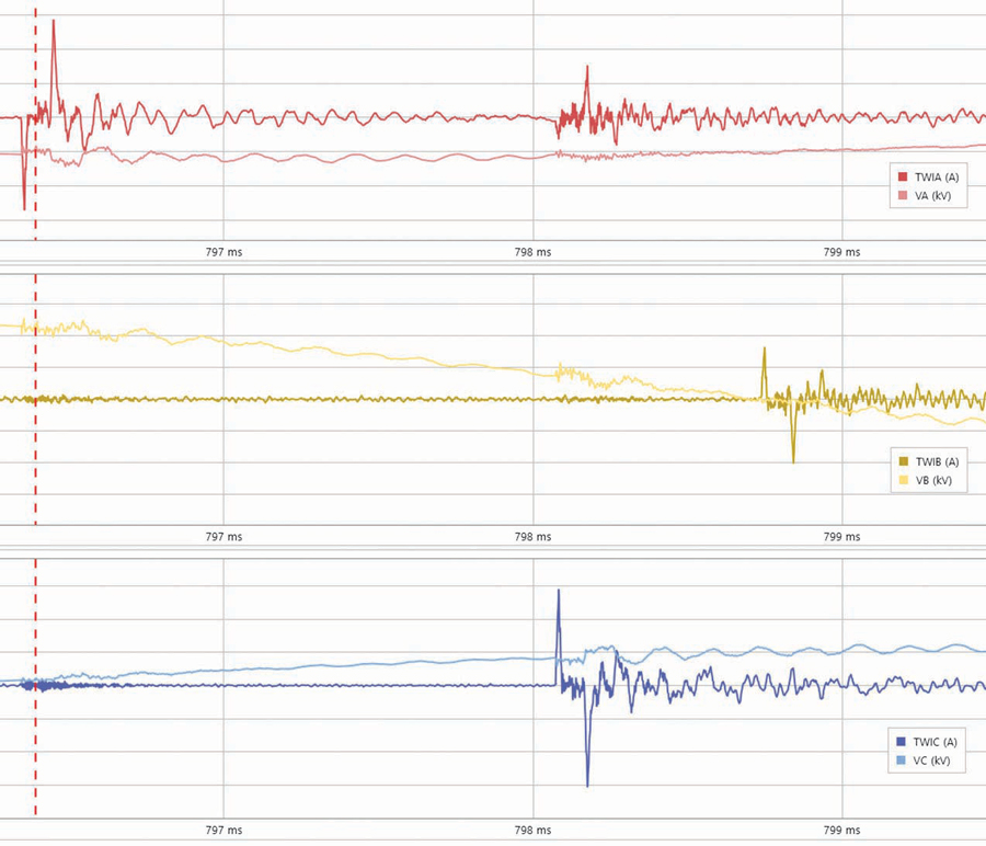
Figure 3: Time Domain Plot of Propagation Time Test
In all cases, the reflection coefficient seen at the end device can be expressed as in (4):
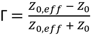
(4)
where:
Z0,eff is the effective characteristic of the object connected to the line causing the TW reflection
Z0 is the characteristic of the subject line itself
TESTING
Onsite field testing was desired and undertaken to establish in-zone fault detection performance, out-of-zone fault descrimination, and operation of the backup time domain distance protection. Specialized end-to-end testing was selected as the test method.
Of course, testing relays operating in the time domain presents a number of challenges:
- First, since testing without disturbing relay settings was desired, realistic traveling waves and 60 hz components must be applied to both relays simultaneously.
- Second, when transitioning from prefault conditions to fault conditions, source impedance must remain constant.
- Third, test signal injection timing at the local and remote ends must be extraordianarily precise, as each 1 nsec of timing errror results in a fault location error of roughly 1 foot.
- Finally, the simulated traveling waves must possess suitable rise times and amplitudes in order to pass through the relay’s traveling wave filter.
Test Software, Hardware, and Connections
The protected line was modeled in the test software by graphically describing the system under test (Figure 4) and then entering system voltage, system frequency, line impedances, source impedances, line length, CT polarity, and travelling wave propogation time.
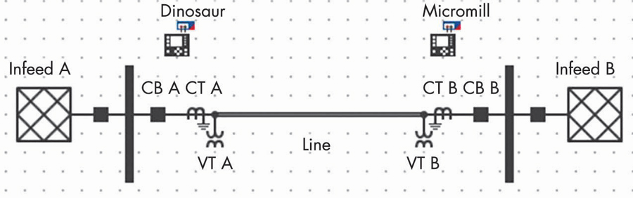
Figure 4: System Model for Commissioning Test
From this infomation, the test software calcuates traditional 60 hz test quantities, traveling wave pulse polarity, and injection time for each test case. The desired commissioning test cases included in-zone phase-to-phase and phase-to-neutral faults, as well as out-of-zone phase-to-phase and phase-to-neutral faults.
At each end of the line, a test set and travelling wave injection hardware were connected to the relay test switches via standard test-switch adapters. A standard relay test set provided test currents and voltages in the power frequency range. An accessory device was used to generate current and voltage channel traveling waves. The accessory device currents were connected in parallel with the relay test set currents providing a test input equal to the sum of the 60 Hz and traveling wave test signals. The voltage signals from the relay test set were connected in series with the traveling wave accesory voltage signals, providing a signal equal to the sum of power frequency and traveling wave voltages. Relay operations were measured by monitoring the relay output contacts with the relay test set. A separate IEEE 1588 grand-master clock provided time synchronization for the local and remote test sets.
Communication of test-case parameters and time-synchronization instructions between the local and remote terminals was conducted via a 4-G cellular modem.It should be noted that since the actual timing of the test signals is synchromized by a GPS at each end of the line, the communication speed of test parameters is not critical.
Once the test equipment was installed, communication and connections were verified by simulating normal line load flow and verifying the relay metering against the programmed inputs.
Fault Simulation of the Traveling Wave Differential
For the traveling wave differential element to operate during testing, several conditions must be met:
- The relay communication channel and GPS clocks are healthy.
- Protection is armed by simulating a normally energized line with no loss of potential, open pole, normal frequency, and no existing fault.
- At simulated fault inception, incremental quantity overcurrent supervision condition is met by accurately simulating fault conditions in the power frequency range.
- Current traveling waves meeting the waveshape criteria of the travelling wave filter are recieved at both ends within the programmed propogation time
Results
To test the operation of the installation, B-C-N, C-A-N, A-B-C-N, and C-A faults were simulated at various points on the protected line. The traveling wave differential protection operated in all cases. Traveling wave element trip times ranged from 1.0 ms to 2.3 ms. Fault location error, measured by comparing the simulated fault position and the reported fault location by the relay, was less than 20 meters in all test cases.
To test selectivity, faults were also simulated on the adjacent buses. This simulation causes the current traveling waves sent to the relay adjacent to the fault and the relay on the opposite side of the line to have opposite polarities due to connected CT polarization. The resultant restraint quantity would be large, and the operate quantity would be small, resulting in no traveling wave differential element operation. As there are no parallel lines in this application, this would be sufficient to block the traveling wave differential. Note that additional supervisory logic is implemented for applications with parallel lines.
Tests simulating faults on either bus adacent to the line resulted in no traveling wave differential element operations.
Fault Simulation of the Incremental Quantity Distance Element
To test the operation of the traveling wave differential element, several conditions must be met:
- Test signals must be consistent with line and system impedances.
- Protection is armed by simulating a normally energized line with no loss of potential, open pole, normal frequency, and no existing fault.
- Incremental quantity overcurrent supervision condition is met by accurately simulating fault conditions in the power frequency range.
- Traveling wave protection is blocked.
- Simulated fault impedance is inside the Zone-1 reach setting.
Procedure and Results
As the traveling wave differential is substantially faster than the incremental distance, the traveling wave differential must be blocked to test the incremental distance element. This was acomplished by changing the fault inception angle to the positive zero crossing, which results in no traveling waves generated by the simulation. The incremental element was tested with simulated phase-to-neutral and phase-to-phase faults around the programmed reach settings, 0.8 pu and 0.7 pu, respectively. The incremental distance protection operated in 2.9 ms to 4.2 ms. As with other types of distance protection, some under-reaching was noted with higher source impedance ratios.
REAL WORLD EXPERIENCE
The Dinosaur-Queen Creek-Micromill One transmission line experienced a C-phase-to-ground fault in July 2018. The event was caused by multiple foil balloons bridging the C-phase insulator and the pole ground conductor. When the line was physically inspected later, field crews confirmed evidence of arcing at both of these locations on the transmission structure (Figure 5). This structure is located approximately 6.45 miles from the Dinosaur Substation end of the line.
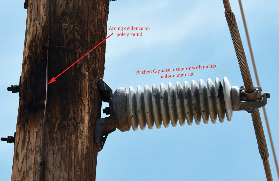
Figure 5: Actual Line Fault (07/18)
The 11TD relay record correctly indicated a C-phase-to-ground fault for this incident. The travelling wave fault-locating feature calculated a distance of 6.47 miles from Dinosaur Substation. When compared to the actual location reported by crews, the relay’s number was within 100 feet of the actual event. Furthermore, closer manual examination of the waveforms captured within a Bewley’s lattice diagram provided a marginally closer distance (Figure 6).
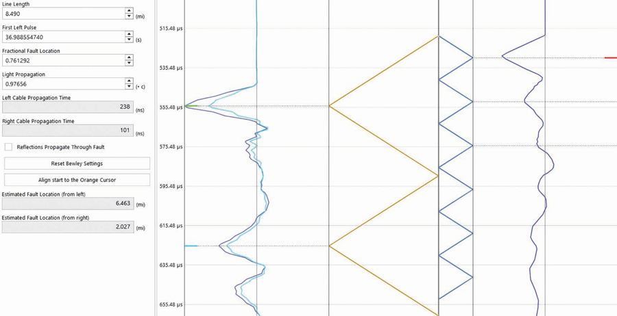
Figure 6: Bewley’s Lattice Diagram from 07/18 Relay Fault Record
In addition to reviewing the 11TD records, engineering personnel also extracted records from the paralleled tripping relays. The line differential relay (87L) reported a fault distance of 5.95 miles based on its traditional impedance-based calculations. Although we are dealing with a short line, this still represents a difference of eight transmission structures between the reported and the actual fault location. This clearly demonstrated the 11TD device’s superior fault-locating capabilities.
The 11TD and 87L operating speeds were also compared for the event. Traveling wave directional fault detection in the 11TD relay occurred in under 0.1 ms, with the incremental quantity directional element picking up in under 1.5 ms. The operating speed of the 11TD relay was measured at approximately 0.9 ms on the Micromill One end (which was less than a third of the distance to the fault location at 2.04 miles) and 2.1 ms on the Dinosaur end. As seen in Figure 7, these times are calculated between the traveling wave disturbance detector and trip output assertion. The incremental quantity distance elements were slower and did not operate for this fault.
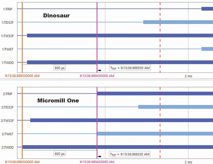
Figure 7: Sequence of Events Plot for 7-18 Fault
In contrast, the phasor-based 87L relay had considerably longer operating times. Zero- and negative-sequence directional elements picked up in just under 9 ms. The overall operating speed of the relay was again determined between its disturbance detection and the first trip output assertion. In this case, the impedance-based protection narrowly beat the differential on the Micromill One end, which was within the instantaneous Zone-1 ground operating region, set to 70% of the line impedance, operating in under 15 ms, as seen in Figure 8. The Dinosaur end called for a differential trip in under 18 ms, which would finally complete the line clearing.
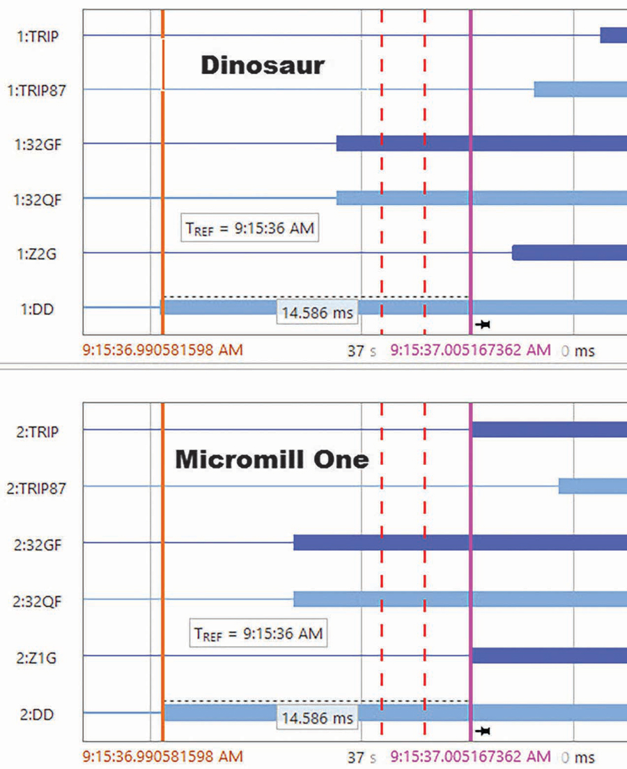
Figure 8: Sequence of Events Plot #2 for 7-18 Fault
Therefore, the 11TD dominated its relaying predecessor with significantly higher operating speeds, clocking in at 1/8th of a power-system cycle for total line tripping. The 87L allowed more than a cycle to elapse before calling for both ends to open.
CONCLUSION
In this application, the traveling wave line differential relay offered increased tripping speed and substantially more accurate fault location.
REFERENCES
E.O. Schweitzer III, A. Guzman, M.V. Mynam, V. Skendzic, and B. Kasztenny. “Locating Faults by the Traveling Waves They Launch,” 40th annual Western Protective Relaying Conference, Spokane, Washington, October 2013.
R. James and S. Hayes. “Utility Experience with Traveling Wave Fault Locating on Lower Voltage Transmission Lines,” 45th annual Western Protective Relaying Conference, Spokane, Washington, October 2018.
IEEE Std.C37.113, IEEE Guide for Pr otective Relay Applications to Transmission Lines.
 Faris Elhaj joined OMICRON electronics in 2018 as a Training and Application Engineer based in Houston, Texas. His focus areas include protection and power utility communications (PUC). Faris started his career in protection and control (P&C) in 2012, working for GE in a variety of roles, delivering training on protection concepts and providing application support on Multilin relays and has executed many P&C service projects, conducting installation and commissioning activities for utilities and industrial plants. Faris received his BS and MS in electrical engineering from McMaster University in Hamilton, Ontario.
 Scott Cooper is a Training and Application Engineer with OMICRON electronics. He has over 17 years of experience in a variety of high-intensity sales, application engineering, and training roles while working for Manta and Beckwith, mainly selling and supporting P&C test equipment and systems. Scott is an active member of IEEE PES committee serving many PSRC working groups. While serving in the United States Navy, he was a qualified reactor operator and shutdown reactor operator, a qualification board member, a Reactor Plant Drill Team member, and a Reactor Training Division Instructor.
 Anthony Sivesind has 18 years of experience in the utility industry and has worked in a variety of roles during his tenure at Salt River Project, including designer, engineer, and project manager of major substation construction and transmission jobs, new protection and control initiatives, and standards development and implementation. He is presently an Executive Engineer in the Protection, Automation, and Control Strategy Department, where he can focus on research and development initiatives to efficiently protect and control the grid in support of SRP grid modernization. Anthony received his BS and MS in electrical engineering with an emphasis in mechatronics and alternative energy from Arizona State University.
Francisco J. Sanchez is a Generation Engineer supporting Salt River Project generation facilities. He received his BS in electrical and computer engineering from New Mexico State University.