

In Part 1 of our three-part series on acceptance and maintenance testing for medium voltage electrical power cables, we reviewed cable construction and cable aging characteristics and started our discussions on cable testing options and philosophies. In Part 2 of this article, we move away from undervoltage testing and explore high potential testing techniques.
HIGH POTENTIAL TESTING PERFORMED WITH DIRECT CURRENT
For years, high-voltage direct current (DC) testing has been the traditionally accepted method for judging the serviceability of medium-voltage cables. Direct current tests have worked well for conducting high potential and condition assessment tests on paper-insulated, lead-covered (PILC) cable, and when plastic-insulated cables were first introduced in the 1960s, DC continued to be the preferred method.
As time moved on, plastic-insulated cables became more abundant and began showing the effects of service age. Direct current continued to be the dominant test, but concerns began to grow over its effectiveness. In the early 1990s, reports began to surface indicating that DC high potential testing could be at fault for latent damage experienced by extruded medium-voltage cable insulation (cross-linked polyethylene and ethylene propylene rubber). After receiving these reports, the Electrical Power Research Institute (EPRI) funded a study related to cross-linked polyethylene (XLPE) cables. This study (EPRI Report TR-101245) yielded the following conclusions regarding XLPE cable:
- DC high potential testing of field-aged cable reduces its life.
- DC high potential testing of field-aged cable generally increases water tree growth.
- DC high potential testing before energizing new medium-voltage cable doesn’t cause any reduction in cable life.
To better understand the conclusions of the EPRI study, it is beneficial to again review the aging characteristics of extruded dielectric cables and the process of water treeing.
Water Trees
Water trees begin to form when a cable is exposed to water and normal operating voltage over an extended period of time. Electrical forces acting on water molecules — electrophoresis — at a microscopic point within the insulation increases the separation between polymer units. These water droplets become oriented into a chain-like channel. The result is a sharp electrode, producing highly localized stresses. Once treeing is initiated, electrical stress exists from the base of the tree channel to its extremity.
When high levels of DC voltages are impressed on solid extruded polymeric materials, their good electrical insulation properties become degraded. For example, trapped or low-mobility electrically charged species within the bulk can give rise to space charge, resulting in localized electric stress enhancement. This can cause further concentration of charge and accelerate electrical ageing. The water tree part contains more ionic impurities than the sound part. It is therefore likely that in XLPE cable under DC voltage stress, space charges are formed in the water tree region and its vicinity, promoting an increase in water tree growth and reduced service life.
In 1996, a few years after the EPRI reports, the insulated conductor industry determined that DC high potential testing of plastic (XLPE) insulation systems — in the cable factory as a routine production test or after installation as a high-voltage proof test — was detrimental to the life of the insulation. EPRI therefore discontinued recommending DC testing for plastic (XLPE) insulation systems.
IEEE Standards
In 2001, IEEE released IEEE Std. 400-2001, IEEE Guide for Field Testing and Evaluation of the Insulation of Shielded Power Cable Systems. The new standard includes statements such as:
Testing of cables that have been aged in a wet environment (specifically XLPE) with DC at the currently recommended DC voltages may cause the cable to fail after they are returned to service. These failures would not have occurred at that point in time if the cables had remained in service and had not been tested with DC.
This standard also indicates that other testing has shown that “even massive insulation defects in extruded dielectric insulation cannot be detected with DC at the recommended voltage levels.”
Current versions of most industry recommendations no longer include DC high potential testing of extruded cables (XLPE and EPR) as a maintenance test. Those that still do have all reduced the recommended test duration from 15 minutes to only 5 minutes. None endorses DC high potential testing as a factory test for extruded cables, but most documents continue to include DC high potential testing as an acceptance test on newly installed extruded cable. These industry recommendations and guides also no longer endorse DC high potential testing as a maintenance test for extruded cables that have been in service for more than five years.
Laminated insulation systems are not subject to the same aging characteristics as XLPE and EPR. Therefore, DC testing is more accepted for acceptance and maintenance testing of paper-insulated, lead-covered cable (PILC). Keep in mind, however, that the test has limitations. DC leakage can be affected by external factors such as heat, humidity, and water level if unshielded and in ducts or conduits. It can also be affected by internal heating if the cable under test has recently been heavily loaded. These factors make comparisons of periodic data obtained under different test conditions very difficult. In practice, the shape of the leakage curve, assuming constant voltage, is more important than the absolute leakage current of a go-no-go withstand test result.
In 2021, IEEE Std. 400.5-2021, IEEE Guide for Field Testing of DC Shielded Power Cable Systems Rated 5 kV and Above with High Direct Current Test Voltages, was released. The recommended practices and procedures for direct voltage acceptance and maintenance testing of shielded, insulated power cable systems rated 5 kV and above for DC service are presented in this new guide. The guide applies to all types of power cable systems that are used for the transmission of DC voltages and can include laminated or extruded cables designed for DC service.
In this new guide, we see recommended test voltages of 1.45 times the nominal voltage rating of the cable and test durations of 15 minutes for high-voltage cable. The guide also emphasizes safety related to high-voltage DC testing and provides several warnings on the importance of sufficiently long periods of time for grounding after testing.
HIGH POTENTIAL TESTING PERFORMED AT POWER FREQUENCY
As the name implies, this test method is based on using alternating current (AC) at the operating frequency (50/60 Hz) of the system as the test source. This method has the advantage of stressing the insulation comparably to normal operating conditions. Power frequency high potential testing is most commonly conducted by cable manufacturers. The withstand testing determines the dielectric strength of the insulation system and identifies gross defects. The test looks at the bulk of the insulation and renders a pass or fail conclusion. A further advantage of power frequency testing is that it allows partial discharge and dissipation factor (tan δ) testing for diagnostic purposes.
It should be noted that power frequency testing methods can be categorized as withstand or diagnostic.
- In withstand testing, insulation defects are caused to break down (fault) at the time of testing. Faults are repaired or removed, and the insulation is retested until it passes the withstand test. The withstand test is considered a destructive test.
- Diagnostic testing allows the relative condition of degradation of a cable system to be identified and establishes, by comparison with figures of merit, whether a cable system can or cannot continue operation. Diagnostic testing is considered nondestructive.
As a field test, power frequency testing suffers a serious disadvantage since at increased voltage levels, the test sets require heavy, bulky, and expensive transformers. Field portable AC high potential test sets of the power frequency variety are used worldwide for field testing vacuum bottles, switchgear, reclosures, circuit breakers, etc. Field portable units will typically offer ratings of 3 to 7 kVA and will be portable and cost-effective for the applications mentioned.
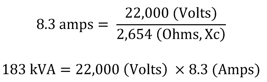
The reason large transformers are necessary when referring to cable testing has to do with the capacitance of the load being tested. Capacitive reactance (Xc) changes as a function of frequency as seen in this formula:

Therefore, if we are testing a 15 kV rated cable of approximately 10,000 feet, the capacitance would be around 1 uF. Based on the formula, the capacitive reactance at 60 Hz would be 2,654 ohms:

To apply the IEEE-recommended 22-kV test voltage would require a power supply rated for 8.3 amps, or 183 kVA:
The physical size and weight of a transformer capable of this rating is obviously not practical as a portable field unit.
The size of the necessary equipment can be substantially reduced by using the principle of resonance. If the effective capacitance of the cable is resonated with an inductor, the multiplying effect of the resonant circuit (its Q factor, presently between 50 and 120) will allow the use of a smaller test source. In the ideal case of a perfect resonance, the test source will only be required to supply enough energy to balance the true resistive loss in the inductor and cable system. One of two resonant circuits is normally used, either series or parallel. Even with the application of resonance, these power frequency high-voltage supplies can be quite large and heavy, requiring dedicated test vehicles to transport them to and from field job sites.
HIGH POTENTIAL TESTING PERFORMED AT VERY-LOW FREQUENCY (VLF)
Similar to power frequency test methods, if used alone, VLF testing is considered a Type 1, go-no-go test, but it can be used with auxiliary equipment for the purpose of Type 2 diagnostic testing. Auxiliary equipment can include partial discharge and/or dissipation factor (tan δ) couplers and measurement equipment.
The main advantage of testing at very-low frequency is that it significantly reduces the size, weight, and cost of the required power supply and thus offers greater attraction for field testing medium-voltage cables. If the test frequency were dropped to 0.1 Hz, the capacitive reactance, as calculated earlier, becomes 1.6 megohms. The same 22 kV would now only draw 14 mA or 0.303 kVA. Therefore, the size, weight, and portability of the power supply becomes very convenient for field use. VLF power supplies can be constructed for either a cosine-pulse (rectangular) waveform or sinusoidal waveform output.
Cosine-Pulse Waveform VLF
The cosine-pulse waveform version is constructed using a DC test set that acts as the high-voltage source. A DC to AC converter then changes the DC voltage to the VLF AC test signal. The converter consists of a high-voltage inductor (choke) and a rotating rectifier that changes the polarity of the cable system every 5 seconds. This generates a 0.1-Hz bipolar wave. A resonance circuit, consisting of a high-voltage inductor and a capacitor in parallel with the cable capacitance, assures sinusoidal polarity changes in the power frequency range. The use of a resonance circuit to change cable voltage polarity preserves the energy stored in the cable system. Only leakage losses have to be supplied to the cable system during the negative half of the cycle.
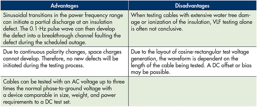
The intent of the VLF cosine-pule waveform test is to generate a 0.1-Hz bipolar pulse wave that changes polarity sinusoidally. Sinusoidal transitions in the power frequency range will then initiate a partial discharge at an insulation defect, which the 0.1-Hz pulse wave develops into a breakdown channel. During the test period, typically within minutes, a defect can be detected and forced to break through. After the defect breaks through and faults, it can then be located with standard, readily available cable fault locating equipment. Identified faults can then be repaired during the scheduled outage. When a cable system passes the VLF test, it can be returned to service. The recommended testing time periods range from 15 to 60 minutes.
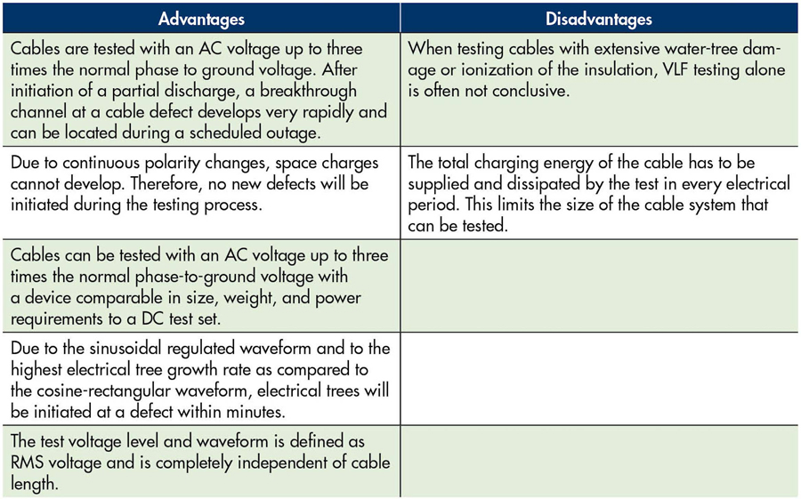
Sinusoidal Waveform VLF
The VLF test set generates sinusoidally changing waves that are less than 1 Hz (0.1 Hz, 0.05 Hz, or 0.02 Hz). When the local field strength at a cable defect exceeds the dielectric strength of the insulation, partial discharge starts. Local field strength is a function of applied test voltage, defect geometry, and space charge. After initiation of partial discharge, the partial discharge channels develop into breakthrough channels within the applied test period. When a defect is forced to break through, it can then be located with standard fault locating equipment during a scheduled outage. VLF testing guides usually recommended a test time duration of 60 minutes or less.
Test Duration and Voltage Recommendations For VLF
According to the IEEE 400.2 standard for acceptance testing cables ranging from 5 kV to 35 kV, cables that are tested between 2 Vo and 3 Vo (phase to ground), 68% of the failures occurred within 12 minutes; 89% within 30 minutes; 95% after 45 minutes; and 100% after 1 hour. These results were found using the sinusoidal and cosine-rectangular types of power supply waveforms with the most commonly used being the sinusoidal waveform.
Suggested maintenance testing is generally 15 minutes in length slightly above or below the phase to phase voltage using the sinusoidal wave. The reason for this is that the test is performed at 0.707 rms of the peak value, while testing using the cosine-rectangular waveform the test is performed at a slightly higher voltage assuming the rms is equal to the peak value.
DISSIPATION FACTOR (TAN δ) TESTING
Dissipation factor testing, also called tan δ or loss angle testing, is a diagnostic method of testing cables to determine the quality of the cable insulation. This is done to try to predict the remaining life expectancy and to prioritize cable replacement and/or injection. It is also useful for determining which other tests may be worthwhile, such as VLF withstand or partial discharge.
If the insulation of a cable is free from defects such as water trees, electrical trees, moisture, and air pockets, etc., the cable approaches the properties of a perfect capacitor (Figure 1). It is very similar to a parallel plate capacitor with the conductor and the neutral being the two plates separated by the insulation material. In a perfect capacitor, the voltage and current are phase shifted 90 degrees and the current through the insulation is capacitive.
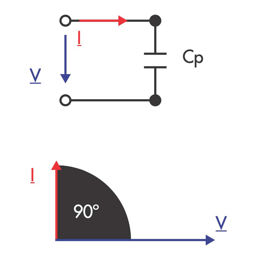
If there are impurities in the insulation, like those mentioned above, the resistance of the insulation decreases, resulting in an increase in resistive current through the insulation. It is no longer a perfect capacitor. The current and voltage will no longer be shifted 90 degrees. The shift will be something less than 90 degrees. The extent to which the phase shift is less than 90 degrees is indicative of the level of insulation contamination, hence quality/reliability. This loss angle is measured and analyzed (Figure 2).
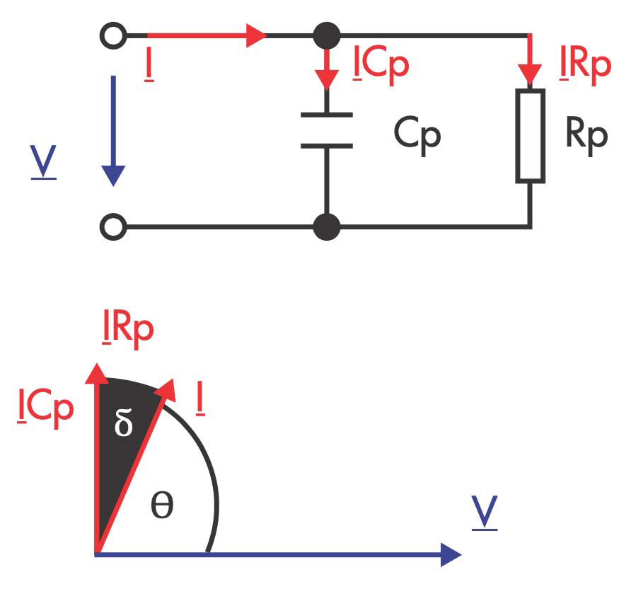
The tangent of the angle delta is measured. This will indicate the level of resistance in the insulation. By measuring IRp/ICp, we can determine the quality of the cable insulation. In perfect cable insulation, the angle would be nearly zero. An increasing angle generally indicates an increase in the resistive current through the insulation, meaning contamination. Keep in mind, however, that different insulation materials have higher or lower dielectric losses. Therefore, the angle or tan δ value may be higher for some insulating materials due to their associated dielectric losses.
We must keep in mind that the goal of tan δ testing is to provide a quality/reliability indication of an insulating system. In a cabling system, terminations and splices are part of that system. If the system insulation and all accessories are free from defects such as water trees, electrical trees, moisture, and air pockets, etc., the cabling system approaches the properties of a perfect capacitor as stated earlier. It should also be noted that if the cable circuit has transitions between multiple insulation types — for example, XLPE transitioned to EPR — the tan δ value will be influenced by the component with the higher dielectric losses. In this example, EPR has a higher dielectric loss, and the circuit would need to be evaluated based on the EPR component. This obviously hampers the effectiveness of the test since contamination growing in the XLPE may be masked by the higher dielectric losses of the EPR.
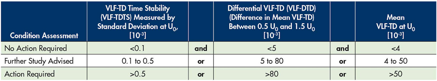
When analyzing tan δ results, we look at the stability of the tan δ reading at a given test voltage, the mean value of tan δ, and the gradient of change in the tan δ value as test voltage is increased. IEEE Std. 400.2-2013 provides historical figures of merit tables to assist in evaluating data obtained from various insulation systems.
It is important to note that tan δ does not locate defects in cabling systems; it simply gives an indication of the insulation quality between point A and B in the system. Tan δ test results may justify conducting other analysis such as time domain reflectometry (TDR) or offline partial discharge analysis and mapping to uncover possible locations of contamination and ionization.
Unfortunately, an extensive library of test values for all types of cables and accessories does not exist. Testing is typically done on a comparative basis. Keep in mind that the purpose of the test is to grade cables tested on a scale from high quality to low quality. The point of the testing is to help an asset owner prioritize cable replacement or injection. Comparative testing will show which cables are worse than others.
While it is beneficial to have previous tests to compare to for trending purposes, it is not absolutely necessary. The very first test on a cable will render valuable information. If the cable’s insulation is in good condition, the tan δ will change little as the applied voltage is increased. The capacitance and loss will be similar with 0.5 Vo or 1.5 Vo applied to the cable. If contamination is changing the capacitive/resistive nature of the insulation, then the tan δ will be higher at higher test voltages.
A tan δ measurement system consists of a high-voltage divider and measurement circuit. The high-voltage divider measures the voltage and current input to the cable and sends this information to the controller, where the voltage and current waveforms are analyzed and the tan δ number is calculated.
A voltage supply is required to energize the cable under test to the desired test voltage(s). Although power frequency can and is used in factory testing, VLF is typically the chosen power supply for field application. As mentioned earlier, to test a cable with 60 Hz power requires a very high power supply. When testing in the field, it is not practical — or in many locations not possible — to test a cable of several thousand feet with a 60 Hz supply. A typical VLF frequency of 0.1 Hz takes 600 times less power to test the same cable compared to 60 Hz, providing a significant size, weight, and cost advantage in field testing.
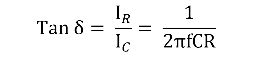
Additionally, the magnitude of the tan delta numbers increases as the frequency decreases, making measurement easier. As the following equation shows, the lower the frequency (f), the higher the tan δ number.
SUMMARY
In Part 2 of this series, we explored high potential testing techniques including Type 1 tests such as DC high potential, power frequency high potential, and VLF high potential. We also reviewed Type 2 diagnostic tests such as tan δ. In Part 3 of this series, we will focus on on-line and off-line partial discharge testing.

Thomas Sandri is Director of Technical Services at Protec Equipment Resources, where his responsibilities include the design and development of learning courses. He has been active in the field of electrical power and telecommunications for over 35 years. During his career, Tom has developed numerous training aids and training courses, has been published in various industry guides, and has conducted seminars domestically and internationally. Thomas supports a wide range of electrical and telecommunication maintenance application disciplines. He has been directly involved with and supported test and measurement applications for over 25 years and is considered an authority in application disciplines including insulation system analysis, medium- and high-voltage cable, and partial discharge analysis, as well as battery and DC systems testing and maintenance. Tom received a BSEE from Thomas Edison University in Trenton, New Jersey.